Pf700 energy savings_lab
•
0 likes•399 views

This document provides instructions for a lab demonstrating the energy savings from using a variable frequency drive (VFD) to control pump speed compared to throttling valve control. It includes an equipment list, instructions for configuring a PowerFlex 700 drive and connecting it to the pump demo, and steps for collecting power and current data at various flow rates using DriveObserver software to calculate the energy savings. Running the pump at lower speeds with the VFD reduces power consumption and wear compared to throttling the pump.
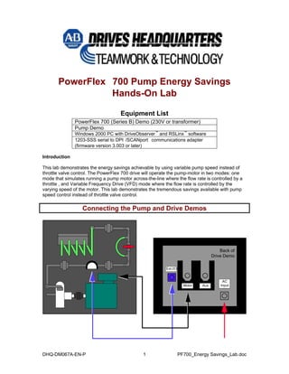
![1. Connect the flow-rate sensor, on the pump demo, to the external I/O connector on the drive demo.
2. Connect the motor, on the pump demo, to the external motor connector on the drive demo.
3. Connect the appropriate AC power to the AC Input connector on the drive demo. Make sure the plug chained to the drive demo is connected to the “Aux” socket.
Configuring the Drive
1. Pull E-STOP to power the PowerFlex 700 VC drive.
Note: To navigate to the specified parameters with the HIM (programming module), press “ALT”, choose “Param #” key, enter “parameter number” to access, then “ ”. Use the “SEL” key to move cursor to the value
2. Reset the drive to the default settings. P197 [Reset to Defaults] set to “Factory” (a value of 1).
3. Fault “F48” will occur because the parameters have been reset. Press the STOP button to clear the fault.
4. Go to the Startup menu and press the key. Select the “Basic” startup. The sections included in the Basic Startup menu are Motor Control, Motor Data/Ramp, Motor Tests, Speed Limits, Speed/Torque Control & Start/Stop I/O.
Note: press the key to move to the next selection/step of the startup procedure.
A. Motor Control section – In this section, select SVC (Sensorless vector control), without an encoder. Also choose the speed units to be in RPM. Slip compensation is automatically set.
B. Motor Data/Ramp section – enter the motor data as follows.
Power units – HP
Motor NP Power – 1.00
Motor NP FLA – 2.7
Motor NP Volts – 230
Motor NP Hertz – 60
Motor NP RPM – 3450
Motor Poles – 2
The default ramp rates for acceleration and deceleration are 10 seconds. These values may be left at default.
C. Motor Tests section – This section prompts you through a motor tuning procedure.
Select the Local HIM as the source of Start/Jog. The direction test checks for proper motor direction of rotation. (The motor should turn CCW when looking into the pump end for a forward direction of rotation.
Autotune: 50% torque is sufficient for running the auto-tune. Run the “Static Tune” because the motor is connected to the load. (It may be required to run this test more than once.)
DHQ-DM067A-EN-P 2 PF700_Energy Savings_Lab.doc](data:image/gif;base64,R0lGODlhAQABAIAAAAAAAP///yH5BAEAAAAALAAAAAABAAEAAAIBRAA7)
Recommended
More Related Content
What's hot
What's hot (16)
Viewers also liked
Similar to Pf700 energy savings_lab
Similar to Pf700 energy savings_lab (20)
More from confidencial
More from confidencial (20)
Recently uploaded
Recently uploaded (20)
Pf700 energy savings_lab
- 1. PowerFlex 700 Pump Energy Savings Hands-On Lab Equipment List PowerFlex 700 (Series B) Demo (230V or transformer) Pump Demo Windows 2000 PC with DriveObserver™ and RSLinx™ software 1203-SSS serial to DPI /SCANport communications adapter (firmware version 3.003 or later) Introduction This lab demonstrates the energy savings achievable by using variable pump speed instead of throttle valve control. The PowerFlex 700 drive will operate the pump-motor in two modes: one mode that simulates running a pump motor across-the-line where the flow rate is controlled by a throttle , and Variable Frequency Drive (VFD) mode where the flow rate is controlled by the varying speed of the motor. This lab demonstrates the tremendous savings available with pump speed control instead of throttle valve control. Connecting the Pump and Drive Demos Back ofDrive DemoACInputExt.I/OMotorAux DHQ-DM067A-EN-P 1 PF700_Energy Savings_Lab.doc
- 2. 1. Connect the flow-rate sensor, on the pump demo, to the external I/O connector on the drive demo. 2. Connect the motor, on the pump demo, to the external motor connector on the drive demo. 3. Connect the appropriate AC power to the AC Input connector on the drive demo. Make sure the plug chained to the drive demo is connected to the “Aux” socket. Configuring the Drive 1. Pull E-STOP to power the PowerFlex 700 VC drive. Note: To navigate to the specified parameters with the HIM (programming module), press “ALT”, choose “Param #” key, enter “parameter number” to access, then “ ”. Use the “SEL” key to move cursor to the value 2. Reset the drive to the default settings. P197 [Reset to Defaults] set to “Factory” (a value of 1). 3. Fault “F48” will occur because the parameters have been reset. Press the STOP button to clear the fault. 4. Go to the Startup menu and press the key. Select the “Basic” startup. The sections included in the Basic Startup menu are Motor Control, Motor Data/Ramp, Motor Tests, Speed Limits, Speed/Torque Control & Start/Stop I/O. Note: press the key to move to the next selection/step of the startup procedure. A. Motor Control section – In this section, select SVC (Sensorless vector control), without an encoder. Also choose the speed units to be in RPM. Slip compensation is automatically set. B. Motor Data/Ramp section – enter the motor data as follows. Power units – HP Motor NP Power – 1.00 Motor NP FLA – 2.7 Motor NP Volts – 230 Motor NP Hertz – 60 Motor NP RPM – 3450 Motor Poles – 2 The default ramp rates for acceleration and deceleration are 10 seconds. These values may be left at default. C. Motor Tests section – This section prompts you through a motor tuning procedure. Select the Local HIM as the source of Start/Jog. The direction test checks for proper motor direction of rotation. (The motor should turn CCW when looking into the pump end for a forward direction of rotation. Autotune: 50% torque is sufficient for running the auto-tune. Run the “Static Tune” because the motor is connected to the load. (It may be required to run this test more than once.) DHQ-DM067A-EN-P 2 PF700_Energy Savings_Lab.doc
- 3. Do not run the inertia test, as it is not needed for this lab. D. Speed Limits section – Values for the speed limits are 0 –3450RPM in the forward direction. Check/change the following: Parameter 82 [Maximum RPM] to a value of 3450 Parameter 81 [Minimum RPM] to a value of 0 E. Speed/Torque Control section – Enter this section and program the drive to use the DPI port 1 HIM as the reference signal. This allows speed control from the Up/Down arrows on the HIM. . F. Start/Stop I/O section – Enter this section to program the digital inputs to control Start, Stop, and Direction. Reverse is NOT required. Select 3-wire control. G. Done/Exit – when the above steps are completed, exit startup by selecting this section, and press the enter key. H. Configure the digital inputs and speed parameters as follows: Set this parameter… … to this value P361 [Digital In1 Sel] Not used (0) P362 [Digital In2 Sel] Not used (0) P363 [Digital In3 Sel] Jog 1 (10) P364 [Digital In4 Sel] Acc2 & Dec2 (20) P365 [Digital In5 Sel] Speed Sel 2 (16) P366 [Digital In6 Sel] Enable (1) P102 [Preset Speed 2] 3450 P141 [Accel Time 2] 0.1 I. Set P320 [Anlg In Config] / bit 0 to a 1. This configures Analog Input 1 as a current input. J. To link P476 [Scale1 In Value] to P16 [Analog In1 Value]: Back up to the Parameter level and select Parameter/ Utility/ Scaled Blocks/ Scale1 In Value. Highlight the value [0] push Alt then View. Push the down key and select link, and change to [016]. K. To configure the Scale Block so the 4-20 mA signal produces a 0-100% value at the scale block output P481 [Scale1Out Value]: Set this parameter… … to this value P478 [Scale In Lo] 4 P477 [Scale In HI] 20 P479 [Scale1Out Hi] 100 L. To link P481 [Scale1Out Value] to the HIM display and display the value in GPM: Go to the Main menu and select Preferences/User Display Lines/Dspy Ln#2/ and change to a value of 481. Select the scale and leave at a value of 1. Enter and a text string is displayed. Use the Up/Down key to scroll to a Capital “G”. Push the Sel key and scroll to “P”, Push Sel key and scroll to “M” repeat to enter spaces over unused letters. DHQ-DM067A-EN-P 3 PF700_Energy Savings_Lab.doc
- 4. 5. After completing the above procedure, verify that the drive operates per the setup. Start the drive with the HIM and use the HIM to control the speed. Observing Across-Line (Water Hammer) vs. VFD Starting Now we are ready to simulate an Across-The-Line start. 1. Be sure that Input selector switches 4, 5, and 6 are all on (turned to the right). SW 4 selects a 0.1-second Accel time, SW 5 selects the preset speed of 3450RPM, and SW 6 Enables the drive to run. 2. Push the green start button on the HIM, and observe the reaction on the tubes on the pump discharge. Starting reaction________________________________________. 3. Turn Input 6 (Enable) off and notice the tube reaction to removing drive power. Stopping reaction_______________________________________. Now we are ready to run in VFD mode. 4. Turn Input 4 (acc/Dec2) off, Input 5 (Preset2) off, and Input 6 (Enable) on. 5. Push the green start button on the HIM increase the speed of the motor to top speed, and observe the reaction on the tubes on the pump discharge. 6. Push the red stop button on the HIM. Configuring an RSLinx Serial Driver 1. Double-click on RSLinx icon on your desktop (or in the Windows Start menu select Programs > Rockwell Software > RSLinx > RSLinx) to start RSLinx. We need to start RSLinx the first time so that we can configure a serial driver. 2. In the menus, select Communications > Configure Drivers. The Configure Drivers dialog box will open. 3. Look in the list of Configured Drivers. If you see a driver whose name begins with “AB_DF1”, select it and click Delete. 4. In the Available Drivers selection box, select “RS-232 DF1” and click Add New. 5. When prompted for a name, click OK. The Configure RS-232 DF1 Devices dialog box will open. Make sure that: •The “Comm Port” is set to the communications port on your PC (COM1 for this lab) •The “Device” is set to 1770-KF2/1785-KE/SCANport 6. The baud rate is set to the baud rate of your adapter (38400 for this lab). 7. Click OK to close the dialog box. 8. Verify that the driver that you just configured is listed in the Configured Drivers list with a status of “Running”. DHQ-DM067A-EN-P 4 PF700_Energy Savings_Lab.doc
- 5. ! TIP: If the Status is “Conflict”, other software may be using the serial comm port or you may have two RSLinx serial drivers programmed for the same serial port: ! Delete duplicate drivers ! If another serial software package, such as DriveExplorer, is running, close it. Then stop and re-start the RSLinx serial driver. 9. Click Close to close the Configure Drivers dialog. 10. In the menus, select Communications > RSWho…. The RSWho dialog will open. 11. You should see both a computer (Workstation) and the connected drive device (AB_DF1-1, Data Highway Plus). ** NOTE: At this time, the drive device will be depicted by a question mark icon labeled “Unrecognized Device”. The serial driver will work. **. If this is not the case, verify that you have properly connected the PC to the drive using the 1203-SSS adapter and that power to the drive is on. If you check all these things and the connected drive device still does not appear, verify your device driver settings and try other baud rates (9600, 19200 38400) and computer comm ports (COM1, COM2). 12. Close RSLinx. Starting DriveObserver To perform this portion of the lab, you will be used DriveObserver software. 1. Double-click the DriveObserver icon on the Windows desktop (or in the Windows Start menu select Programs > DriveTools > DriveObserver) to start the software. 2. In the menus, select File > New. The sampling dialogue will open. 3. Select a sampling period of 500 milliseconds, and then click OK. Adding Traces 1. If a file is not already open, select File > New. 2. If the Add Trace dialog is not already open, select Chart >Add traces… 3. DriveObserver will display the node that is currently using by DriveExecutive. (Otherwise, you will need to use the Add Node button to select a drive.) DriveObserver may have to create the database for the drive and peripherals at the node. 4. From the drive Linear List, select the following parameters from the linear list of the node by clicking the checkbox in front of each desired parameter: P3 [Output Current]. P4 [Torque Current], P7 [Output Power], P25 [Speed Feedback], P102 [Preset Speed 2] and P481 [Scale1Out Value]. 5. Click OK. DHQ-DM067A-EN-P 5 PF700_Energy Savings_Lab.doc
- 6. Recording Data 1. In the DriveObserver toolbar, click the Record button . DriveObserver now displays new data. 2. Start the drive by pressing the ‘Start’ button on the HIM. 3. If you want to stop recording data, click the Stop button . ! TIP: Double clicking the parameter in the table beneath the chart will open a dialog so that you can change the color, minimum& maximum values, line format, etc. Energy Savings 1. Run the pump in Across-the-Line Mode and use the throttle to control the flow rate. Record the power and current readings at 100 GPM, 90 GPM, 60 GPM and 50 GPM. A. Be sure that Input selector switches 4, 5, and 6 are all on (turned to the right). Also, be sure that the throttle is open. B. Push the green start button on the HIM, and record the value of P7 [Output Power] and P3 [Output Current] when the flow rate stabilizes at 100 GPM. C. Partially close the throttle, until the flow rate stabilizes at 90 GPM. Record the value of P7 [Output Power] and P3 [Output Current]. D. Partially close the throttle, until the flow rate stabilizes at 60 GPM. Record the value of P7 [Output Power] and P3 [Output Current]. E. Fully close the throttle. Observe the flow rate stabilizes around 50 GPM. Record the value of P7 [Output Power] and P3 [Output Current]. 2. Run the pump in VFD Mode and use the motor speed to control the flow rate. Record the power and current readings at 100 GPM, 90 GPM, 60 GPM and 50 GPM. A. Be sure that Input selector switches 4 and 5 are off on (turned to the left), and 6 is on (turned to the right). Also, be sure that the throttle is fully open. B. Push the green start button on the HIM, and increase the motor speed until the flow rate stabilizes at 100 GPM (at about 3450 RPM). Record the value of P7 [Output Power] and P3 [Output Current]. C. Reduce the motor speed, until the flow rate stabilizes at 90 GPM (at about 2900 RPM). Record the value of P7 [Output Power] and P3 [Output Current]. D. Reduce the motor speed, until the flow rate stabilizes at 60 GPM (at about 2080 RPM). Record the value of P7 [Output Power] and P3 [Output Current]. E. Reduce the motor speed, until the flow rate stabilizes at 50 GPM (at about 1900 RPM). Record the value of P7 [Output Power] and P3 [Output Current]. DHQ-DM067A-EN-P 6 PF700_Energy Savings_Lab.doc
- 7. DHQ-DM067A-EN-P 7 PF700_Energy Savings_Lab.doc Across-the-Line Mode VFD Mode Flow Rate (GPM) P7 [Output Power] P3 [Output Current] P7 [Output Power] P3 [Output Current] 100 90 60 50 Open the Microsoft Excel spreadsheet. Put a value of one in cell C3 and compare your recorded values to the values in the spreadsheet. Next, vary the value in cell C3 and observe the calculated energy savings for different size pumps. Note that typical flow requirements for pump applications are between 60% and 90% of the pump rating. Other Benefits Listen to the cavitation (the creation of cavities in the fluid going through the pump) that occurs when the pump is throttled back to lower rates. At reduced rates the system pressure increases, and fluid can actually boil at the tip of the pump impeller. Notice the heating that occurs after short periods of running at throttled conditions. Several maintenance considerations now become apparent: Pump bearing and seal life can be improved when pump speed is controlled to meet flow requirements. When pumping materials with any particulate, impeller wear can be greatly reduced when pump speed is controlled to meet flow requirements.