SlideShare a Scribd company logo
1 of 14
6. Control Functions and Parameter Settings
6-6-4 Explanation of Block-C parameter functions
C00-0 Run command method
Set the run command method for the remote operation mode (when "LCL" LED on operation
panel is OFF). Set the sequence command, F.RUN, R.RUN and HOLD with C03-0, C03-2
and C03-5.
= 1: F·RUN, R·RUN
PSI1 to PSI11
F・RUN
RY0
R・RUN
Frequency
Speed
Reverse run
Forward run
= 2: RUN, REV
PSI1 to PSI11
F・RUN(RUN)
RY0
R・RUN(REV)
Frequency
Speed
Reverse run
Forward run
= 3: Self hold
PSI1 to PSI11
F・RUN
RY0
R・RUN
Stop
HOLD
Frequency
Speed
Reverse run
Forward run
(Note) PSI8 to 11 can be used only when the relay interface option is mounted.
6 – 135
PSI1 to PSI11
RY0
6. Control Functions and Parameter Settings
C00-1 Run/stop methods
C00-2 Jog stop method
= 1: Coast to stop
= 2: Deceleration stop
Coast to stop refers to stopping by turning the output OFF simultaneously with the stop
command (F·RUN and R·RUN OFF).
Deceleration stop refers to stopping by decelerating to the stopping frequency with the ramp
down after the stop command, and then applying the DC-brake to stop.
Output frequency
Motor speed
Output frequency
during coast to
stop DC brake
Ramp down to stop
Motor speed during
coast to stop
RUN
(Note) When not using the pick-up function to restart after coast to stop, confirm that the
motor is stopped. When not using the pickup function, if the inverter is started while
the motor is rotating, the inverter may trip.
C00-3 Emergency stop (EMS) input logic
Set the input logic of the emergency stop sequence input signal EMS.
= 1: Close to stop (when a contact is connected)
= 2: Open to stop (when b contact is connected)
Select the EMS signal input terminal from the
control PCB terminal block PSI to 11, and set
with C03-1.
(Note) PSI8 to 11 can be used only when the
relay interface option is mounted.
C00-4 Emergency stop (EMS) mode
Set the method of stopping when the emergency stop sequence input EMS turns ON.
= 1: Coast to stop, without fault output
= 2: Coast to stop, with fault output (When the EMS signal turns ON, the output will be shut
off, and FLT will be output.)
= 3: Ramp down to stop (without fault output)
6 – 136
6. Control Functions and Parameter Settings
C00-5 Control source switchover method (J1 setting)
J1 setting =1: OFF =2: ON
Select whether to use the sequence input signals from the control PCB terminal block in the
local operation mode (when "LCL" LED on operation panel is ON).
Refer to section 5-5 for details.
C00-6 Control source switchover method (J2 setting)
J2 setting =1: OFF =2: ON
Select the auxiliary command input when the COP command is ON.
Refer to section 5-5 for details.
C00-7 Run contact output condition selection
The conditions for turning the sequence RUN output ON are set.
= 1: ON at pre-excitation (EXC)
= 2: OFF at pre-excitation (EXC)
C02-0~8 Various setting input selection
Refer to section 5-9 for details.
C03-0~F Sequence input terminal function − 1
C04-0~F Sequence input terminal function − 2
C05-0~7 Sequence input terminal function − 3
C06-0~A Sequence input terminal function − 4
Refer to section 5-3, 5-6 for details. Refer to the explanation for B06-0 to 6 (ratio interlock
bias increase/decrease function) for details on C03-A and C04-9 to A.
C07-0~A Analog input terminal function
Refer to section 5-7 for details.
6 – 137
6. Control Functions and Parameter Settings
C08-0 Auto start (To F・RUN/R・RUN)
= 1: OFF (runs with the run command ON after pre-charging)
= 2: ON without pick-up
If the run command is ON when the power is turned on, run will start after the inverter
is charged.
(Note 1) Pick-up is not executed with this setting, so if the motor is rotating when the power
is turned ON, the inverter operation could trip.
ON
Output frequency
Motor speed
Pre-charging
Power supply
RUN
= 3: ON with pick-up
If the run command turns ON when the power turns ON, pick-up will start when the
inverter charging is completed, and then operation will start.
Set this when using momentary restart.
(Note 2) The speed can be detected with the IM vector control with sensor and PM motor
control (C30-0 f0 = 3, 4). As pickup operation is not carried out, set C08-0 to 2.
Output frequency
Motor speed
Pre-charging
(internal RDY)
Motor speed search
(For V/f control, IM speed sensor-less vector control C30-0 f0 =1,2)
Power supply
Motor speed
RUN
(Note 3) If auto start (C08-0 = 2, 3) is used, undervoltage fault will not be detected.
6 – 138
6. Control Functions and Parameter Settings
C09-0 Parameter protection
Set this parameter to prevent unintentional operations from operation panel.
Changing of the data can be protected per function group with the setting value as shown
below.
(Note 1) Set 2 to prohibit all changes.
(Note 2) Set 1 to allow all changes. The 9 setting is for maker maintenance, so do not set it.
(Note 3) When using the password number function (when C28-0 is set to 2), this
parameter will also be locked. Set U00-1 to the value set with C28-1 to unlock the
protection.
C09-1 Operation panel lock
This setting protects the operation panel FWD, REV and STOP key operations.
= 1: All operation possible
= 2: All operation prohibited (Note, the motor will stop when the STOP key is pressed for
two seconds)
= 3: Only STOP key can be operated.
C09-2 LCL switchover protection
= 1: LCL mode switchover ( LCL
SET
+ STOP
keys) during running disabled
= 2: LCL mode switchover ( LCL
SET
+ STOP
keys) during running enabled
(Note) When switching from the local mode to the remote mode, if the terminal block RUN,
R.RUN, F.JOG or R.JOG is ON, the mode will not switch even if operation is
stopped.
C09-3 Reveres run sequence (R·RUN) prohibit
C09-4 Reverse run jogging sequence (R·JOG) prohibit
= 1: Enable = 2: Prohibit
Set this to prevent unintentional reverse run operation.
When set to "2", the sequence input "R RUN(R JOG)" operation command will be disabled.
Note that if the reverse run setting (negative value) is input into the speed setting during
"F·RUN(F JOG)" operation, reverse run will start.
6 – 139
value
Block
A
Block B, C
Basic Extn. S/W H/W
1     
2 × × × × ×
3  × × × ×
4  ×  × ×
5  ×   ×
6     
7 ~ 8 × × × × ×
9     
 : Unprotected
(changeable)
× : Protected
(unchangeable)
6. Control Functions and Parameter Settings
C09-5 Reverse run during ACR mode prohibit
= 1: Enable = 2: Prohibit
Set this to prevent unintentional reverse run operation.
When set to “2”, reverse run during ACR operation will be prohibited.
The reverse run speed will be limited to approx. 1% if reverse run is started.
This setting is ignored in the V/f mode.
C09-6 Fault history buffer clear
The fault history details can be cleared by setting the value to 1 and then pressing LCL
SET
key.
This setting will not be registered in the internal memory. Thus, this parameter must be set
each time.
Nothing will occur if set to a value other than 1.
Use this before handing the unit over to the final user.
(Note) The setting values exceeding 2000 are codes for maker maintenance, so do not set.
C09-7 Default value load
All values per function group are changed to the default values.
9: All default values load (Excluding the maker maintenance parameters)
10: Parameter A
11: Parameters B, C basic functions
12: Parameters B, C extended functions
13: Parameter B software option function
Parameter C hardware option function
14: Parameters B basic functions
15: Parameters B extended functions
16: Parameter B software option function
17: Parameters C basic functions
18: Parameters C extended functions
19: Parameter C hardware option function
Nothing will occur when values other than the above are set.
This parameter setting value will not be registered in the internal memory.
(Note) The setting values exceeding 2000 are codes for maker maintenance, so do not
set. If set, the following inverter operation may be abnormal.
C10-0~7 Custom parameter register
Refer to section 4-4 for details on operating these parameters.
6 – 140
6. Control Functions and Parameter Settings
C11-0 Default mode setting
Set which operation mode the operation panel starts up when the power is turned ON.
=1: Local operation mode (LCL) =2: Remote operation mode (RMT)
C11-1 Operation command at auto start setting
=1: Stop =2: Forward run =3: Reverse run
Set the default operation mode at power ON when using the auto start function (C08-0=2, 3)
in the local operation mode (operating with the operation panel).
For example, if C11-1 is set to 2 and operation is enabled after power ON (sequences
RDY1, RDY2, MC are all ON), the forward run will take place.
C11-2 Operation panel frequency change operation
Set whether to change the frequency and speed setting values in real time.
=1: Change setting value in real time =2: Change setting value when set key is pressed
C11-3 Display parameter at power ON selection
Select the parameters displayed on the operation panel at power ON.
Refer to the following diagram.
0. 00. 0
Sub No.
Main No.
0 : D block
1 : A block
C11-4 LCD panel: Language setting
Select the language displayed on the LCD panel.
=0: English
=1: French
=2: German
=3: Spanish
=4: Italian
(Note) This is displayed only when the LCD panel is connected.
C11-5 LCD panel: Contrast adjustment
Adjust the contrast of the characters displayed on the LCD panel.
The character color will darken as a larger value is set.
(Note) This is displayed only when the LCD panel is connected.
6 – 141
6. Control Functions and Parameter Settings
C11-6 LCD panel: Backlight OFF timer setting
Set the time that the LCD panel backlight is ON.
Set the ON time with a second unit.
If the setting value is "0", the backlight will be ON at all times.
(Note) This is displayed only when the LCD panel is connected.
C11-7 Operation panel operation mode selection
The operation panel parameter operation method can be selected from two methods.
Refer to section 4-1-3 Selecting the operation method.
C12-0 AI1 terminal input mode selection
C12-4 AI2 terminal input mode selection
Select the input mode for the AI1 and AI2 terminals.
C12-0, 4 = 1 : Voltage input
= 2 : Current input
Refer to section 5-7 for details on using the analog input terminal.
C12-1 AI1 voltage input mode selection
C12-5 AI2 voltage input mode selection
When the AI1 and AI2 terminal input mode is set to voltage input (C12-0, 4 = 1), set the full
scale of these terminal input signals.
C12-1, 5 = 1 : 0 to 10V
= 2 : 0 to 5V
= 3 : 1 to 5V
As an example, the relation of the voltage input value and speed setting value when the AI1
and AI2 terminal input function is used for the speed setting is shown below. Refer to Table
5-7-1 for the relation of the analog input value and each setting value when using the input
terminal for a function other than speed setting.
Setting frequency/Setting speed
Max. frequency
Max. speed
0 1V
C12-1,5=3
C12-1,5=1,2
5V :C12-1=1
10V:C12-2=2
Voltage input mode
Input voltage
6 – 142
6. Control Functions and Parameter Settings
C12-2 AI1 current input mode selection
C12-6 AI2 current input mode selection
When the AI1 and AI2 terminal input mode is set to current input (C12-0, 4 = 2), set the full
scale of these terminal input signals.
C12-2, 6 = 1 : 4 to 20mA
= 2 : 0 to 20mA
As an example, the relation of the current input value and speed setting value when the AI1
and AI2 terminal input function is used for the speed setting is shown below. Refer to Table
5-7-1 for the relation of the analog input value and each setting value when using the input
terminal for a function other than speed setting.
0 4mA
C12-2,6=1
C12-2,6=2
20mA
Setting frequency/Setting speed
Max. frequency
Max. speed
Current input mode
Input voltage
6 – 143
6. Control Functions and Parameter Settings
C12-8 AI3 terminal input mode selection
C12-9 AI3 input gain
Set the full scale of the AI3 terminal analog input signal with C12-8.
C12-8 = 1 : -10V to +10V
= 2 : -5V to +5V
= 3 : +1V to +5V
A multiplication gain can be applied on the AI3 terminal input value with C12-9.
As an example, the relation of the voltage input value and speed setting value when the AI3
terminal input function is used for the speed setting is shown below. Refer to Table 5-7-1 for
the relation of the analog input value and each setting value when using the input terminal
for a function other than speed setting.
Refer to section 5-7 for details on using the analog input terminals.
Setting frequency/Setting speed
(Forward run)
Max. frequency
Max. speed
Max. frequency
Max. speed
-10V : C12-8=1
-5V : C12-8=2
1V
C12-8=1,2
C12-8=3
+10V : C12-8=1
+5V : C12-8=2
When running with
sequence command
R•RUN
When running with
sequence
command F•RUN
(Reverse run)
C12-3 Filter time constant for AI1 input
C12-7 Filter time constant for AI2 input
C12-A Filter time constant for AI3 input
The filter time constant for the input value of the AI1, AI2 and AI3 terminals can be set.
Fluctuation of the setting value caused by input signal noise or chattering, etc., can be
suppressed by increasing the time constant.
C12-B Program setting filter
The program speed and ramp setting are set with the sequence commands S0 to SE, but
chattering could occur when these input terminals are changed. In order to avoid this, batch
filter processing is performed for S0 to SE.
The input signal is validated when the S0 to SE input terminals obtain the same value for
longer than the set time, so the program settings will not change for the time set in C12-B
after the input is changed.
Set C12-B to a time longer than that at which chattering could occur, and lower than the
setting delay tolerance time.
6 – 144
6. Control Functions and Parameter Settings
C12-C Pulse train input : 0% setting frequency (F1)
C12-D Pulse train input : 100% setting frequency (F2)
C12-E Pulse train input frequency LPF time constant
C12-F Pulse train input judgment time
Refer to section 5-7-3 for details related to the pulse train input function.
C13-0 A01 terminal output
C13-1 A02 terminal output
The inverter's internal parameters can be output from the control PCB analog output
terminals A01 and A02.
C13-7~A Built-in PLC input selection 1~4
The inverter output analog signals can be input to the built-in PLC. Select the details set in
memory numbers 10h to 13h.
The parameters corresponding to the C13-0,1,7 to A setting values and the full scale of
those output signals is shown below. The output voltage and current values are output as a
percentage of the full scale. Refer to section 5-8 for details on using the analog output
terminals. Refer to section 6-11 for details on using Built-in PLC.
The parameters corresponding to the C13-0, 1 setting values and the full scale of those
output signals is shown below. The output voltage and current values are output as a
percentage of the full scale. Refer to section 5-8 for details on using the analog output
terminals.
(Note 1) DM1 and DM2 for maker maintenance are to be used only by the maker for maintenance.
The user must not set C13-0, 1 to 20 or 21.
C13-2 RA-RC output parameters
C13-3~5 PSO1, 2, 3 output parameters
C13-6 FA-FC output parameters
Refer to section 5-6-2 for details.
6 – 145
ValueParameterFull scale11Torque currentMotor rated current ×
212Excitation currentMotor rated current × 213Actual motor rotation
speedMax. speed14Namp outputRated torque × 215OLT monitor
(motor protection)100%16Built-in PLC output 11000h17Built-in
PLC output 21000h18Built-in PLC output 31000h19Built-in PLC
output 41000h20DM1 for maker maintenance1000h21DM2 for
maker maintenance1000h
ValueParameterFull scale0Output frequencyMax.
frequency1Setting frequency
Setting speedMax. frequency
Max. speed2Ramp outputMax. frequency
Max. speed3Output current (Motor)Motor rated current ×
24Output current (Drive)Drive rated current × 25Output
voltageMotor rated voltage6Motor output power(Motor rated
voltage × Motor rated current) × 27DC voltage200V Series :
300V
400V Series : 600V8OLT monitor
(unit protection)100%9Heat sink temperature100°C10Motor
speedMax. speed
6. Control Functions and Parameter Settings
C13-B Pulse train output function
C13-C Pulse frequency at 0%
C13-D Pulse frequency at maximum frequency/speed
C13-E Pulse train output parameter selection
C13-F Output parameter absolute value calculation selection
Refer to section 5-8-3 for details on the pulse train output function.
C14-7, 8 A01, A02 output method selection
C14-0, 1 A01, A02 output gain
C14-3, 4 A01, A02 output offset (Voltage)
C14-5, 6 A01, A02 output offset (Current)
The block diagram for the control PCB analog outputs A01 and A02 is shown below.
Internal parameter
(Set C13-0)
C14-0
(Note 1)
C14-3 (Voltage output)
C14-5 (Current output)
(Note 1)
+
+
AO1
COM
Internal parameter
(Set C13-1)
C14-1
(Note 1)
C14-4 (Voltage output)
C14-6 (Current output)
(Note 1)
+
+
AO2
COM
Gain Offset
6 – 146
6. Control Functions and Parameter Settings
(Note 1) The maximum output voltage for the A01 and A02 output is approx. 11V. Thus,
even if the gain or offset are set to a large value, a voltage higher than this
maximum level will not be output.
Set the A01, A02 output method with C14-7, 8.
C14-7, 8 = 1: Voltage output 0V to 10V
= 2: Voltage output 0V to 10V (with 5V offset)
= 3: Current output 4mA to 20mA
When using A01, A02 for the voltage output (C14-7, 8 = 1 or 2), connect the control PCB
A01/A02 L bit (W3, W4) to the voltage mode side. When using for the current output (C14-
7, 8 = 3), set the L bit to the current mode side. Refer to section 5-8 for details on this.
When C14-7, 8 is set to 2, the parameter reference point is automatically set to 5V, and the
output value gain is set to 0.5-fold.
A gain can be applied on the internal parameter value set with C13-0, 1.
Set this gain with C14-0, 1.
When C14-7, 8 is set to 2 and the output gain is set with C14-0, 1, the gain will be (0.5 ×
C14-0, 1).
Of the parameters selected with C13-0, 1, those shown below are coded with a plus/minus
sign. When these parameters are selected, plus or minus can be added by offsetting the
output value.
Set C14-3, 4 for the voltage output, and C14-5, 6 for the current output.
Setting
value
Parameter Full scale
0 Output frequency Max. frequency
1
Setting frequency
Setting speed
Max. frequency
Max. speed
10 Motor speed Max. speed
11 Torque current Motor rated current × 2
12 Excitation current Motor rated current × 2
13 Actual motor rotation speed Max. speed
14 Namp output Rated torque × 2
An example of setting a 5V offset for the voltage output is shown below.
If C14-7, 8 is set to 2, the offset amount when the offset is set with C14-3, 4 becomes (5V +
C14-3, 4 setting value).
0V
10V
5V
-100% 100%
For offset 5V, gain 0.50
Meter output [V]
Internal parameter
value [%]0V
10V
100%-100%
When offset is not set
(Offset = 0V, gain = 1.00)
Meter output [V]
When offset is set
Internal
parameter
value [%]
(Note 2) If plus or minus is set with offset, the signal is not output from A01, A02 when the
power is shut off, so the output will be 0V (-100% in above example).
6 – 147
6. Control Functions and Parameter Settings
C14-2 Random scale display coefficient
Set the display value coefficient for the monitor parameter D00-4 (output frequency, speed
random scale display) and D01-4 (set frequency, speed, ramp input random scale display.
The result of multiplying the output frequency or set frequency, etc., with this setting value is
displayed at D00-4, D01-4).
C14-9~B AI1, AI2, AI3 random scale coefficient
Set the random scale coefficient of the value displayed at monitor parameter D08-0 to 2
(analog input AI1, AI2, AI3 random scale display).
6 – 148

More Related Content

What's hot

JVL AC Servo Motor Controllers AMC20, AMC21 and AMC22
JVL AC Servo Motor Controllers AMC20, AMC21 and AMC22JVL AC Servo Motor Controllers AMC20, AMC21 and AMC22
JVL AC Servo Motor Controllers AMC20, AMC21 and AMC22
Electromate
 

What's hot (16)

Process control lab manual
Process control lab manualProcess control lab manual
Process control lab manual
 
Instrumentation & control of typical material handling of FGD Plant
Instrumentation & control of typical material handling of FGD PlantInstrumentation & control of typical material handling of FGD Plant
Instrumentation & control of typical material handling of FGD Plant
 
JVL AC Servo Controllers
JVL AC Servo ControllersJVL AC Servo Controllers
JVL AC Servo Controllers
 
2020 r1 1ok
2020 r1 1ok2020 r1 1ok
2020 r1 1ok
 
Catalog lift hpc
Catalog lift hpcCatalog lift hpc
Catalog lift hpc
 
Exj 8 p
Exj 8 pExj 8 p
Exj 8 p
 
Cataloge ge 3.control and_automation_dienhathe.com-4_19_vat300_e_c6-6-3_2_rev_c1
Cataloge ge 3.control and_automation_dienhathe.com-4_19_vat300_e_c6-6-3_2_rev_c1Cataloge ge 3.control and_automation_dienhathe.com-4_19_vat300_e_c6-6-3_2_rev_c1
Cataloge ge 3.control and_automation_dienhathe.com-4_19_vat300_e_c6-6-3_2_rev_c1
 
Catalog Frenic mini(NEW) -www.haophuong.com
Catalog Frenic mini(NEW) -www.haophuong.comCatalog Frenic mini(NEW) -www.haophuong.com
Catalog Frenic mini(NEW) -www.haophuong.com
 
Bien tan-mini
Bien tan-miniBien tan-mini
Bien tan-mini
 
JVL AC Servo Motor Controllers AMC20, AMC21 and AMC22
JVL AC Servo Motor Controllers AMC20, AMC21 and AMC22JVL AC Servo Motor Controllers AMC20, AMC21 and AMC22
JVL AC Servo Motor Controllers AMC20, AMC21 and AMC22
 
Galil legacy catalog
Galil legacy catalogGalil legacy catalog
Galil legacy catalog
 
Tlk94 Controller
Tlk94 ControllerTlk94 Controller
Tlk94 Controller
 
Pwm(Pulse Width Modulation) presentation
Pwm(Pulse Width Modulation) presentationPwm(Pulse Width Modulation) presentation
Pwm(Pulse Width Modulation) presentation
 
Iai erc3 cj0184 4-a-ust-2-0214
Iai erc3 cj0184 4-a-ust-2-0214Iai erc3 cj0184 4-a-ust-2-0214
Iai erc3 cj0184 4-a-ust-2-0214
 
Schneideratv 58 usermanual
Schneideratv 58 usermanualSchneideratv 58 usermanual
Schneideratv 58 usermanual
 
Mitsubishi inverter freqrol-e700 series dienhathe.vn
Mitsubishi inverter freqrol-e700 series dienhathe.vnMitsubishi inverter freqrol-e700 series dienhathe.vn
Mitsubishi inverter freqrol-e700 series dienhathe.vn
 

Similar to Cataloge ge 3.control and_automation_dienhathe.com-4_20_vat300_e_c6-6-4_1_rev_b

Linmot overzicht servo_controller_serie_e1100_duits_4_mb
Linmot overzicht servo_controller_serie_e1100_duits_4_mbLinmot overzicht servo_controller_serie_e1100_duits_4_mb
Linmot overzicht servo_controller_serie_e1100_duits_4_mb
mahdi nasiri
 

Similar to Cataloge ge 3.control and_automation_dienhathe.com-4_20_vat300_e_c6-6-4_1_rev_b (20)

honeywell-dc1000-dc1010-dc1030-dc1040-manual.pdf
honeywell-dc1000-dc1010-dc1030-dc1040-manual.pdfhoneywell-dc1000-dc1010-dc1030-dc1040-manual.pdf
honeywell-dc1000-dc1010-dc1030-dc1040-manual.pdf
 
10 vat300 e_c4-1_rev_b
10 vat300 e_c4-1_rev_b10 vat300 e_c4-1_rev_b
10 vat300 e_c4-1_rev_b
 
Cataloge ge 3.control and_automation_dienhathe.com-4_17_vat300_e_c6-6-2_rev_a
Cataloge ge 3.control and_automation_dienhathe.com-4_17_vat300_e_c6-6-2_rev_aCataloge ge 3.control and_automation_dienhathe.com-4_17_vat300_e_c6-6-2_rev_a
Cataloge ge 3.control and_automation_dienhathe.com-4_17_vat300_e_c6-6-2_rev_a
 
Cataloge ge 3.control and_automation-17_vat300_e_c6-6-2_rev_a
Cataloge ge 3.control and_automation-17_vat300_e_c6-6-2_rev_aCataloge ge 3.control and_automation-17_vat300_e_c6-6-2_rev_a
Cataloge ge 3.control and_automation-17_vat300_e_c6-6-2_rev_a
 
BLD-AC1000S.pdf
BLD-AC1000S.pdfBLD-AC1000S.pdf
BLD-AC1000S.pdf
 
07 vat300 e_c3-4-2_rev_b
07 vat300 e_c3-4-2_rev_b07 vat300 e_c3-4-2_rev_b
07 vat300 e_c3-4-2_rev_b
 
PLC y Electroneumática: inversor de control vectorial
PLC y Electroneumática: inversor de control vectorialPLC y Electroneumática: inversor de control vectorial
PLC y Electroneumática: inversor de control vectorial
 
Delta ia asda-a2_speed
Delta ia asda-a2_speedDelta ia asda-a2_speed
Delta ia asda-a2_speed
 
09 vat300 e_c3-4-4_rev_a
09 vat300 e_c3-4-4_rev_a09 vat300 e_c3-4-4_rev_a
09 vat300 e_c3-4-4_rev_a
 
Cnc3ds huong dan su dung bo phat xung da nang
Cnc3ds huong dan su dung bo phat xung da nangCnc3ds huong dan su dung bo phat xung da nang
Cnc3ds huong dan su dung bo phat xung da nang
 
08 vat300 e_c3-4-3_rev_a1
08 vat300 e_c3-4-3_rev_a108 vat300 e_c3-4-3_rev_a1
08 vat300 e_c3-4-3_rev_a1
 
Catalog mikro mikro mk232a-user
Catalog mikro mikro mk232a-userCatalog mikro mikro mk232a-user
Catalog mikro mikro mk232a-user
 
Catalog mikro mikro mk232a-user-dienhathe.vn
Catalog mikro mikro mk232a-user-dienhathe.vnCatalog mikro mikro mk232a-user-dienhathe.vn
Catalog mikro mikro mk232a-user-dienhathe.vn
 
Catalog mikro mikro mk232a-user
Catalog mikro mikro mk232a-userCatalog mikro mikro mk232a-user
Catalog mikro mikro mk232a-user
 
Cataloge ge 3.control and_automation-31_vat300_e_appendix3_5_rev_a
Cataloge ge 3.control and_automation-31_vat300_e_appendix3_5_rev_aCataloge ge 3.control and_automation-31_vat300_e_appendix3_5_rev_a
Cataloge ge 3.control and_automation-31_vat300_e_appendix3_5_rev_a
 
Linmot overzicht servo_controller_serie_e1100_duits_4_mb
Linmot overzicht servo_controller_serie_e1100_duits_4_mbLinmot overzicht servo_controller_serie_e1100_duits_4_mb
Linmot overzicht servo_controller_serie_e1100_duits_4_mb
 
Catalog mikro mikro mk233a-user
Catalog mikro mikro mk233a-userCatalog mikro mikro mk233a-user
Catalog mikro mikro mk233a-user
 
Catalog mikro mikro mk233a-user-dienhathe.vn
Catalog mikro mikro mk233a-user-dienhathe.vnCatalog mikro mikro mk233a-user-dienhathe.vn
Catalog mikro mikro mk233a-user-dienhathe.vn
 
Catalog mikro mikro mk233a-user
Catalog mikro mikro mk233a-userCatalog mikro mikro mk233a-user
Catalog mikro mikro mk233a-user
 
Maxvu tech support lvl presentation na
Maxvu tech support lvl presentation na Maxvu tech support lvl presentation na
Maxvu tech support lvl presentation na
 

More from Dien Ha The

More from Dien Ha The (20)

Vnd feb 2020 price list schneider (1)
Vnd feb 2020 price list schneider (1)Vnd feb 2020 price list schneider (1)
Vnd feb 2020 price list schneider (1)
 
Resize bientanfuji-dienhathe.com
Resize bientanfuji-dienhathe.comResize bientanfuji-dienhathe.com
Resize bientanfuji-dienhathe.com
 
Fed e-quick-start-up-guide-bientanfuji-dienhathe.com
Fed e-quick-start-up-guide-bientanfuji-dienhathe.comFed e-quick-start-up-guide-bientanfuji-dienhathe.com
Fed e-quick-start-up-guide-bientanfuji-dienhathe.com
 
Fed e-quick-start-manual-bientanfuji-dienhathe.com
Fed e-quick-start-manual-bientanfuji-dienhathe.comFed e-quick-start-manual-bientanfuji-dienhathe.com
Fed e-quick-start-manual-bientanfuji-dienhathe.com
 
Ls bang gia ls ap dung 20 04-2019
Ls bang gia ls ap dung 20 04-2019Ls bang gia ls ap dung 20 04-2019
Ls bang gia ls ap dung 20 04-2019
 
Mitsubishi graphic operation terminal got2000 series parts library book
Mitsubishi graphic operation terminal got2000 series parts library bookMitsubishi graphic operation terminal got2000 series parts library book
Mitsubishi graphic operation terminal got2000 series parts library book
 
Mitsubishi inverter fr-a700-instruction-manualbasic-160425031653
Mitsubishi inverter fr-a700-instruction-manualbasic-160425031653Mitsubishi inverter fr-a700-instruction-manualbasic-160425031653
Mitsubishi inverter fr-a700-instruction-manualbasic-160425031653
 
Mitsubishi graphic operation terminal got2000 series gt2103 new product release
Mitsubishi graphic operation terminal got2000 series gt2103 new product releaseMitsubishi graphic operation terminal got2000 series gt2103 new product release
Mitsubishi graphic operation terminal got2000 series gt2103 new product release
 
Mitsubishi graphic operation terminal got2000 series got mobile function quic...
Mitsubishi graphic operation terminal got2000 series got mobile function quic...Mitsubishi graphic operation terminal got2000 series got mobile function quic...
Mitsubishi graphic operation terminal got2000 series got mobile function quic...
 
Mitsubishi graphic operation terminal got2000 series drive control interactiv...
Mitsubishi graphic operation terminal got2000 series drive control interactiv...Mitsubishi graphic operation terminal got2000 series drive control interactiv...
Mitsubishi graphic operation terminal got2000 series drive control interactiv...
 
Mitsubishi inverter option catalog
Mitsubishi inverter option catalogMitsubishi inverter option catalog
Mitsubishi inverter option catalog
 
Mitsubishi low voltage ws-v series mccb and elcb
Mitsubishi low voltage ws-v series mccb and elcbMitsubishi low voltage ws-v series mccb and elcb
Mitsubishi low voltage ws-v series mccb and elcb
 
Mitsubishi graphic operation terminal got2000 series (concise)
Mitsubishi graphic operation terminal got2000 series (concise)Mitsubishi graphic operation terminal got2000 series (concise)
Mitsubishi graphic operation terminal got2000 series (concise)
 
Mitsubishi low voltage ws-v series comparison of previous and new models
Mitsubishi low voltage ws-v series comparison of previous and new modelsMitsubishi low voltage ws-v series comparison of previous and new models
Mitsubishi low voltage ws-v series comparison of previous and new models
 
Mitsubishi inverter inverter family
Mitsubishi inverter inverter familyMitsubishi inverter inverter family
Mitsubishi inverter inverter family
 
Mitsubishi low voltage miniature circuit breakers din series
Mitsubishi low voltage miniature circuit breakers din seriesMitsubishi low voltage miniature circuit breakers din series
Mitsubishi low voltage miniature circuit breakers din series
 
Mitsubishi inverter freqrol-hc2 series
Mitsubishi inverter freqrol-hc2 seriesMitsubishi inverter freqrol-hc2 series
Mitsubishi inverter freqrol-hc2 series
 
Mitsubishi low voltage mccb and elcb(ws-v series) y0720-version 1-mitsu
Mitsubishi low voltage mccb and elcb(ws-v series) y0720-version 1-mitsuMitsubishi low voltage mccb and elcb(ws-v series) y0720-version 1-mitsu
Mitsubishi low voltage mccb and elcb(ws-v series) y0720-version 1-mitsu
 
Mitsubishi inverter freqrol-f700 pj series
Mitsubishi inverter freqrol-f700 pj seriesMitsubishi inverter freqrol-f700 pj series
Mitsubishi inverter freqrol-f700 pj series
 
Mitsubishi inverter catalog-mitsubishi-inverter-option-160426021125
Mitsubishi inverter catalog-mitsubishi-inverter-option-160426021125Mitsubishi inverter catalog-mitsubishi-inverter-option-160426021125
Mitsubishi inverter catalog-mitsubishi-inverter-option-160426021125
 

Recently uploaded

Call Girls in South Ex (delhi) call me [🔝9953056974🔝] escort service 24X7
Call Girls in South Ex (delhi) call me [🔝9953056974🔝] escort service 24X7Call Girls in South Ex (delhi) call me [🔝9953056974🔝] escort service 24X7
Call Girls in South Ex (delhi) call me [🔝9953056974🔝] escort service 24X7
9953056974 Low Rate Call Girls In Saket, Delhi NCR
 
"Lesotho Leaps Forward: A Chronicle of Transformative Developments"
"Lesotho Leaps Forward: A Chronicle of Transformative Developments""Lesotho Leaps Forward: A Chronicle of Transformative Developments"
"Lesotho Leaps Forward: A Chronicle of Transformative Developments"
mphochane1998
 
Standard vs Custom Battery Packs - Decoding the Power Play
Standard vs Custom Battery Packs - Decoding the Power PlayStandard vs Custom Battery Packs - Decoding the Power Play
Standard vs Custom Battery Packs - Decoding the Power Play
Epec Engineered Technologies
 
1_Introduction + EAM Vocabulary + how to navigate in EAM.pdf
1_Introduction + EAM Vocabulary + how to navigate in EAM.pdf1_Introduction + EAM Vocabulary + how to navigate in EAM.pdf
1_Introduction + EAM Vocabulary + how to navigate in EAM.pdf
AldoGarca30
 
DeepFakes presentation : brief idea of DeepFakes
DeepFakes presentation : brief idea of DeepFakesDeepFakes presentation : brief idea of DeepFakes
DeepFakes presentation : brief idea of DeepFakes
MayuraD1
 
Hospital management system project report.pdf
Hospital management system project report.pdfHospital management system project report.pdf
Hospital management system project report.pdf
Kamal Acharya
 

Recently uploaded (20)

Learn the concepts of Thermodynamics on Magic Marks
Learn the concepts of Thermodynamics on Magic MarksLearn the concepts of Thermodynamics on Magic Marks
Learn the concepts of Thermodynamics on Magic Marks
 
Work-Permit-Receiver-in-Saudi-Aramco.pptx
Work-Permit-Receiver-in-Saudi-Aramco.pptxWork-Permit-Receiver-in-Saudi-Aramco.pptx
Work-Permit-Receiver-in-Saudi-Aramco.pptx
 
Call Girls in South Ex (delhi) call me [🔝9953056974🔝] escort service 24X7
Call Girls in South Ex (delhi) call me [🔝9953056974🔝] escort service 24X7Call Girls in South Ex (delhi) call me [🔝9953056974🔝] escort service 24X7
Call Girls in South Ex (delhi) call me [🔝9953056974🔝] escort service 24X7
 
DC MACHINE-Motoring and generation, Armature circuit equation
DC MACHINE-Motoring and generation, Armature circuit equationDC MACHINE-Motoring and generation, Armature circuit equation
DC MACHINE-Motoring and generation, Armature circuit equation
 
"Lesotho Leaps Forward: A Chronicle of Transformative Developments"
"Lesotho Leaps Forward: A Chronicle of Transformative Developments""Lesotho Leaps Forward: A Chronicle of Transformative Developments"
"Lesotho Leaps Forward: A Chronicle of Transformative Developments"
 
Standard vs Custom Battery Packs - Decoding the Power Play
Standard vs Custom Battery Packs - Decoding the Power PlayStandard vs Custom Battery Packs - Decoding the Power Play
Standard vs Custom Battery Packs - Decoding the Power Play
 
HAND TOOLS USED AT ELECTRONICS WORK PRESENTED BY KOUSTAV SARKAR
HAND TOOLS USED AT ELECTRONICS WORK PRESENTED BY KOUSTAV SARKARHAND TOOLS USED AT ELECTRONICS WORK PRESENTED BY KOUSTAV SARKAR
HAND TOOLS USED AT ELECTRONICS WORK PRESENTED BY KOUSTAV SARKAR
 
1_Introduction + EAM Vocabulary + how to navigate in EAM.pdf
1_Introduction + EAM Vocabulary + how to navigate in EAM.pdf1_Introduction + EAM Vocabulary + how to navigate in EAM.pdf
1_Introduction + EAM Vocabulary + how to navigate in EAM.pdf
 
Employee leave management system project.
Employee leave management system project.Employee leave management system project.
Employee leave management system project.
 
Design For Accessibility: Getting it right from the start
Design For Accessibility: Getting it right from the startDesign For Accessibility: Getting it right from the start
Design For Accessibility: Getting it right from the start
 
DeepFakes presentation : brief idea of DeepFakes
DeepFakes presentation : brief idea of DeepFakesDeepFakes presentation : brief idea of DeepFakes
DeepFakes presentation : brief idea of DeepFakes
 
Thermal Engineering-R & A / C - unit - V
Thermal Engineering-R & A / C - unit - VThermal Engineering-R & A / C - unit - V
Thermal Engineering-R & A / C - unit - V
 
Computer Networks Basics of Network Devices
Computer Networks  Basics of Network DevicesComputer Networks  Basics of Network Devices
Computer Networks Basics of Network Devices
 
COST-EFFETIVE and Energy Efficient BUILDINGS ptx
COST-EFFETIVE  and Energy Efficient BUILDINGS ptxCOST-EFFETIVE  and Energy Efficient BUILDINGS ptx
COST-EFFETIVE and Energy Efficient BUILDINGS ptx
 
PE 459 LECTURE 2- natural gas basic concepts and properties
PE 459 LECTURE 2- natural gas basic concepts and propertiesPE 459 LECTURE 2- natural gas basic concepts and properties
PE 459 LECTURE 2- natural gas basic concepts and properties
 
Hospital management system project report.pdf
Hospital management system project report.pdfHospital management system project report.pdf
Hospital management system project report.pdf
 
Introduction to Data Visualization,Matplotlib.pdf
Introduction to Data Visualization,Matplotlib.pdfIntroduction to Data Visualization,Matplotlib.pdf
Introduction to Data Visualization,Matplotlib.pdf
 
School management system project Report.pdf
School management system project Report.pdfSchool management system project Report.pdf
School management system project Report.pdf
 
457503602-5-Gas-Well-Testing-and-Analysis-pptx.pptx
457503602-5-Gas-Well-Testing-and-Analysis-pptx.pptx457503602-5-Gas-Well-Testing-and-Analysis-pptx.pptx
457503602-5-Gas-Well-Testing-and-Analysis-pptx.pptx
 
Theory of Time 2024 (Universal Theory for Everything)
Theory of Time 2024 (Universal Theory for Everything)Theory of Time 2024 (Universal Theory for Everything)
Theory of Time 2024 (Universal Theory for Everything)
 

Cataloge ge 3.control and_automation_dienhathe.com-4_20_vat300_e_c6-6-4_1_rev_b

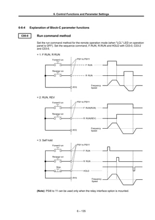
  • 1. 6. Control Functions and Parameter Settings 6-6-4 Explanation of Block-C parameter functions C00-0 Run command method Set the run command method for the remote operation mode (when "LCL" LED on operation panel is OFF). Set the sequence command, F.RUN, R.RUN and HOLD with C03-0, C03-2 and C03-5. = 1: F·RUN, R·RUN PSI1 to PSI11 F・RUN RY0 R・RUN Frequency Speed Reverse run Forward run = 2: RUN, REV PSI1 to PSI11 F・RUN(RUN) RY0 R・RUN(REV) Frequency Speed Reverse run Forward run = 3: Self hold PSI1 to PSI11 F・RUN RY0 R・RUN Stop HOLD Frequency Speed Reverse run Forward run (Note) PSI8 to 11 can be used only when the relay interface option is mounted. 6 – 135
  • 2. PSI1 to PSI11 RY0 6. Control Functions and Parameter Settings C00-1 Run/stop methods C00-2 Jog stop method = 1: Coast to stop = 2: Deceleration stop Coast to stop refers to stopping by turning the output OFF simultaneously with the stop command (F·RUN and R·RUN OFF). Deceleration stop refers to stopping by decelerating to the stopping frequency with the ramp down after the stop command, and then applying the DC-brake to stop. Output frequency Motor speed Output frequency during coast to stop DC brake Ramp down to stop Motor speed during coast to stop RUN (Note) When not using the pick-up function to restart after coast to stop, confirm that the motor is stopped. When not using the pickup function, if the inverter is started while the motor is rotating, the inverter may trip. C00-3 Emergency stop (EMS) input logic Set the input logic of the emergency stop sequence input signal EMS. = 1: Close to stop (when a contact is connected) = 2: Open to stop (when b contact is connected) Select the EMS signal input terminal from the control PCB terminal block PSI to 11, and set with C03-1. (Note) PSI8 to 11 can be used only when the relay interface option is mounted. C00-4 Emergency stop (EMS) mode Set the method of stopping when the emergency stop sequence input EMS turns ON. = 1: Coast to stop, without fault output = 2: Coast to stop, with fault output (When the EMS signal turns ON, the output will be shut off, and FLT will be output.) = 3: Ramp down to stop (without fault output) 6 – 136
  • 3. 6. Control Functions and Parameter Settings C00-5 Control source switchover method (J1 setting) J1 setting =1: OFF =2: ON Select whether to use the sequence input signals from the control PCB terminal block in the local operation mode (when "LCL" LED on operation panel is ON). Refer to section 5-5 for details. C00-6 Control source switchover method (J2 setting) J2 setting =1: OFF =2: ON Select the auxiliary command input when the COP command is ON. Refer to section 5-5 for details. C00-7 Run contact output condition selection The conditions for turning the sequence RUN output ON are set. = 1: ON at pre-excitation (EXC) = 2: OFF at pre-excitation (EXC) C02-0~8 Various setting input selection Refer to section 5-9 for details. C03-0~F Sequence input terminal function − 1 C04-0~F Sequence input terminal function − 2 C05-0~7 Sequence input terminal function − 3 C06-0~A Sequence input terminal function − 4 Refer to section 5-3, 5-6 for details. Refer to the explanation for B06-0 to 6 (ratio interlock bias increase/decrease function) for details on C03-A and C04-9 to A. C07-0~A Analog input terminal function Refer to section 5-7 for details. 6 – 137
  • 4. 6. Control Functions and Parameter Settings C08-0 Auto start (To F・RUN/R・RUN) = 1: OFF (runs with the run command ON after pre-charging) = 2: ON without pick-up If the run command is ON when the power is turned on, run will start after the inverter is charged. (Note 1) Pick-up is not executed with this setting, so if the motor is rotating when the power is turned ON, the inverter operation could trip. ON Output frequency Motor speed Pre-charging Power supply RUN = 3: ON with pick-up If the run command turns ON when the power turns ON, pick-up will start when the inverter charging is completed, and then operation will start. Set this when using momentary restart. (Note 2) The speed can be detected with the IM vector control with sensor and PM motor control (C30-0 f0 = 3, 4). As pickup operation is not carried out, set C08-0 to 2. Output frequency Motor speed Pre-charging (internal RDY) Motor speed search (For V/f control, IM speed sensor-less vector control C30-0 f0 =1,2) Power supply Motor speed RUN (Note 3) If auto start (C08-0 = 2, 3) is used, undervoltage fault will not be detected. 6 – 138
  • 5. 6. Control Functions and Parameter Settings C09-0 Parameter protection Set this parameter to prevent unintentional operations from operation panel. Changing of the data can be protected per function group with the setting value as shown below. (Note 1) Set 2 to prohibit all changes. (Note 2) Set 1 to allow all changes. The 9 setting is for maker maintenance, so do not set it. (Note 3) When using the password number function (when C28-0 is set to 2), this parameter will also be locked. Set U00-1 to the value set with C28-1 to unlock the protection. C09-1 Operation panel lock This setting protects the operation panel FWD, REV and STOP key operations. = 1: All operation possible = 2: All operation prohibited (Note, the motor will stop when the STOP key is pressed for two seconds) = 3: Only STOP key can be operated. C09-2 LCL switchover protection = 1: LCL mode switchover ( LCL SET + STOP keys) during running disabled = 2: LCL mode switchover ( LCL SET + STOP keys) during running enabled (Note) When switching from the local mode to the remote mode, if the terminal block RUN, R.RUN, F.JOG or R.JOG is ON, the mode will not switch even if operation is stopped. C09-3 Reveres run sequence (R·RUN) prohibit C09-4 Reverse run jogging sequence (R·JOG) prohibit = 1: Enable = 2: Prohibit Set this to prevent unintentional reverse run operation. When set to "2", the sequence input "R RUN(R JOG)" operation command will be disabled. Note that if the reverse run setting (negative value) is input into the speed setting during "F·RUN(F JOG)" operation, reverse run will start. 6 – 139 value Block A Block B, C Basic Extn. S/W H/W 1      2 × × × × × 3  × × × × 4  ×  × × 5  ×   × 6      7 ~ 8 × × × × × 9       : Unprotected (changeable) × : Protected (unchangeable)
  • 6. 6. Control Functions and Parameter Settings C09-5 Reverse run during ACR mode prohibit = 1: Enable = 2: Prohibit Set this to prevent unintentional reverse run operation. When set to “2”, reverse run during ACR operation will be prohibited. The reverse run speed will be limited to approx. 1% if reverse run is started. This setting is ignored in the V/f mode. C09-6 Fault history buffer clear The fault history details can be cleared by setting the value to 1 and then pressing LCL SET key. This setting will not be registered in the internal memory. Thus, this parameter must be set each time. Nothing will occur if set to a value other than 1. Use this before handing the unit over to the final user. (Note) The setting values exceeding 2000 are codes for maker maintenance, so do not set. C09-7 Default value load All values per function group are changed to the default values. 9: All default values load (Excluding the maker maintenance parameters) 10: Parameter A 11: Parameters B, C basic functions 12: Parameters B, C extended functions 13: Parameter B software option function Parameter C hardware option function 14: Parameters B basic functions 15: Parameters B extended functions 16: Parameter B software option function 17: Parameters C basic functions 18: Parameters C extended functions 19: Parameter C hardware option function Nothing will occur when values other than the above are set. This parameter setting value will not be registered in the internal memory. (Note) The setting values exceeding 2000 are codes for maker maintenance, so do not set. If set, the following inverter operation may be abnormal. C10-0~7 Custom parameter register Refer to section 4-4 for details on operating these parameters. 6 – 140
  • 7. 6. Control Functions and Parameter Settings C11-0 Default mode setting Set which operation mode the operation panel starts up when the power is turned ON. =1: Local operation mode (LCL) =2: Remote operation mode (RMT) C11-1 Operation command at auto start setting =1: Stop =2: Forward run =3: Reverse run Set the default operation mode at power ON when using the auto start function (C08-0=2, 3) in the local operation mode (operating with the operation panel). For example, if C11-1 is set to 2 and operation is enabled after power ON (sequences RDY1, RDY2, MC are all ON), the forward run will take place. C11-2 Operation panel frequency change operation Set whether to change the frequency and speed setting values in real time. =1: Change setting value in real time =2: Change setting value when set key is pressed C11-3 Display parameter at power ON selection Select the parameters displayed on the operation panel at power ON. Refer to the following diagram. 0. 00. 0 Sub No. Main No. 0 : D block 1 : A block C11-4 LCD panel: Language setting Select the language displayed on the LCD panel. =0: English =1: French =2: German =3: Spanish =4: Italian (Note) This is displayed only when the LCD panel is connected. C11-5 LCD panel: Contrast adjustment Adjust the contrast of the characters displayed on the LCD panel. The character color will darken as a larger value is set. (Note) This is displayed only when the LCD panel is connected. 6 – 141
  • 8. 6. Control Functions and Parameter Settings C11-6 LCD panel: Backlight OFF timer setting Set the time that the LCD panel backlight is ON. Set the ON time with a second unit. If the setting value is "0", the backlight will be ON at all times. (Note) This is displayed only when the LCD panel is connected. C11-7 Operation panel operation mode selection The operation panel parameter operation method can be selected from two methods. Refer to section 4-1-3 Selecting the operation method. C12-0 AI1 terminal input mode selection C12-4 AI2 terminal input mode selection Select the input mode for the AI1 and AI2 terminals. C12-0, 4 = 1 : Voltage input = 2 : Current input Refer to section 5-7 for details on using the analog input terminal. C12-1 AI1 voltage input mode selection C12-5 AI2 voltage input mode selection When the AI1 and AI2 terminal input mode is set to voltage input (C12-0, 4 = 1), set the full scale of these terminal input signals. C12-1, 5 = 1 : 0 to 10V = 2 : 0 to 5V = 3 : 1 to 5V As an example, the relation of the voltage input value and speed setting value when the AI1 and AI2 terminal input function is used for the speed setting is shown below. Refer to Table 5-7-1 for the relation of the analog input value and each setting value when using the input terminal for a function other than speed setting. Setting frequency/Setting speed Max. frequency Max. speed 0 1V C12-1,5=3 C12-1,5=1,2 5V :C12-1=1 10V:C12-2=2 Voltage input mode Input voltage 6 – 142
  • 9. 6. Control Functions and Parameter Settings C12-2 AI1 current input mode selection C12-6 AI2 current input mode selection When the AI1 and AI2 terminal input mode is set to current input (C12-0, 4 = 2), set the full scale of these terminal input signals. C12-2, 6 = 1 : 4 to 20mA = 2 : 0 to 20mA As an example, the relation of the current input value and speed setting value when the AI1 and AI2 terminal input function is used for the speed setting is shown below. Refer to Table 5-7-1 for the relation of the analog input value and each setting value when using the input terminal for a function other than speed setting. 0 4mA C12-2,6=1 C12-2,6=2 20mA Setting frequency/Setting speed Max. frequency Max. speed Current input mode Input voltage 6 – 143
  • 10. 6. Control Functions and Parameter Settings C12-8 AI3 terminal input mode selection C12-9 AI3 input gain Set the full scale of the AI3 terminal analog input signal with C12-8. C12-8 = 1 : -10V to +10V = 2 : -5V to +5V = 3 : +1V to +5V A multiplication gain can be applied on the AI3 terminal input value with C12-9. As an example, the relation of the voltage input value and speed setting value when the AI3 terminal input function is used for the speed setting is shown below. Refer to Table 5-7-1 for the relation of the analog input value and each setting value when using the input terminal for a function other than speed setting. Refer to section 5-7 for details on using the analog input terminals. Setting frequency/Setting speed (Forward run) Max. frequency Max. speed Max. frequency Max. speed -10V : C12-8=1 -5V : C12-8=2 1V C12-8=1,2 C12-8=3 +10V : C12-8=1 +5V : C12-8=2 When running with sequence command R•RUN When running with sequence command F•RUN (Reverse run) C12-3 Filter time constant for AI1 input C12-7 Filter time constant for AI2 input C12-A Filter time constant for AI3 input The filter time constant for the input value of the AI1, AI2 and AI3 terminals can be set. Fluctuation of the setting value caused by input signal noise or chattering, etc., can be suppressed by increasing the time constant. C12-B Program setting filter The program speed and ramp setting are set with the sequence commands S0 to SE, but chattering could occur when these input terminals are changed. In order to avoid this, batch filter processing is performed for S0 to SE. The input signal is validated when the S0 to SE input terminals obtain the same value for longer than the set time, so the program settings will not change for the time set in C12-B after the input is changed. Set C12-B to a time longer than that at which chattering could occur, and lower than the setting delay tolerance time. 6 – 144
  • 11. 6. Control Functions and Parameter Settings C12-C Pulse train input : 0% setting frequency (F1) C12-D Pulse train input : 100% setting frequency (F2) C12-E Pulse train input frequency LPF time constant C12-F Pulse train input judgment time Refer to section 5-7-3 for details related to the pulse train input function. C13-0 A01 terminal output C13-1 A02 terminal output The inverter's internal parameters can be output from the control PCB analog output terminals A01 and A02. C13-7~A Built-in PLC input selection 1~4 The inverter output analog signals can be input to the built-in PLC. Select the details set in memory numbers 10h to 13h. The parameters corresponding to the C13-0,1,7 to A setting values and the full scale of those output signals is shown below. The output voltage and current values are output as a percentage of the full scale. Refer to section 5-8 for details on using the analog output terminals. Refer to section 6-11 for details on using Built-in PLC. The parameters corresponding to the C13-0, 1 setting values and the full scale of those output signals is shown below. The output voltage and current values are output as a percentage of the full scale. Refer to section 5-8 for details on using the analog output terminals. (Note 1) DM1 and DM2 for maker maintenance are to be used only by the maker for maintenance. The user must not set C13-0, 1 to 20 or 21. C13-2 RA-RC output parameters C13-3~5 PSO1, 2, 3 output parameters C13-6 FA-FC output parameters Refer to section 5-6-2 for details. 6 – 145 ValueParameterFull scale11Torque currentMotor rated current × 212Excitation currentMotor rated current × 213Actual motor rotation speedMax. speed14Namp outputRated torque × 215OLT monitor (motor protection)100%16Built-in PLC output 11000h17Built-in PLC output 21000h18Built-in PLC output 31000h19Built-in PLC output 41000h20DM1 for maker maintenance1000h21DM2 for maker maintenance1000h ValueParameterFull scale0Output frequencyMax. frequency1Setting frequency Setting speedMax. frequency Max. speed2Ramp outputMax. frequency Max. speed3Output current (Motor)Motor rated current × 24Output current (Drive)Drive rated current × 25Output voltageMotor rated voltage6Motor output power(Motor rated voltage × Motor rated current) × 27DC voltage200V Series : 300V 400V Series : 600V8OLT monitor (unit protection)100%9Heat sink temperature100°C10Motor speedMax. speed
  • 12. 6. Control Functions and Parameter Settings C13-B Pulse train output function C13-C Pulse frequency at 0% C13-D Pulse frequency at maximum frequency/speed C13-E Pulse train output parameter selection C13-F Output parameter absolute value calculation selection Refer to section 5-8-3 for details on the pulse train output function. C14-7, 8 A01, A02 output method selection C14-0, 1 A01, A02 output gain C14-3, 4 A01, A02 output offset (Voltage) C14-5, 6 A01, A02 output offset (Current) The block diagram for the control PCB analog outputs A01 and A02 is shown below. Internal parameter (Set C13-0) C14-0 (Note 1) C14-3 (Voltage output) C14-5 (Current output) (Note 1) + + AO1 COM Internal parameter (Set C13-1) C14-1 (Note 1) C14-4 (Voltage output) C14-6 (Current output) (Note 1) + + AO2 COM Gain Offset 6 – 146
  • 13. 6. Control Functions and Parameter Settings (Note 1) The maximum output voltage for the A01 and A02 output is approx. 11V. Thus, even if the gain or offset are set to a large value, a voltage higher than this maximum level will not be output. Set the A01, A02 output method with C14-7, 8. C14-7, 8 = 1: Voltage output 0V to 10V = 2: Voltage output 0V to 10V (with 5V offset) = 3: Current output 4mA to 20mA When using A01, A02 for the voltage output (C14-7, 8 = 1 or 2), connect the control PCB A01/A02 L bit (W3, W4) to the voltage mode side. When using for the current output (C14- 7, 8 = 3), set the L bit to the current mode side. Refer to section 5-8 for details on this. When C14-7, 8 is set to 2, the parameter reference point is automatically set to 5V, and the output value gain is set to 0.5-fold. A gain can be applied on the internal parameter value set with C13-0, 1. Set this gain with C14-0, 1. When C14-7, 8 is set to 2 and the output gain is set with C14-0, 1, the gain will be (0.5 × C14-0, 1). Of the parameters selected with C13-0, 1, those shown below are coded with a plus/minus sign. When these parameters are selected, plus or minus can be added by offsetting the output value. Set C14-3, 4 for the voltage output, and C14-5, 6 for the current output. Setting value Parameter Full scale 0 Output frequency Max. frequency 1 Setting frequency Setting speed Max. frequency Max. speed 10 Motor speed Max. speed 11 Torque current Motor rated current × 2 12 Excitation current Motor rated current × 2 13 Actual motor rotation speed Max. speed 14 Namp output Rated torque × 2 An example of setting a 5V offset for the voltage output is shown below. If C14-7, 8 is set to 2, the offset amount when the offset is set with C14-3, 4 becomes (5V + C14-3, 4 setting value). 0V 10V 5V -100% 100% For offset 5V, gain 0.50 Meter output [V] Internal parameter value [%]0V 10V 100%-100% When offset is not set (Offset = 0V, gain = 1.00) Meter output [V] When offset is set Internal parameter value [%] (Note 2) If plus or minus is set with offset, the signal is not output from A01, A02 when the power is shut off, so the output will be 0V (-100% in above example). 6 – 147
  • 14. 6. Control Functions and Parameter Settings C14-2 Random scale display coefficient Set the display value coefficient for the monitor parameter D00-4 (output frequency, speed random scale display) and D01-4 (set frequency, speed, ramp input random scale display. The result of multiplying the output frequency or set frequency, etc., with this setting value is displayed at D00-4, D01-4). C14-9~B AI1, AI2, AI3 random scale coefficient Set the random scale coefficient of the value displayed at monitor parameter D08-0 to 2 (analog input AI1, AI2, AI3 random scale display). 6 – 148