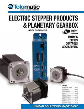
1. ELECTRIC STEPPER PRODUCTS
& PLANETARY GEARBOX
MOTORS
DRIVES
CONTROLS
ACCESSORIES
LINEAR SOLUTIONS MADE EASYLINEAR SOLUTIONS MADE EASY
APEX DYNAMICS
CONTENTS
Stepper Product Features................MRS_2
DS & SI Features.................................MRS_3
DS & SI Specification.........................MRS_5
Software.................................................MRS_6
MRS Motor Dimensions....................MRS_7
HUB Multi-Axis Motion......................MRS_9
MMI Operator Interface..................MRS_11
BOB Breakout Board......................MRS_11
Stepper Prod. Ordering..................MRS_12
2. MRS_2 1.800-328-2174
MRS21
MRS33
MRS22
MRS23
HUB
MMI DS SI
MRS31
MRS32
Stepper Products
stepper product features
Drive DS si
• Self Test
Measures motor para
meters automatically
to optimize system
performance
• Anti-resonance
Achieves higher speeds
and better torque
utilization
• Command Signal
Smoothing
Reduces extraneous
system resonances
• Torque Ripple Smoothing
(Waveform Smoothing)
Adjusts current waveform
to reduce low speed
torque ripple
Motors MRS
• Speeds up to 3,000 RPM
• High resolution (up to
51,200 steps-rev)
• Holding torque
requirements up to 1845
oz-in. (13.03 Nm)
• 2000 line Quadrature
encoder option
• 10 ft. power cables with
connector pre-wired
Multi-axis hub
with i/o HUB
• Networks stepper
products for multi-axis
motion applications
• For real-time execution
of commands down
loaded from a host PC or
PLC using Si™ Command
Language (SCL)
• Programmable for stand-
alone single or multi-axis
operations with Applied
Motion’s easy to use
SiNet Hub Programmer™
Windows software
(software and program
ming cable included)
Operator
interface MMI
• Flush or surface
mounting
• Four line by 20 character
LCD display
• RS232 communication
to SI [STAC6-Si]
controllers
• Enter distances, speeds,
and repeat counts to
pre-assigned variables in
Si™ programming
Application Examples
overview
• Pick and place
• Inspection (camera positioning)
• Painting/stencilling
• Gating
• Parts transfer
• Positioning stops/guides
• Position tables
• Indexing
• Work piece placement
3. www.tolomatic.com MRS_3
Stepper Products
DS & SI DRIVE FEATURES
The DS [STAC6-S] & SI [STAC6-Si] represent the latest
developments in stepper drive technology, incorporating
features that derive the highest performance from today’s
stepper motors. Anti-resonance and waveform damping control
algorithms make them the clear market leader.
nnn Advanced Features
• Self Test
Measures motor parameters automatically to optimize system performance
• Anti-resonance
Achieves higher speeds and better tourque utilization
• Command Signal Smoothing
Reduces extraneous system resonances
• Torque Ripple Smoothing (Waveform Smoothing)
Adjusts current waveform to reduce low speed torque ripple
• Microstep Emulation
Smooth, high resolution motion in any application
nnn Features
• Current Output 0.5 to 6.0 A
• 90-135 VAC Input, 50/60 Hz
(for other voltages, contact Tolomatic)
• 167V Bus
• Set-up and configuration software
• Configurable Idle current reduction
• External control options
• Pulse and Direction
• Analog Command Signal
• Host command via RS232/485.
• Integral control options -
Si Programmer™ - intuitive easy to use graphical programming
language.
Basic drive; analog, digital
and host command input.
• Pulse & direction with
microstep emulation
• A/B Quadrature
pulse with electronic
gearing
• CW and CCW pulse
• Multi-axis function
ality if used with a
HUB [SiNet Hub]
• “Host” commands for
real time control from
a host PC or PLC
using RS-232 or
RS-485 serial
communication.
• Velocity control mode with
fixed rate, proportional
analog, and joystick
compatibility
Controller/drive; single axis
indexer/drive.
• SI [STAC6-Si] can be
programmed for stand-alone
operation with the easy
to use Si Programmer™
Windows®
software with
integrated motor set-up
(software and programming
cable included).
• Graphical point and click
format combines motion,
I/O, and operator interface
functionality for simple
machine sequencing.
• SI [STAC6-Si] can be set-up
for Q programming with
register manipulation, con-
ditional processing, math
functions, and multi-task-
ing using a comprehensive
programming language.
DS SI
Please note the Tolomatic ordering codes. Use these codes when ordering stepper components from Tolomatic
(Applied Motion Products model equivalents appear in [brackets])
[ ] [ ]
4. MRS_4 1.800-328-2174
Stepper Products
nnn MicroStep Emulation
nnn Command Signal Smoothing
nnnTorque Ripple Smoothing (wave form smoothing)
nnn Anti-Resonance
nnn Self Test
nnn Encoder Feedback Functions
DS & SI ADVANCED FEATURES
With Microstep Emulation, systems that have a need to use low step resolutions
can still provide smooth motion. The drive takes the step count and creates
microsteps which are fed to the motor.
As an example, this could be used on a retrofit system where the controller
resolution is fixed at a low value and cannot easily be changed.
Dynamic smoothing can soften the effect of immediate changes in velocity and
direction, making the motion of the motor less jerky. An added advantage is that
this can reduce the wear on mechanical components.
All step motors have an inherent low speed torque ripple that can effect the
motion of the motor. By analyzing this torque ripple, the system can apply a
negative harmonic to negate this effect. This gives the motor much smoother
motion at low speed.
Step motors tend to “resonate” at some frequency. By entering system data, this
natural frequency can be calculated and a damping term entered into the control
algorithm. This significantly improves the midrange stability and allows the motor
to achieve higher speeds and make more use of the available torque.
At start-up, the drive measures the motor parameters, including the resistance
and inductance, then uses this information to optimize the system performance.
It also compares this information from the last start-up and checks to see if the
motor data has changed. This could indicate a fault or system change. The drive
can also detect open and short circuits and incorrect motor wiring.
With the addition of an encoder on the motor the DS [STAC6-S] & SI [STAC6-Si]
can provide additional functions.
• Stall Detect - The drive detects if the motor has stalled and triggers the fault
output.
• Stall Prevention - Prevent motor stalls before they occur by allowing the
drive to automatically reduce motor speed to optimize torque.
1.8o
Steps
Synthesized
Microsteps
Demanded Torque
Actual Torque
5. www.tolomatic.com MRS_5
Stepper Products
(SI STAC6-Si pictured)
DS & SI technical specifications
nnn features summary nnn dimensions
POWER AMPLIFIER Specifications
AMPLIFIER TYPE MOSFET, Dual H-Bridge, 4 Quadrant
CURRENT CONTROL 4 state PWM at 20 Khz
OUTPUT CURRENT 0.5— 6.0 in 0.01 amp increments
POWER SUPPLY Line Operated Nominal 120 VAC, 50/60 Hz
DC BUS VOLTAGE Nominal 165 VDC
AC INPUT VOLTAGE 90—135 VAC, 50/60 Hz (for other voltages, contact Tolomatic)
PROTECTION Over-Voltage, Under voltage, Over-Temp, External Output Shorts (Phase-to-Phase, Phase-to-Ground), Internal Amplifier Shorts
IDLE CURRENT REDUCTION Reduction to any integer percent of full-current after delay selectable in milliseconds.
MOTOR REGENERATION Built in regeneration circuit - 50 watts max.
CONTROLLER SPecifications
NON-VOLATILE STORAGE Configurations are saved in FLASH memory aboard the DSP
Mode of Operation Step & Direction, CW/CCW, A/B Quadrature pulse, stored program, Joystick
STEP AND DIRECTION INPUTS Optically Isolated: 5 Volt. Minimum pulse width = 200 ns. Maximum pulse frequency = 2 MHz
SPEED RANGE Depends upon application. Amplifier is suitable for speeds up to 133 rps
RESOLUTION Software selectable from 200-to-51200 steps/rev in increments of 2 steps/rev
ANTI RESONANCE Raises the system damping ratio to eliminate midrange instability allowing stable operation to 50 rps or greater
TORQUE SMOOTHING Allows for fine adjustment of phase current waveform harmonic content to reduce low-speed torque ripple in the range 0.25 — 1.5 rps
AUTO SETUP Measures motor parameters automatically
SELF TEST Identifies the presence of an encoder and determines resolution. Diagnoses miswires and open phases
MICROSTEP EMULATION Performs low resolution stepping by synthesizing fine microsteps from coarse steps
ENCODER OPTION Employs encoder to provide failsafe stall detect
INTERFACE RS-232 and RS-485 Bus
ENCODER Differential line receivers suitable for 200 KHz or greater
AMBIENT TEMPERATURE 32- 158° F (0 to 70° C)
HUMIDITY 90% non-condensing
DS SI
[STAC6-S] [STAC6-Si]
Hub 4 4
Command Inputs Pulse and Direction 4
CW and CCW Pulse 4
Master Encoder 4
Command Modes Host Command Language 4 4
Si Indexer 4
Logic Input Functions Enable 4
Limit Switches 4 4
Alarm Reset 4 4
Logic Output Functions Alarm 4 4
Brake 4 4
Motion 4 4
Analog Inputs 4
Digital Inputs 7 15
Digital Outputs 3 7 4.657" (118mm) 2.31" (59mm)
7.36"
(187mm)
IN/OUT1
IN/OUT2
PC/MMI
Status
ACPower
G
N
L
Encoder
[STAC6-S]
or
[STAC6-Si]
Please note the Tolomatic ordering codes. Use these codes when ordering stepper components from Tolomatic
(Applied Motion Products model equivalents appear in [brackets])
6. MRS_6 1.800-328-2174
Stepper Products
Configurator™ & Si Programmer™ Software
Si Programmer™ Software
The SI [STAC6- Si] is designed to be both configured and programmed through
software. Virtually all the SI’s [STAC6- Si] functions are controlled by software.
The Si Programmer™ software that comes with the drive allows setting the motor
current, the step resolution, jogging parameters and limit switch polarity. It also
allows the writing of complex motion control and machine interaction programs.
Set-up and configuration Software
The A.M.P. [Applied Motion Products] CONFIGURATOR™ software simplifies the setup and
configuration of the DS [STAC6- S] & SI [STAC6- Si] . Click on the icon representing the
aspect of the drive that needs changing and an intuitive dialog box will open. Configuration
data for A.M.P. recommended motors is available from a drop down menu.
Input / Output Monitor screen capture
Motor selection screen capture
Instruction/Tool menu
On screen MMI emulation
7. www.tolomatic.com MRS_7
Stepper Products
Please note the Tolomatic ordering codes. Use these codes when ordering stepper components from Tolomatic
(Applied Motion Products model equivalents appear in [brackets])
mrs2 23-frame step motors
nnn Specifications nnn torque curves
nnn dimensions
1.86 (47.14)
1.86
(47.14)
.93
(23.57)
.93
(23.57)
2X .23 [±.006]
(5.8)
4X ø.20 [±.01]
(5.0)
ø1.50
(38.1)
ø.25 [+.0000]
[-.0005]
(6.35)
ø.25 [+.0000]
[-.0005]
(6.35)
.02 x 1.77 (.5 x 45)
BOTH SHAFTS.81 [±.02]
(20.6)
.63 [±.04]
(16)
.59 [±.01]
(15)
LABEL
.20
(5.0)
.06 [±.008]
(1.6)
LENGTH “L”
1.11
(28.2)
1.11
(28.2)
2X 2.22 (56.4)
2X 2-56 UNC
.19 (5) DEEP ON A
ø1.28 (32.5) B.C.
2X 2-56 UNC TAP
THRU 180° APART
ON A ø.750 (19.05) B.C.
120
(3048)
MIN.
.59 [±.01]
(15)
MRS21 [HT23-548D]
MRS23 [HT23-550D]
MRS22 [HT23-549D]
MRS21 [HT23-548D]
MRS22 [HT23-549D]
MRS23 [HT23-550D]
0
50
100
150
200
250
MRS22 [HT23-549D]
MRS23 [HT23-550D]
MRS21 [HT23-548D]
1 2 4 86 10 15 20 30 40 500.5
REVS PER SECOND
TORQUE(oz.-in.)
Holding rated rotor
Order a.m.p. TORQUE CURRENT RESISTANCE INDUCTANCE INERTIA
Code Model oz-in A Ohms mH oz-in2
MRS21 [HT23-548D] 60 1.5 3.4 6 .65
MRS22 [HT23-549D] 118 1.4 4.2 12.8 1.64
MRS23 [HT23-550D] 181 2.9 5.1 15.2 2.62
Ratings are with motor connected in series
Order a.m.p. LENGTH “L”
CODE MODEL in. mm
MRS21 [HT23-548D] 1.71 43.4
MRS22 [HT23-549D] 2.19 55.6
MRS23 [HT23-550D] 3.05 77.5
8. MRS_8 1.800-328-2174
Stepper Products
mrs3 34-frame step motors
nnn Specifications nnn torque curves
nnn dimensions
Length“L”
0
250
500
750
1000
1250
1500
1 2 4 86 10 15 20 30 40 500.5
REVS PER SECOND
TORQUE(oz.-in.)
MRS32 [HT34-489D]
MRS33 [HT34-490D]
MRS31 [HT34-488D]
MRS31 [HT34-488D]
MRS33 [HT34-490D]
MRS32 [HT34-489D]
MRS31 [HT34-488D]
MRS33 [HT34-490D]
MRS32 [HT34-489D]
Holding rated rotor
ORDER A.m.p. TORQUE CURRENT RESISTANCE INDUCTANCE INERTIA
CODE Model oz-in A Ohms mH oz-in2
MRS31 [HT34-488D] 650 5.1 1.6 5.2 7.8
MRS32 [HT34-489D] 1200 5.1 1.7 .88 14.6
MRS33 [HT34-490D] 1845 5.8 1.7 .96 21.9
Ratings are with motor connected in series
ORDER a.m.p. DIA. “D” LENGTH “H” LENGTH “K” LENGTH “L”
CODE Model in. mm in. mm in. mm in. mm
MRS31 [HT34-488D] .5 12.7 .556 14.12 .125 3.18 3.11 79.0
MRS32 [HT34-489D] .5 12.7 .556 14.12 .125 3.18 4.63 117.6
MRS33 [HT34-490D] .625 15.88 .705 17.91 .1875 4.763 6.14 155.9
9. www.tolomatic.com MRS_9
Stepper Products
hub Multi-Axis motion hub with i/o
Description
The HUB [SiNet Hub444] allows up to 4 stepper drives to be
controlled in host mode from a single PC, a PLC’s RS-232
serial port, or run in stand-alone mode. Each indexer-drive
acquires its address from the port to which it is connected.
This simple addressing scheme minimizes drive set-up and
configuration time. Connections are made with low-cost,
reliable (RJ11) telephone cabling.
The HUB [SiNet Hub444] is powered by the drive that is
connected to port #1, saving you the cost and installation
expense of using a separate power supply. Si™ Command
Language (SCL) allows a host PC or PLC to execute relative,
absolute and homing moves, make status inquiries, sample
inputs, set outputs, and more.
SiNet Programmer Windows®
software allows the user to
create and store multi-axis motion control programs in the
HUB [SiNet Hub444] and run them without a PC. This function
allows the user to create a multi-axis motion system controlled
from an operator interface or trigger.
If your application requires multiple axes to operate in “host
mode” you can connect any programmable drive directly to
your PC via the HUB [SiNet Hub444] and invoke the Si™
Command Language (SCL).
Features:
• Networks stepper products for multi-axis motion applications
• For real-time execution of commands downloaded from a
host PC or PLC using Si™ Command Language (SCL)
• Programmable for stand-alone single or multi-axis operations
with Applied Motion’s easy to use SiNet Hub Programmer™
Windows software (software and programming cable
included)
• Communication via RS232
• Four optically-isolated programmable inputs
• Four optically-isolated programmable outputs
• DIN rail mounting
Please note the Tolomatic ordering codes. Use these codes when ordering stepper components from Tolomatic
(Applied Motion Products model equivalents appear in [brackets])
10. MRS_10 1.800-328-2174
Stepper Products
hub Multi-Axis motion hub with i/o
1
2
3
4
PC-MMI
INHUB 444 OUT
4.2 (106.7)
0.156 (3.96) dia mounting holes [4]
3.9 (99.1)
2.85
(72.4)
2.55
(64.8)
.670
(17.02)
max
.062 (1.57)
nnn technical specifications
Power Power is provided by Si indexer-drive on Port 1. Provides up to 50 mA for MMI via PC/MMI port
Communication Ports 1 - 4: RS232, 9600 bps, 8 data bits, one stop bit, no parity
MMI: same
PC in router mode: same
PC when running SiNet Hub Programmer™ software: 19200 bps
Max cable length, any port: 50 feet
Physical Constructed on .062” fiberglass printed circuit board with 4 .156” mounting holes (nylon spacers included).
4.2” x 2.85” x 0.72”
Two red LEDs
Operating temperature range: 0 - 70° C
DIN rail mounting (fits ENS0022 35 mm rail)
Program Move distances: +/- 16,000,000 steps
Move speeds: .025 to 50 rev/sec
Accel/Decel range: 1 to 3000 rev/sec/sec
Time delays: .01 to 300 seconds
Loop counts: 1 to 65,535
Number of nested loops: unlimited
Number of subroutines: unlimited
Subroutine stack depth: 5 calls maximum
Number of comments: limited only by 200 line program length
MMI variables for storing speeds, distances and loop counts entered by operator: 50
Maximum size of messages displayed by an MMI Prompt: 60 characters (80 for an MMI Menu instruction)
Maximum total size of all MMI Prompt messages: 1500 characters
Steps/revolution: 2,000 - 50,800
Connectors RJ11 for drives and PC/MMI. Screw terminals for programmable inputs and outputs. Accept AWG 16-28 wire
Programmable Inputs Optically isolated, 2200 ohms internal impedance, 5–24 VDC.
Programmable Outputs Optically isolated (photo darlington), 28 VDC max, 100 mA max.
nnn Dimensions nnn block diagram
11. www.tolomatic.com MRS_11
Stepper Products
MMI Operator interface
bob break out board
User interaction with the SI [STAC6-Si] is simple with the
MMI operator interface. Software allows visual setup of the
panel to show a particular action taking place, it prompts the
user to make a decision, or provides information such as move
distance, move speed, repeat count.
Features
• Flush or surface mounting
• Four line by 20 character LCD display
• Uses (RJ11) telephone cable with SI [STAC6-Si] controllers
• Enter distances, speeds and repeat counts to pre-assigned
variables in SI [STAC6-Si].
Cables
Motor cable and encoder cable are included when ordering
SI [STAC6-Si] controllers. User supplies (RJ11) telephone
cables.
Unless otherwise noted, all dimensions shown are in inches (Dimensions in parenthesis are in millimeters)
nnn Dimensions
Break Out Boards BOB for the DB25 I/O connectors of a DS
[STAC6-S] & SI [STAC6-Si] drive are available. Each Break out
board comes with a 1 foot extension cable and a din-rail mountable
terminal strip to make connecting the I/O points of a
DS [STAC6-S] & SI [STAC6-Si] drive easier.
BOB1 is for the IN/OUT1 connector of DS [STAC6-S] &
SI [STAC6-Si] drives.
BOB2 is for the IN/OUT2 connector of SI [STAC6-Si] drive only.
Please note the Tolomatic ordering codes. Use these codes when ordering stepper components from Tolomatic
(Applied Motion Products model equivalents appear in [brackets])
12. MRS_12 1.800-328-2174
Stepper Products
ordering
mrs 23 si enc ghs205 hub mmi bob1 bob2
nnn MOTOR TYPE
order description
MRS Stepper Motor
nnn multi-axis applications
order description
HUB Multi-Axis Motion Hub with I/O [SiNet Hub 444]
(RJ11) telephone cables included
nnn MOTOR SIZE / DRIVE SIZE
order A.M.P. FRAME STACK
code model SIZE SIZE
21 [HT23-548D] 23 1
22 [HT23-549D] 23 2
23 [HT23-550D] 23 3
31 [HT34-488D] 34 1
32 [HT34-489D] 34 2
33 [HT34-490D] 34 3
Once motor type and frame size is selected, the
appropriate adapter and couplers required are
automatically chosen for assembly onto actuator.
Specify one of these five codes
Drive choice
DS Stepper Drive [STAC6-S]
order BOB1 for cables
SI Controller/Stepper Drive [STAC6-Si]
order BOB1 & BOB2 for cables
MOTOR Only
XX Motor Only
customer MOTOR Options
XY* Customer supplied motor(s) shipped to Tolomatic
for mounting. Tolomatic to mount using standard
hardware and couplers
XJ* Motor(s) supplied and mounted by customer,
Tolomatic to furnish standard hardware and
couplers
* For XY and XJoptions, a full endface and
shaft dimensional drawing must accompany the
order for the actuator. Customer motors must be
directly interchangeable with Tolomatic motors.
nnn Planetary Gearbox REDUCTIONS*
[For LMI (Screw-drive inline) or SDL & SDR (Belt-drive
direct-drive) mounting only]
order [apex] INPUT MOTOR REDUCTION
code Model dia. frame size RATIO
GHS205 AN23 1/4-inch 23 5 : 1
GHS210 AN23 1/4-inch 23 10 : 1
GHS305 AN34 1/2-inch 34 5 : 1
GHS310 AN34 1/2-inch 34 10 : 1
nnn USER INTERFACE
MMI Operator interface (for use with SI)
nnn break out board
BOB1 Break out board & cable (for use with DS & SI)
BOB2 Break out board & cable (for use with SI)
NOTE: for SI it is recommended to order BOB1 also.
nnn Encoder
ENC Encoder (converts rotary motion to code of
electronic pulses); 10ft. (3m) cable
Not all codes listed are compatible with all options
Use the Tolomatic sizing and selection software to determine available options and
accessories based on your application requirements
User manuals and software CD-ROM is included with any controller or drive ordered.
Manuals and software are also available for download at www.tolomatic.com
Consult Tolomatic to select or purchase individual components, not part of a system
After the ordering codes for the Tolomatic actuator have been entered, the ordering codes for the
stepper products will follow.
*See Tolomatic
Planetary Gearbox
publication
#3600-4161 or
www.tolomatic.
com for complete
information
Ordercode Part NO. A.m.p.model DESC.
MRS21 3604-1600 [HT23-548D] Motor
MRS22 3604-1601 [HT23-549D] Motor
MRS23 3604-1602 [HT23-550D] Motor
MRS31 3604-1603 [HT34-488D] Motor
MRS32 3604-1604 [HT34-489D] Motor
Ordercode Part NO. A.m.p.model DESC. Ordercode Part NO. A.m.p.model DESC.
MRS33 3604-1605 [HT34-490D] Motor
DS 3604-0030 [Stac6-S] Drive
SI 3604-0031 [Stac6-Si] Drive/Controller
ENC 3604-1606 – 23 Frame Encoder
ENC 3604-1607 – 34 Frame Encoder
– 3604-1608 – Encoder Cable
HUB 3604-1612 [SiNetHub444] Multi-Axis Hub
BOB1 3604-1609 – Breakout Block DS/SI
BOB2 3604-1610 – Breakout Block SI
3604-1611 – Breakout Cable
nnn Part numbers

![MRS_2 1.800-328-2174
MRS21
MRS33
MRS22
MRS23
HUB
MMI DS SI
MRS31
MRS32
Stepper Products
stepper product features
Drive DS si
• Self Test
Measures motor para
meters automatically
to optimize system
performance
• Anti-resonance
Achieves higher speeds
and better torque
utilization
• Command Signal
Smoothing
Reduces extraneous
system resonances
• Torque Ripple Smoothing
(Waveform Smoothing)
Adjusts current waveform
to reduce low speed
torque ripple
Motors MRS
• Speeds up to 3,000 RPM
• High resolution (up to
51,200 steps-rev)
• Holding torque
requirements up to 1845
oz-in. (13.03 Nm)
• 2000 line Quadrature
encoder option
• 10 ft. power cables with
connector pre-wired
Multi-axis hub
with i/o HUB
• Networks stepper
products for multi-axis
motion applications
• For real-time execution
of commands down
loaded from a host PC or
PLC using Si™ Command
Language (SCL)
• Programmable for stand-
alone single or multi-axis
operations with Applied
Motion’s easy to use
SiNet Hub Programmer™
Windows software
(software and program
ming cable included)
Operator
interface MMI
• Flush or surface
mounting
• Four line by 20 character
LCD display
• RS232 communication
to SI [STAC6-Si]
controllers
• Enter distances, speeds,
and repeat counts to
pre-assigned variables in
Si™ programming
Application Examples
overview
• Pick and place
• Inspection (camera positioning)
• Painting/stencilling
• Gating
• Parts transfer
• Positioning stops/guides
• Position tables
• Indexing
• Work piece placement](data:image/gif;base64,R0lGODlhAQABAIAAAAAAAP///yH5BAEAAAAALAAAAAABAAEAAAIBRAA7)