SlideShare a Scribd company logo
1 of 15
3. Test Operation and Adjustment
3-4-4 Magnetic pole position estimation function and test operation for PM motor with
sensor control (C30-0 f0 = 4)
CAUTION
This function can be used only with a system that drives a PM motor and which the motor is locked
with mechanical brakes when stopped.
Refer to Section 3-4-3 for all other cases.
(1) Before adjusting magnetic pole position estimation function
For PM motor with sensor control, the speed detection option is required in addition to the VAT300
standard unit.
When using the PM motor control mode, use with FWD, F.RUN as forward run and Rev, R.RUN as
reverse run.
With the VAT300, the counterclockwise rotation (CCW) looking from the motor shaft is defined as
forward run, and clockwise rotation (CW) is defined as reverse run.
Forward run (CW) Reverse run (CW)
Fig. 3-4-4-a Definition of VAT300 motor rotation direction
Refer to Table 3-4-4-a, and confirm that the speed detection option compatible with the encoder in
use has been prepared. Refer to Chapter 7 for details on the speed detection option.
Table 3-4-4-a
Encoder type Speed detection option (Instruction Manual No.)
A, B, Z phase signals
U30V24DN1 (PCST-3480)
U30V24DN2 (PCST-3481)
U30V24DN3 (PCST-3482)
U30V24DN4 (PCST-3483)
(2) Outline of magnetic pole position estimation function
The magnetic pole position estimation function is a special function for driving the PM motor with an
incremental encoder has only the A, B, Z phase signals instead of the U, V, W signals or absolute
value signals. This function searches for the stopped PM motor's magnetic pole position in approx.
two seconds when starting operation for the first time after turning the power ON.
After the motor starts running, the estimated magnetic pole position information is used for several
rotations until the encoder's correct Z phase signal is detected. Once the Z phase signal is detected,
the motor runs using that Z phase signal as a reference. If a fault occurs, the magnetic pole position
is estimated again when operation starts again.
It may be necessary to adjust the magnetic pole position estimation function depending on the PM
motor being used. When B19-0 is set to 7, the magnetic pole position estimation adjustment mode
which executes the magnetic pole position estimation operation only once is enabled. Adjust the
magnetic pole position estimation with this mode before starting the motor operation.
(Note) The parameters are not automatically adjusted just by setting B19-0 to 7 and pressing the
and keys. This mode executes magnetic pole position estimation operation just once for
adjustment purposes.
3 – 41
3. Test Operation and Adjustment
CAUTION
Precautions for executing magnetic pole position estimation adjustment mode
(PM motor control)
β€’ Do not carry out maintenance, such as wiring or mounting the option PCB while the PM motor is
running. Even if the inverter power is not turned ON, the PM motor could rotate by the connected
load or machine and cause a high voltage to be generated in the motor terminals. If the PM motor is
connected to the inverter, the inverter could be powered when the PM motor rotates.
Confirm that the PM motor is fixed with brakes before starting wiring work, etc.
β€’ Before mounting the PCB for the speed detection option onto the control PCB, always turn the
inverter power OFF and wait at least 10 minutes. Confirm that all displays on the operation panel are
OFF and that the "CHARGE" LED in the unit is OFF before starting the mounting work.
Note that the main circuit terminals are charged to a high voltage.
β€’ Always ground the motor and inverter.
β€’ Always confirm the safety around the motor before starting the magnetic pole position estimation
adjustment.
β€’ The magnetic pole position estimation adjustment mode can be executed only in the local operation
mode.
Confirm that the "LCL" LED on the operation panel is ON.
β€’ If magnetic pole position estimation operation does not end properly, always turn the inverter power
OFF before investigating and confirming the state.
β€’ The contact output FLT will activate if magnetic pole position estimation ends abnormally.
In equipment that uses this contact, keep the operation of the related devices in mind.
β€’ After setting the parameters or after adjusting the magnetic pole position estimation, do not move
the position at which the encoder is fixed onto the motor, or interchange the motor's U, V, W phase
wires.
3 – 42
3. Test Operation and Adjustment
(3) Adjusting magnetic pole position estimation function
Carry out automatic tuning with the following procedures.
Refer to Chapter 4 for details on using the operation panel.
(1) Preparation
(2) Turn power ON, start VAT300
(3) Selecting the control mode
(Set C30-0)
(4) Initialization of motor ratings and constants
(5)Setting the ASR and ACR parameters
(6) Setting the encoder parameters
(7) Adjusting the magnetic pole position estimation function
End of adjustment
Procedures for adjusting the magnetic
pole position estimation function
Fig. 3-4-4-b Procedures for adjusting magnetic pole position estimation function for PM motor
control
1) Preparation (Before turning the power ON)
Confirm that the motor is locked with mechanical brakes.
Confirm at the speed detection option PCB is correctly mounted on the control PCB, and that
the encoder signal wire is correctly connected to the speed detection option. Refer to the
instruction manual of the speed detection option being used for details on connecting the
encoder signal wire.
2) Turning the power ON and starting VAT300
Turn the power ON.
(In the case of U30V24OP1)
After carrying out an initial check of the operation panel for
approx. 5 seconds, the display changes as shown on the right.
The "LCL" LED also turns ON.
(In the case of U30V24OP2)
All LEDs on the numeric display will turn ON for a short time, and
then " ", " " and " " will appear.
The "LCL" and "Hz" LEDs will also turn ON.
(Note) When the power is turned ON next (after setting C30-0 f0 = 4), "D00-2" will appear on
the display, and the "Hz" LED will not light. This is because the mode is set to the PM
motor vector control mode.
3 – 43
Hz
A
οΌ…
LCLFWD REV FLT
Out put f r e que nc y
D00- 0 OFF. Hz
FWD REV FLT LCL
3. Test Operation and Adjustment
3) Selecting the control mode
β€’ Set A05-2 to 1. (Set the hardware option function display ON.)
β€’ Set the control mode selection: C30-0 f1 f0.
This parameter must be set first.
PM motor with sensor control mode is to be used, so set C30-0 f0 = 4.
Set c30-0 f1 f0 as shown below according to the load.
Normal overload setting: C30-0 f1 f0 = 1 4
Heavy overload setting : C30-0 f1 f0 = 2 4
(Note 1) The default value is set to V/f control and normal overload setting (C30-0=11), so
always change C30-0.
(Note 2) If the fault "SP-5" occurs when the C30-0 setting is changed, the following causes
can be considered.
β€’ The speed detection option is not mounted correctly.
β€’ The encoder signal wire is not connected correctly, or is broken
Turn the inverter power OFF and check the state.
4) Initialization of motor rating and motor constants
Input the parameters required for PM motor control. Set the parameters shown in Table 3-4-4-b.
Table 3-4-4-b
Parameter No. Name
B01-0
B01-1
B01-2
B01-3
B01-4
B01-5
B01-6
B01-7
B01-8
Rated input voltage setting [No.]
Motor rated output [kW]
No. of motor poles [Pole]
Rated output voltage [V]
Max. speed [minβˆ’1
]
Base speed [minβˆ’1
]
Motor rated current [A]
Carrier frequency
No. of encoder pulses [P/R]
B03-0
B03-1
B03-2
B03-3
B03-4
R1: PM motor primary resistance (Mantissa section) [mΩ]
R1: PM motor primary resistance (Exponent section)
Ld: PM motor d axis inductance (Mantissa section) [mH]
Lq: PM motor q axis inductance (Mantissa section) [mH]
Ld, Lq: PM motor inductance (Exponent section)
* The max. speed cannot be set below the base speed, and the base speed cannot be set above
the max. speed.
5) Setting the ASR and ACR parameters
Do not change the ASR (speed control) and ACR (current control) parameters shown in Table 3-
4-4-c from the default values before adjusting the magnetic pole position.
Note that A10-1 must be set to the value obtained with the following expression.
Table 3-4-4-c
Parameter No. Name Standard value
A10-0
A10-1
A10-2
A10-3
A10-4
ASR response
Machine time constant
Integral time constant compensation coefficient
ASR drive torque limiter
ASR regenerative torque limiter
10.0 [rad/s]
1000 [s]
100 [%]
100 [%]
100 [%]
A20-0
A20-1
ACR response
ACR time constant
1500 [rad/s]
10.0 [ms]
3 – 44
3. Test Operation and Adjustment
Refer to the following expression, and set the A10-1: machine time constant setting to match the
inertia of the entire load connected with the PM motor. The machine time constant (Tm) refers to
the time required to accelerate to the base rotation speed from the zero speed at the rated
torque.
Tm [ms] = 10.97 Γ— J [kgβ€’m2
] Γ— (Nbase [min-1
])2
/ Power [W]
J : Total inertia [kgβ€’m2
] ( = 1/4 Γ— GD2
[kgfβ€’m2
])
Nbase : Base rotation speed [min-1
]
Power : Motor rated output [W]
6) Setting the encoder parameters
The encoder parameters shown in Table 3-4-4-d must be set.
Table 3-4-4-d
Parameter
No.
Name
C50-2 Encoder AB advance direction selection
C50-3 Encoder ABZ pulse type selection
C51-0 Encoder selection
C51-1 AB phase-Z phase type selection
C51-2 Encoder Z signal reversal
C51-4 Z-IN β†’ U phase winding phase angle
The method for setting each parameter is shown below. Set these in order.
[1] C51-0: Encoder selection
Use the default value when using the magnetic pole position estimation function.
[2] C50-2: Encoder AB advance direction selection
With the VAT300, the rotation in the counterclockwise direction (CCW) looking from
the motor shaft is defined as forward run, and in the clockwise direction (CW) is
defined as reverse run. Determine this parameter’s setting value according to the
phase relation of the encoder AB phase signals during forward run.
A phase
B phase
(a) When C50-2=1
A phase
B phase
(b) When C50-2=2
Time Time
Fig. 3-4-2-c Encoder AB advance direction selection
(Note) If C50-2 is set to 2, set C50-3 to 0.
[3] C51-1 : AB phase-Z phase type selection
[4] C51-2 : Encoder Z signal reversal
With the VAT300, the four patterns shown in Fig.-3-4-3-c are estimated for the A, B and Z
phase pulse encoder signals.
C51-1 is set based on the phase relation of the A phase signal's rising edge and the Z phase
signal. With this setting and at a time of reverse running, the A phase signal's down edge during
the Z phase being high is the zero point.
To generate the A phase signal rising edge when the Z phase signal is High (Fig. (a)), set C51-1
to 0. In this case, the A phase signal rising edge will be the zero point (magnetic pole position).
In all other cases, set C51-1 to 1. In this case, the Z phase signal's rising edge will be the zero
point. (Fig. (b)). In this case, the Z phase rising edge is the zero point even at a time of the
reverse running.
If the Z phase signal needs to be reversed to match the following signal definition, set C51-2 to
1.
3 – 45
3. Test Operation and Adjustment
Zero point
A phase
B phase
(a) When C51-1=0 (during CCW rotation)
A phase
B phase
(b) When C51-1=1 (during CCW rotation)
Time Time
Zero point
Z phase Z phase
Zero point
A phase
B phase
(c) When C51-1=0 (during CW rotation)
A phase
B phase
(d) When C51-1=1 (during CW rotation)
Time Time
Zero point
Z phase Z phase
Fig. 3-4-4-d A, B and Z phase pulse encoder signals
(Note) If C51-2 is set to 1, set C50-3 to 0.
[5] C50-3 : Encoder ABZ pulse type selection
Only when using an encoder with signal specifications that cannot be handled with the C50-2
and C51-2 settings, set C50-3 to reverse or interchange the signals.
The signal conversion circuit will function with the combination shown in the table below
according to the C50-3 setting value.
(Note) Set C50-3 to 0 (no signal reversal/interchange) when C5-2 and C51-2 have been set.
C50-3
setting
value
A-IN forward/
reverse run
B-IN forward/
reverse run
Z-IN forward/
reverse run
AB inter-
change
0 – – –
No inter-
change
1 Reverse – –
2 – Reverse –
3 Reverse Reverse –
4 – – Reverse
5 Reverse – Reverse
6 – Reverse Reverse
7 Reverse Reverse Reverse
8 – – –
AB inter-
change
9 Reverse – –
10 – Reverse –
11 Reverse Reverse –
12 – – Reverse
13 Reverse – Reverse
14 – Reverse Reverse
15 Reverse Reverse Reverse
[6] C51-4: Z-IN β†’ U phase winding phase angle
This can be automatically adjusted with automatic tuning when the motor can be run in an
isolated state without a load connection. Release the external brakes, and refer to Section 3-5-3
and carry out step 7 and following of the Fig. 3-4-3-c flow chart.
In other cases, this parameter is adjusted after the magnetic pole position estimation function
has been adjusted. Proceed to adjustment of the magnetic pole position estimation.
3 – 46
Fig. 3-4-4-e Signal conversion circuit
AB interchange
Reverse
A- IN1
B- IN1
Z- IN
A phase signal
B phase signal
Z phase signal
3. Test Operation and Adjustment
7) Adjusting the magnetic pole position estimation function
The magnetic pole position estimation function is adjusted.
[1] Select the magnetic pole position estimation mode with the magnetic pole position estimation
selection (B39-0 f0).
When the magnetic pole position estimation function is used, normally f0 = 2 should be
selected.
If the motor has a reverse inductance (Ld<Lq), select f0 = 3.
(Refer to Section 6-9 for an explanation on the PM motor circuit constant.)
Select f0 = 3, when not using a magnetic pole position estimation function, or when you stop
use.
[2] When B19-0 is set to 7 and the LCL
SET
key is pressed, the magnetic pole position estimation
mode which executes the magnetic pole position estimation operation once will start.
To carry out the same operation again, repeat the above step.
When the magnetic pole position estimation function starts normally, the operation will end in
approx. two seconds.
(Note) The parameters are not automatically adjusted just by setting B19-0 to 7 and pressing
the and keys. This mode executes magnetic pole position estimation
operation just once for adjustment purposes.
[3] Adjust the magnetic pole position estimation function
The parameters required for adjusting the magnetic pole position estimation function are shown
in Table 3-4-4-e. The parameters which indicate the magnetic pole position estimation results
are shown in Table 3-4-4-f.
Table 3-4-4-e
Parameter No. Name
B39-1 Magnetic pole position estimation voltage
B39-2 Magnetic pole position estimation time
B39-3 Voltage error correction current
A20-0 ACR response (PM motor control)
A20-1 ACR time constant (PM motor control)
Table 3-4-4-f
Parameter No. Name Adjustment reference
D16-0
Characteristic amount during
magnetic pole position estimation 1
Adjust to 120% or more.
D16-1
Characteristic amount during
magnetic pole position estimation 2
Adjust to 120% or more.
D16-2
Magnetic pole position estimation
current
Make sure the current does not exceed 120%.
If too high, the inverter could stop with an
overcurrent (OCT) fault.
D16-3
Magnetic pole position estimation
error
Adjust to within 10Β°.
If B39-1, 2 (magnetic pole position estimation voltage) is increased, D16-0, 1 will increase.
Adjust to match the adjustment reference conditions given in Table 3-4-4-f.
When D16-0, 1 is at the adjustment reference value, normally, the D16-3 value will be within
the adjustment reference range.
If B39-1, 2 is too large, the noise during estimation will increase. If the generated noise is too
large, decrease D39-1, 2 within the range that the adjustment reference given in Table 3-4-4-f is
satisfied.
To decrease B39-1, 2, first decrease B39-1. If the noise is still large even after B39-1 is
decreased by 20%, then decrease B39-2.
3 – 47
3. Test Operation and Adjustment
If D16-0 to 3 do not stabilize even after carrying out the magnetic pole position estimation
operation repeatedly, it might stabilize by increasing B39-3 by approx. 20%. However, normally
B39-3 can be set to the default value without problem.
If the magnetic pole position estimation function operation takes more than two seconds, ACR
must be adjusted. Increase A20-0 (ACR response) or decrease A20-1 (ACR time constant) so
that the magnetic pole position estimation operation ends in approx. two seconds.
If the magnetic pole position estimation results are not stable for any reason, the magnetic pole
position estimation function cannot be used. Use an encoder with a magnetic pole position
detection signal, such as a UVW signal or serial absolute signal. Refer to Section 3-5-3, set the
encoder, and carry out test operation.
[4] When finished adjusting the magnetic pole position estimation function, return the setting to
B19-0=0.
(Note 1) When the magnetic pole position estimation adjustment mode is carried out with B19-
0 set to 7, the SFP (magnetic pole position established) flag is set so the magnetic
pole position will not be estimated the next item operation is set.
B19-0 must be returned to 0.
(Note 2) After setting these parameters, do not move the encoder fixed onto the motor, or
interchange the motor's U, V, W phase wires.
3 – 48
3. Test Operation and Adjustment
(4) Setting the parameters for the external brake function, etc.
1) Setting the external brake control function
The external brakes can be turned ON and OFF following the inverter's internal sequence. The
external brake function has various wait time settings and interlock functions.
This function is set. The parameters which need to be set are shown in Table 3-4-4-g.
Table 3-4-4-g
Parameter No. Name
B46-0 External brake selection
B46-1 Brake open wait time (LB)
B46-2 Acceleration start wait time (BL)
B46-3 Brake close wait time (DB)
B46-4 RUN error judgment time at brake closed
B46-5 Brake answer error judgment time
[1] B46-0: External brake selection
Set B46-0 f0 to 2 to use the external brake control function.
When B46-0 f1 is set to 2, the interlock function using IDET is enabled. If IDET does not turn
ON when the brakes are released (immediately after LB), the motor will stop with a fault "IO-C".
Set the control mode for the acceleration wait time (LB, BL) with B46-0 f2.
When f2 is set to 1, the normal operation mode is enabled.
When f2 is set to 2, the DC brake mode is enabled.
[2] B46-1: Brake open wait time (LB)
Set the time to wait (LB) from RUN to brake open.
[3] B46-2: Acceleration start wait time (BL)
Set the wait time (LB) from brake open to start of acceleration.
If brake answer is enabled (B46-5β‰ 0.0sec) set the time after brake answer. If brake answer is
disabled (B46-5=0), set the time from the brake open command.
When using normal operation mode setting, the program settings will not be changed during BL,
and instead the settings prior to BL will be held.
[4] B46-3: Brake close wait time (DB)
Set the wait time (DB) from time from ZSP (zero speed) ON to brake close.
[5] B46-4: RUN error judgment time at brake closed
If RUN does not turn OFF at the time set in D46-4 after the brakes are closed, the host
controller will judge that there is an error, and will stop the motor with the external brake RUN
error (IO-D) fault. RUN error judgment can be turned OFF by setting 0.0sec.
[6] B46-5: Brake answer error judgment time
If brake command (MBRK) and brake answer (MBRK_ans) do not match for longer than the
time set in B46-5, it will be judged as an external brake fault, and the motor will stop with the
external brake answer error (IO-E) fault. Brake answer error judgment can be turned OFF by
setting 0.0sec.
3 – 49
3. Test Operation and Adjustment
An example of the external brake sequence is shown below.
RUN
Program setting
input
Internal program
setting
0
0 7
7 3
3 0
0
External brake command
(MBRK)
B46-1
(LB)
B46-2
(BL)
B46-3
(DB)
ZSP
Not changed
B46-4
Run error
judgment
External brake
answer
(MBRK_ans)
Output frequency/
motor speed
command
(a) Example of external brake sequence when using program settings (B46-0 f2=1)
and with brake answer (B46-5β‰ 0.0)
RUN
External brake
command
(MBRK)
B46-1
(LB)
B46-2
(BL)
B46-3
(DB)
ZSP
B46-4
Run error
judgment
DC brake ON OFF ON
Normal DC brake time ON
Output frequency/
motor speed
command
(b) Example of external brake sequence when using DC brake (B46-0 f2=2) and no
brake answer (B46-5=0.0.)
Fig. 3-4-4-f Example of external brake sequence
External brake control (B46) is sequenced with magnetic pole position estimation function. The
external brake control starts after the magnetic pole position estimation is completed. Thus, the
magnetic pole position estimation time does not need to be considered for the external brake
function.
2) Setting the external brake control sequence
[1] The J1 setting must be turned ON to use external brake control or the other sequence functions.
Set C00-5 to 2.
[2] Set the external brake signal (MBRK) sequence output function. Refer to the following table,
and set "27" for the parameter corresponding to the output terminal being used. Set "-27" to
reverse the signal.
Control PCB output terminal Corresponding parameter
RC-RA C13-2
PS01 C13-3
PS02 C13-4
PS03 C13-5
FA-FC C13-6
3 – 50
3. Test Operation and Adjustment
[3] Set the external rake answer signal (MBRK_ans) sequence input function. Refer to the following
table and set the value corresponding to the input terminal (control PCB PSI1 to 11) in C04-E.
Set a negative value to reverse the signal.
Control PCB input terminal C04-E setting value (Note 2)
PSI1 1
PSI2 2
PSI3 3
PSI4 4
PSI5 5
PSI6 6
PSI7 7
PSI8 (Note 1) 8
PSI9 (Note 1) 9
PSI10 (Note 1) 10
PSI11 (Note 1) 11
(Note 1) PSI8 to 11 are the relay option PCB's sequence input terminals. Prepare the relay
option to use these.
(Note 2) Do not set C04-E to "0" or "16". The MBRK_ans signal input will be fixed to OFF or
fixed to ON.
3) Setting the ACR reverse run prevention function
If the motor must not rotate in the reverse direction of the run command, set the reverse run
detection error level in C24-7. If the motor rotates in the reverse direction, it will stop with a
fault.
Set this parameter as a percentage of the error detection level speed using the base speed as
100%. This function is invalid when "0" is set.
(5) Setting the C51-4: Z-IN β†’ U phase winding phase angle parameter
In the PM motor control mode, the C51-4: Encoder Z-IN β†’ U phase winding phase angle parameter
must be set. Set this parameter.
If the settings up to this point have not been completed, refer to the previous section and complete
the settings.
(Note) This can be automatically adjusted with automatic tuning when the motor can be run in an
isolated state. Release the external brakes, and refer to Section 3-4-3 and carry out step 7
and following of the Fig. 3-4-3 flow chart. This step can be skipped if the parameter is set
with automatic tuning.
This parameter must be set only once at the very start of operation.
After setting this parameter, do not move the encoder fixed onto the motor, or interchange the
motor's U, V, W phase wires.
1) The motor must be rotated to set this parameter.
First, set the speed and ramp time parameters required for rotating the motor. Refer to Table 3-
4-4-h and set each parameter.
Table 3-4-4-h
Parameter No. Name Setting method
A00-2 Direct setting speed Set the motor speed with a [min-1
] unit.
A01-0 Acceleration ramp time Set the acceleration time from stop to maximum
speed, and the deceleration time from maximum
speed to stop.
A01-1 Deceleration ramp time
3 – 51
3. Test Operation and Adjustment
CAUTION
The motor will rotate with the next step.
Confirm the safety around the motor before starting the next step.
2) When issuing the run/stop commands from the operation panel (local operation mode), confirm
that "LCL" is ON. When using sequence input (remote operation mode), confirm that "LCL" on
the operation panel is OFF. Press the LCL
SET
+ STOP
keys to change the operation mode.
3) Set B39-0 f1 to 2. With this setting, the encoder's Z phase is not used, and the motor is run with
the estimated magnetic pole phase. Start and stop in this mode.
4) Set the speed with the operation panel.
Set the speed setting input point selection C02-0 to 3 (panel fixed).
Set the motor speed in A00-2.
5) Open the external brakes to rotate the motor.
6) Input the forward run command.
To issue the command from the operation panel, press the key.
7) Input the stop command, and stop the motor.
To issue the command from the operation panel, press the STOP
key.
8) After stopping, set the value displayed at D26-0 in C51-4.
9) Set B39-0 f1 to 1. The mode will return to the normal operation mode.
(6) Test operation
When finished with automatic tuning, test run the isolated motor, and make sure that there are no
errors.
Use the following procedures to test the operation with the operation panel.
Refer to Chapter 4 for details on using the operation panel.
When issuing the run/stop commands from the operation panel (local operation mode), confirm that
"LCL" is ON. When using sequence input (remote operation mode), confirm that "LCL" on the
operation panel is OFF. Press the LCL
SET
+ STOP
keys to change the operation mode.
1) Set the speed from the operation panel.
Set speed setting input point selection: C02-0= 3 (panel fixed).
Set the motor speed in A00-2.
CAUTION
The motor will run. Confirm the safety around the motor before starting the next step.
2) Open the external brakes to rotate the motor.
3) Press the RST
MOD
key to display the D00-2 on the monitor, and then input the forward run
command
To issue the command from the operation panel, press the key.
The "FWD" lamp will turn ON, and the display will start increasing from " ".
Confirm the speed with D00-2, and make sure that it is equal to the A00-2 setting value.
3 – 52
3. Test Operation and Adjustment
CHECK
1. Did the motor run?
2. Is the run direction correct? Check the wiring and operation if abnormal.
3. Is the rotation smooth?
4) Input a reverse run command and confirm that the motor runs in reverse.
To issue the command from the operation panel, press the key.
5) Input the stop command, and stop the motor.
To issue the command from the operation panel, press the STOP
key.
The operations for changing the speed during motor rotation are started next.
6) Input the forward run command.
To issue the command from the operation panel, press the key.
7) Press the RST
MOD
key several times. Set so that " " and the current speed setting value
appear alternately on the display (with the U30V24OP1, the 2 section of "A00-2: current speed
setting value min-1
" will flicker).
8) Press the LCL
SET
key once.
The display will stop at the current setting value, and the first decimal digit will flicker.
This completes preparation for changing the motor speed. The digit to be changed can be
moved with the key. The speed can be increased or lowered with the keys (
knobs with U30V24OP1).
9) Change the A00-2 setting value and press the LCL
SET
key. Display D00-2 and confirm that the
motor speed has changed to the set value.
(Note) The operation panel frequency change operation is set to be changed (C11-2=1) in real
time at the factory shipment settings, and therefore the output frequency is changed in
real time using the keys ( knobs with U30V24OP1), without
having to press the LCL
SET
key.
When the LCL
SET
key is pressed, the current setting value will be saved.
CAUTION
A 10-second acceleration and 20-second deceleration ramp time are set as defaults. The motor
will slowly increase its speed to the set value. (When the set value is not changed)
Change the A00-2 setting value with an interval of 10% or less of the maximum speed. (Use
the keys or knobs with U30V24OP1.)
3 – 53
3. Test Operation and Adjustment
10) Confirm that the motor speed (D00-2 display) is the same as the setting value, and then input
the stop command. Press the STOP
key when using the operation panel.
The display will decrease to "0.0" in several seconds. The "FWD" or "REV" LED will flicker for
two seconds while the DC-brake is applied and the motor will stop.
This completes the test operation.
(Note) When the test operation ends, the parameter A10-1: machine time constant setting matches
the motor unit's inertia. Refer to Section 6-8 and reset this parameter to match the inertia of
the user's machine.
(7) Other functions of magnetic pole position estimation
1) Magnetic pole position estimation retry function
If the characteristics amount measured during magnetic pole position estimation do not reach
the reference value, the magnetic pole position estimation will be retried. The retry conditions
are shown in Table 3-4-4-i.
The estimation is retried up to three times. If the reference is not reached after three retries, the
operation will stop with a fault (ATT-9).
If this fault occurs, adjust the magnetic pole position estimation function again.
Table 3-4-4-i
Parameter No. Name Adjustment reference
D16-0
Characteristic amount during
magnetic pole position estimation 1
110% or less
D16-1
Characteristic amount during
magnetic pole position estimation 2
110% or less
D16-3
Magnetic pole position estimation
error
20Β° or more
2) Sequence output
The magnetic pole position setting flag can be sequence output. If C13-2 to 6 is set to 40
(FPOS), when the magnetic pole position is set the output will turn ON from the control PCB
terminal corresponding to each parameter. If C13-2 to 6 is set to -40, a signal with the sequence
logic reversed will be output.
Whether to output the sequence output RUN signal during the magnetic pole position estimation
period can be selected with parameter B39-0 f3. (ON when 1 is set, OFF when 2 is set.)
(LB)
(BL)
ZSP
(DB)
Once FPOS is set, it does not
turn OFF unless there is a fault
しγͺγ„ι™γ‚Š OFF しγͺい
Magnetic pole position
estimation period
RUN command
RUN answer (RUN)
Magnetic pole position setting
(FPOS)
Brake command (MBRK)
Brake answer (MBRK_ans)
Fig. 3-4-4-g Sequence outputs related to magnetic pole position estimation
(8) Other settings and adjustments
This completes the adjustment of the magnetic pole position estimation function, setting of the
external brake control function, and test operation.
Refer to Chapter 4 and set or adjust the sequence, etc., to match the user's application.
Refer to Section 6-9 for details on adjusting the PM motor vector control system parameters.
3 – 54
3. Test Operation and Adjustment
3-4-5 Automatic tuning error messages
If automatic tuning ends abnormally, the following message will appear. Investigate and confirm the state
following the error code.
E00:ATT-n (for U30V24OP1), (for U30V24OP2) n: Automatic tuning step
No. Cause and remedy
n=1 The motor may not be connected correctly.
Check the connection.
The B00 and B01 parameters may not be set correctly.
Check the parameter setting.
The motor with the special circuit constants may be applied.
Change B19-1and B19-2 parameters.
n=2 The B00 and B01 parameters may not be set correctly.
Check the parameter setting.
n=3 The load and machine may not be separated.
Separate the load and machine.
Lengthen the acceleration time (A01-0).
Lengthen the deceleration time (A01-1).
If the motor vibrates, adjust the torque stabilizing gain (B18-2).
n=4 The load and machine may not be separated.
Separate the load and machine.
If the motor vibrates, increase the torque stabilizing gain (B18-2).
n=5 When the motor does not stop
Increase the acceleration/deceleration time (A01-0, A01-1).
When the motor does stop
The B00 and B01 parameters may not be set correctly.
Check the parameter setting.
n=6 The B00 and B01 parameters may not be set correctly.
Check the parameter setting.
n=8 Indicates that the output voltage did not stabilize for 1 second or more during magnetic pole
position estimation for the PM motor.
Adjust the magnetic pole position estimation voltage (B39-1) and magnetic pole estimation
time (B39-2).
n=9 Indicates that the PM motor magnetic pole estimation did not end normally even after
retrying three times.
Adjust the magnetic pole position estimation voltage (B39-1) and magnetic pole estimation
time (B39-2).
3 – 55

More Related Content

What's hot

Iaetsd energy management of induction motor
Iaetsd energy management of induction motorIaetsd energy management of induction motor
Iaetsd energy management of induction motorIaetsd Iaetsd
Β 
Iai scon ca_specsheet
Iai scon ca_specsheetIai scon ca_specsheet
Iai scon ca_specsheetElectromate
Β 
Experimental results of vector control for an asynchronous machine
Experimental results of vector control for an asynchronous machineExperimental results of vector control for an asynchronous machine
Experimental results of vector control for an asynchronous machineTELKOMNIKA JOURNAL
Β 
Iai rcp2 rgd4_c_specsheet
Iai rcp2 rgd4_c_specsheetIai rcp2 rgd4_c_specsheet
Iai rcp2 rgd4_c_specsheetElectromate
Β 
Iii eie ii sem cs lab manual(ee332)
Iii eie ii sem cs lab manual(ee332)Iii eie ii sem cs lab manual(ee332)
Iii eie ii sem cs lab manual(ee332)Prakash Chandran C
Β 
1. servo basic
1. servo basic1. servo basic
1. servo basicbenson215
Β 
Design of a Novel Foot Resting Mechanism coupled with Vehicle Dynamics and Co...
Design of a Novel Foot Resting Mechanism coupled with Vehicle Dynamics and Co...Design of a Novel Foot Resting Mechanism coupled with Vehicle Dynamics and Co...
Design of a Novel Foot Resting Mechanism coupled with Vehicle Dynamics and Co...Sameer Shah
Β 
IRJET- Performance Analysis of Speed Control of Induction Motor using Pi,...
IRJET-  	  Performance Analysis of Speed Control of Induction Motor using Pi,...IRJET-  	  Performance Analysis of Speed Control of Induction Motor using Pi,...
IRJET- Performance Analysis of Speed Control of Induction Motor using Pi,...IRJET Journal
Β 
Hysteresis Current Control of Switched Reluctance Motor in Aircraft Applications
Hysteresis Current Control of Switched Reluctance Motor in Aircraft ApplicationsHysteresis Current Control of Switched Reluctance Motor in Aircraft Applications
Hysteresis Current Control of Switched Reluctance Motor in Aircraft ApplicationsIAES-IJPEDS
Β 
Mitsubishi cnc drive system general catalog (mds e-eh-em-ej-ejh series) dienh...
Mitsubishi cnc drive system general catalog (mds e-eh-em-ej-ejh series) dienh...Mitsubishi cnc drive system general catalog (mds e-eh-em-ej-ejh series) dienh...
Mitsubishi cnc drive system general catalog (mds e-eh-em-ej-ejh series) dienh...Dien Ha The
Β 
Clark pwc 30 service repair manual
Clark pwc 30 service repair manualClark pwc 30 service repair manual
Clark pwc 30 service repair manualfjsjekdmmeme
Β 
Variable Frequency Drives
Variable Frequency DrivesVariable Frequency Drives
Variable Frequency Drivessurnermahiteja
Β 

What's hot (14)

Iaetsd energy management of induction motor
Iaetsd energy management of induction motorIaetsd energy management of induction motor
Iaetsd energy management of induction motor
Β 
Mp10
Mp10Mp10
Mp10
Β 
Iai scon ca_specsheet
Iai scon ca_specsheetIai scon ca_specsheet
Iai scon ca_specsheet
Β 
Experimental results of vector control for an asynchronous machine
Experimental results of vector control for an asynchronous machineExperimental results of vector control for an asynchronous machine
Experimental results of vector control for an asynchronous machine
Β 
Iai rcp2 rgd4_c_specsheet
Iai rcp2 rgd4_c_specsheetIai rcp2 rgd4_c_specsheet
Iai rcp2 rgd4_c_specsheet
Β 
04762477
0476247704762477
04762477
Β 
Iii eie ii sem cs lab manual(ee332)
Iii eie ii sem cs lab manual(ee332)Iii eie ii sem cs lab manual(ee332)
Iii eie ii sem cs lab manual(ee332)
Β 
1. servo basic
1. servo basic1. servo basic
1. servo basic
Β 
Design of a Novel Foot Resting Mechanism coupled with Vehicle Dynamics and Co...
Design of a Novel Foot Resting Mechanism coupled with Vehicle Dynamics and Co...Design of a Novel Foot Resting Mechanism coupled with Vehicle Dynamics and Co...
Design of a Novel Foot Resting Mechanism coupled with Vehicle Dynamics and Co...
Β 
IRJET- Performance Analysis of Speed Control of Induction Motor using Pi,...
IRJET-  	  Performance Analysis of Speed Control of Induction Motor using Pi,...IRJET-  	  Performance Analysis of Speed Control of Induction Motor using Pi,...
IRJET- Performance Analysis of Speed Control of Induction Motor using Pi,...
Β 
Hysteresis Current Control of Switched Reluctance Motor in Aircraft Applications
Hysteresis Current Control of Switched Reluctance Motor in Aircraft ApplicationsHysteresis Current Control of Switched Reluctance Motor in Aircraft Applications
Hysteresis Current Control of Switched Reluctance Motor in Aircraft Applications
Β 
Mitsubishi cnc drive system general catalog (mds e-eh-em-ej-ejh series) dienh...
Mitsubishi cnc drive system general catalog (mds e-eh-em-ej-ejh series) dienh...Mitsubishi cnc drive system general catalog (mds e-eh-em-ej-ejh series) dienh...
Mitsubishi cnc drive system general catalog (mds e-eh-em-ej-ejh series) dienh...
Β 
Clark pwc 30 service repair manual
Clark pwc 30 service repair manualClark pwc 30 service repair manual
Clark pwc 30 service repair manual
Β 
Variable Frequency Drives
Variable Frequency DrivesVariable Frequency Drives
Variable Frequency Drives
Β 

Similar to PM Motor Magnetic Pole Position Adjustment

Cataloge ge 3.control and_automation-17_vat300_e_c6-6-2_rev_a
Cataloge ge 3.control and_automation-17_vat300_e_c6-6-2_rev_aCataloge ge 3.control and_automation-17_vat300_e_c6-6-2_rev_a
Cataloge ge 3.control and_automation-17_vat300_e_c6-6-2_rev_aDien Ha The
Β 
CONTROL SYSTEM LAB MANUAL
CONTROL SYSTEM LAB MANUALCONTROL SYSTEM LAB MANUAL
CONTROL SYSTEM LAB MANUALPRINCE SHARMA
Β 
BLD-AC1000S.pdf
BLD-AC1000S.pdfBLD-AC1000S.pdf
BLD-AC1000S.pdfSTEPPERONLINE
Β 
Caterpillar engine speed timing sensor circuit test
Caterpillar engine speed timing sensor circuit  testCaterpillar engine speed timing sensor circuit  test
Caterpillar engine speed timing sensor circuit testnoelsalazar
Β 
Cataloge ge 3.control and_automation_dienhathe.com-4_20_vat300_e_c6-6-4_1_rev_b
Cataloge ge 3.control and_automation_dienhathe.com-4_20_vat300_e_c6-6-4_1_rev_bCataloge ge 3.control and_automation_dienhathe.com-4_20_vat300_e_c6-6-4_1_rev_b
Cataloge ge 3.control and_automation_dienhathe.com-4_20_vat300_e_c6-6-4_1_rev_bDien Ha The
Β 
Cataloge ge 3.control and_automation-20_vat300_e_c6-6-4_1_rev_b
Cataloge ge 3.control and_automation-20_vat300_e_c6-6-4_1_rev_bCataloge ge 3.control and_automation-20_vat300_e_c6-6-4_1_rev_b
Cataloge ge 3.control and_automation-20_vat300_e_c6-6-4_1_rev_bDien Ha The
Β 
IRJET- Design of Diagnosis Device for Electronic Throttle Body
IRJET-  	  Design of Diagnosis Device for Electronic Throttle BodyIRJET-  	  Design of Diagnosis Device for Electronic Throttle Body
IRJET- Design of Diagnosis Device for Electronic Throttle BodyIRJET Journal
Β 
It 5170 stepper motor
It 5170 stepper motorIt 5170 stepper motor
It 5170 stepper motorIshfaqah
Β 
Cataloge ge 3.control and_automation-18_vat300_e_c6-6-3_1_rev_b
Cataloge ge 3.control and_automation-18_vat300_e_c6-6-3_1_rev_bCataloge ge 3.control and_automation-18_vat300_e_c6-6-3_1_rev_b
Cataloge ge 3.control and_automation-18_vat300_e_c6-6-3_1_rev_bDien Ha The
Β 
Cataloge ge 3.control and_automation_dienhathe.com-4_18_vat300_e_c6-6-3_1_rev_b
Cataloge ge 3.control and_automation_dienhathe.com-4_18_vat300_e_c6-6-3_1_rev_bCataloge ge 3.control and_automation_dienhathe.com-4_18_vat300_e_c6-6-3_1_rev_b
Cataloge ge 3.control and_automation_dienhathe.com-4_18_vat300_e_c6-6-3_1_rev_bDien Ha The
Β 
Exercise 1 – Three-Phase, Variable-Frequency Induction-Motor D.docx
Exercise 1 – Three-Phase, Variable-Frequency Induction-Motor D.docxExercise 1 – Three-Phase, Variable-Frequency Induction-Motor D.docx
Exercise 1 – Three-Phase, Variable-Frequency Induction-Motor D.docxelbanglis
Β 
Exercise 1 – Three-Phase, Variable-Frequency Induction-Motor D.docx
Exercise 1 – Three-Phase, Variable-Frequency Induction-Motor D.docxExercise 1 – Three-Phase, Variable-Frequency Induction-Motor D.docx
Exercise 1 – Three-Phase, Variable-Frequency Induction-Motor D.docxrhetttrevannion
Β 
Howto Design a Stepper Motor System Using an 8-bit Freescale microcontroller ...
Howto Design a Stepper Motor System Using an 8-bit Freescale microcontroller ...Howto Design a Stepper Motor System Using an 8-bit Freescale microcontroller ...
Howto Design a Stepper Motor System Using an 8-bit Freescale microcontroller ...Ionela
Β 
IRJET- Design and Realisation of Antenna Control Servo System using Direct Dr...
IRJET- Design and Realisation of Antenna Control Servo System using Direct Dr...IRJET- Design and Realisation of Antenna Control Servo System using Direct Dr...
IRJET- Design and Realisation of Antenna Control Servo System using Direct Dr...IRJET Journal
Β 
4.5 assessment of motors n
4.5 assessment of  motors n4.5 assessment of  motors n
4.5 assessment of motors npriya3757
Β 
Sinamics s110 v41_restrictions
Sinamics s110 v41_restrictionsSinamics s110 v41_restrictions
Sinamics s110 v41_restrictionsJuan Pablo
Β 

Similar to PM Motor Magnetic Pole Position Adjustment (20)

Cataloge ge 3.control and_automation-17_vat300_e_c6-6-2_rev_a
Cataloge ge 3.control and_automation-17_vat300_e_c6-6-2_rev_aCataloge ge 3.control and_automation-17_vat300_e_c6-6-2_rev_a
Cataloge ge 3.control and_automation-17_vat300_e_c6-6-2_rev_a
Β 
CONTROL SYSTEM LAB MANUAL
CONTROL SYSTEM LAB MANUALCONTROL SYSTEM LAB MANUAL
CONTROL SYSTEM LAB MANUAL
Β 
BLD-AC1000S.pdf
BLD-AC1000S.pdfBLD-AC1000S.pdf
BLD-AC1000S.pdf
Β 
Caterpillar engine speed timing sensor circuit test
Caterpillar engine speed timing sensor circuit  testCaterpillar engine speed timing sensor circuit  test
Caterpillar engine speed timing sensor circuit test
Β 
Cataloge ge 3.control and_automation_dienhathe.com-4_20_vat300_e_c6-6-4_1_rev_b
Cataloge ge 3.control and_automation_dienhathe.com-4_20_vat300_e_c6-6-4_1_rev_bCataloge ge 3.control and_automation_dienhathe.com-4_20_vat300_e_c6-6-4_1_rev_b
Cataloge ge 3.control and_automation_dienhathe.com-4_20_vat300_e_c6-6-4_1_rev_b
Β 
Cataloge ge 3.control and_automation-20_vat300_e_c6-6-4_1_rev_b
Cataloge ge 3.control and_automation-20_vat300_e_c6-6-4_1_rev_bCataloge ge 3.control and_automation-20_vat300_e_c6-6-4_1_rev_b
Cataloge ge 3.control and_automation-20_vat300_e_c6-6-4_1_rev_b
Β 
IRJET- Design of Diagnosis Device for Electronic Throttle Body
IRJET-  	  Design of Diagnosis Device for Electronic Throttle BodyIRJET-  	  Design of Diagnosis Device for Electronic Throttle Body
IRJET- Design of Diagnosis Device for Electronic Throttle Body
Β 
Fadal Spindle Drive and Motor Manual
Fadal Spindle Drive and Motor ManualFadal Spindle Drive and Motor Manual
Fadal Spindle Drive and Motor Manual
Β 
It 5170 stepper motor
It 5170 stepper motorIt 5170 stepper motor
It 5170 stepper motor
Β 
Cataloge ge 3.control and_automation-18_vat300_e_c6-6-3_1_rev_b
Cataloge ge 3.control and_automation-18_vat300_e_c6-6-3_1_rev_bCataloge ge 3.control and_automation-18_vat300_e_c6-6-3_1_rev_b
Cataloge ge 3.control and_automation-18_vat300_e_c6-6-3_1_rev_b
Β 
Cataloge ge 3.control and_automation_dienhathe.com-4_18_vat300_e_c6-6-3_1_rev_b
Cataloge ge 3.control and_automation_dienhathe.com-4_18_vat300_e_c6-6-3_1_rev_bCataloge ge 3.control and_automation_dienhathe.com-4_18_vat300_e_c6-6-3_1_rev_b
Cataloge ge 3.control and_automation_dienhathe.com-4_18_vat300_e_c6-6-3_1_rev_b
Β 
Trouble guide cttg109 oi.ac trip
Trouble guide cttg109   oi.ac tripTrouble guide cttg109   oi.ac trip
Trouble guide cttg109 oi.ac trip
Β 
Exercise 1 – Three-Phase, Variable-Frequency Induction-Motor D.docx
Exercise 1 – Three-Phase, Variable-Frequency Induction-Motor D.docxExercise 1 – Three-Phase, Variable-Frequency Induction-Motor D.docx
Exercise 1 – Three-Phase, Variable-Frequency Induction-Motor D.docx
Β 
Exercise 1 – Three-Phase, Variable-Frequency Induction-Motor D.docx
Exercise 1 – Three-Phase, Variable-Frequency Induction-Motor D.docxExercise 1 – Three-Phase, Variable-Frequency Induction-Motor D.docx
Exercise 1 – Three-Phase, Variable-Frequency Induction-Motor D.docx
Β 
Howto Design a Stepper Motor System Using an 8-bit Freescale microcontroller ...
Howto Design a Stepper Motor System Using an 8-bit Freescale microcontroller ...Howto Design a Stepper Motor System Using an 8-bit Freescale microcontroller ...
Howto Design a Stepper Motor System Using an 8-bit Freescale microcontroller ...
Β 
IRJET- Design and Realisation of Antenna Control Servo System using Direct Dr...
IRJET- Design and Realisation of Antenna Control Servo System using Direct Dr...IRJET- Design and Realisation of Antenna Control Servo System using Direct Dr...
IRJET- Design and Realisation of Antenna Control Servo System using Direct Dr...
Β 
Actuators
ActuatorsActuators
Actuators
Β 
Str
StrStr
Str
Β 
4.5 assessment of motors n
4.5 assessment of  motors n4.5 assessment of  motors n
4.5 assessment of motors n
Β 
Sinamics s110 v41_restrictions
Sinamics s110 v41_restrictionsSinamics s110 v41_restrictions
Sinamics s110 v41_restrictions
Β 

More from Dien Ha The

Vnd feb 2020 price list schneider (1)
Vnd feb 2020 price list schneider (1)Vnd feb 2020 price list schneider (1)
Vnd feb 2020 price list schneider (1)Dien Ha The
Β 
Resize bientanfuji-dienhathe.com
Resize bientanfuji-dienhathe.comResize bientanfuji-dienhathe.com
Resize bientanfuji-dienhathe.comDien Ha The
Β 
Fed e-quick-start-up-guide-bientanfuji-dienhathe.com
Fed e-quick-start-up-guide-bientanfuji-dienhathe.comFed e-quick-start-up-guide-bientanfuji-dienhathe.com
Fed e-quick-start-up-guide-bientanfuji-dienhathe.comDien Ha The
Β 
Fed e-quick-start-manual-bientanfuji-dienhathe.com
Fed e-quick-start-manual-bientanfuji-dienhathe.comFed e-quick-start-manual-bientanfuji-dienhathe.com
Fed e-quick-start-manual-bientanfuji-dienhathe.comDien Ha The
Β 
Ls bang gia ls ap dung 20 04-2019
Ls bang gia ls ap dung 20 04-2019Ls bang gia ls ap dung 20 04-2019
Ls bang gia ls ap dung 20 04-2019Dien Ha The
Β 
Mitsubishi graphic operation terminal got2000 series parts library book
Mitsubishi graphic operation terminal got2000 series parts library bookMitsubishi graphic operation terminal got2000 series parts library book
Mitsubishi graphic operation terminal got2000 series parts library bookDien Ha The
Β 
Mitsubishi inverter fr-a700-instruction-manualbasic-160425031653
Mitsubishi inverter fr-a700-instruction-manualbasic-160425031653Mitsubishi inverter fr-a700-instruction-manualbasic-160425031653
Mitsubishi inverter fr-a700-instruction-manualbasic-160425031653Dien Ha The
Β 
Mitsubishi graphic operation terminal got2000 series gt2103 new product release
Mitsubishi graphic operation terminal got2000 series gt2103 new product releaseMitsubishi graphic operation terminal got2000 series gt2103 new product release
Mitsubishi graphic operation terminal got2000 series gt2103 new product releaseDien Ha The
Β 
Mitsubishi graphic operation terminal got2000 series got mobile function quic...
Mitsubishi graphic operation terminal got2000 series got mobile function quic...Mitsubishi graphic operation terminal got2000 series got mobile function quic...
Mitsubishi graphic operation terminal got2000 series got mobile function quic...Dien Ha The
Β 
Mitsubishi graphic operation terminal got2000 series drive control interactiv...
Mitsubishi graphic operation terminal got2000 series drive control interactiv...Mitsubishi graphic operation terminal got2000 series drive control interactiv...
Mitsubishi graphic operation terminal got2000 series drive control interactiv...Dien Ha The
Β 
Mitsubishi inverter option catalog
Mitsubishi inverter option catalogMitsubishi inverter option catalog
Mitsubishi inverter option catalogDien Ha The
Β 
Mitsubishi low voltage ws-v series mccb and elcb
Mitsubishi low voltage ws-v series mccb and elcbMitsubishi low voltage ws-v series mccb and elcb
Mitsubishi low voltage ws-v series mccb and elcbDien Ha The
Β 
Mitsubishi graphic operation terminal got2000 series (concise)
Mitsubishi graphic operation terminal got2000 series (concise)Mitsubishi graphic operation terminal got2000 series (concise)
Mitsubishi graphic operation terminal got2000 series (concise)Dien Ha The
Β 
Mitsubishi low voltage ws-v series comparison of previous and new models
Mitsubishi low voltage ws-v series comparison of previous and new modelsMitsubishi low voltage ws-v series comparison of previous and new models
Mitsubishi low voltage ws-v series comparison of previous and new modelsDien Ha The
Β 
Mitsubishi inverter inverter family
Mitsubishi inverter inverter familyMitsubishi inverter inverter family
Mitsubishi inverter inverter familyDien Ha The
Β 
Mitsubishi low voltage miniature circuit breakers din series
Mitsubishi low voltage miniature circuit breakers din seriesMitsubishi low voltage miniature circuit breakers din series
Mitsubishi low voltage miniature circuit breakers din seriesDien Ha The
Β 
Mitsubishi inverter freqrol-hc2 series
Mitsubishi inverter freqrol-hc2 seriesMitsubishi inverter freqrol-hc2 series
Mitsubishi inverter freqrol-hc2 seriesDien Ha The
Β 
Mitsubishi low voltage mccb and elcb(ws-v series) y0720-version 1-mitsu
Mitsubishi low voltage mccb and elcb(ws-v series) y0720-version 1-mitsuMitsubishi low voltage mccb and elcb(ws-v series) y0720-version 1-mitsu
Mitsubishi low voltage mccb and elcb(ws-v series) y0720-version 1-mitsuDien Ha The
Β 
Mitsubishi inverter freqrol-f700 pj series
Mitsubishi inverter freqrol-f700 pj seriesMitsubishi inverter freqrol-f700 pj series
Mitsubishi inverter freqrol-f700 pj seriesDien Ha The
Β 
Mitsubishi inverter catalog-mitsubishi-inverter-option-160426021125
Mitsubishi inverter catalog-mitsubishi-inverter-option-160426021125Mitsubishi inverter catalog-mitsubishi-inverter-option-160426021125
Mitsubishi inverter catalog-mitsubishi-inverter-option-160426021125Dien Ha The
Β 

More from Dien Ha The (20)

Vnd feb 2020 price list schneider (1)
Vnd feb 2020 price list schneider (1)Vnd feb 2020 price list schneider (1)
Vnd feb 2020 price list schneider (1)
Β 
Resize bientanfuji-dienhathe.com
Resize bientanfuji-dienhathe.comResize bientanfuji-dienhathe.com
Resize bientanfuji-dienhathe.com
Β 
Fed e-quick-start-up-guide-bientanfuji-dienhathe.com
Fed e-quick-start-up-guide-bientanfuji-dienhathe.comFed e-quick-start-up-guide-bientanfuji-dienhathe.com
Fed e-quick-start-up-guide-bientanfuji-dienhathe.com
Β 
Fed e-quick-start-manual-bientanfuji-dienhathe.com
Fed e-quick-start-manual-bientanfuji-dienhathe.comFed e-quick-start-manual-bientanfuji-dienhathe.com
Fed e-quick-start-manual-bientanfuji-dienhathe.com
Β 
Ls bang gia ls ap dung 20 04-2019
Ls bang gia ls ap dung 20 04-2019Ls bang gia ls ap dung 20 04-2019
Ls bang gia ls ap dung 20 04-2019
Β 
Mitsubishi graphic operation terminal got2000 series parts library book
Mitsubishi graphic operation terminal got2000 series parts library bookMitsubishi graphic operation terminal got2000 series parts library book
Mitsubishi graphic operation terminal got2000 series parts library book
Β 
Mitsubishi inverter fr-a700-instruction-manualbasic-160425031653
Mitsubishi inverter fr-a700-instruction-manualbasic-160425031653Mitsubishi inverter fr-a700-instruction-manualbasic-160425031653
Mitsubishi inverter fr-a700-instruction-manualbasic-160425031653
Β 
Mitsubishi graphic operation terminal got2000 series gt2103 new product release
Mitsubishi graphic operation terminal got2000 series gt2103 new product releaseMitsubishi graphic operation terminal got2000 series gt2103 new product release
Mitsubishi graphic operation terminal got2000 series gt2103 new product release
Β 
Mitsubishi graphic operation terminal got2000 series got mobile function quic...
Mitsubishi graphic operation terminal got2000 series got mobile function quic...Mitsubishi graphic operation terminal got2000 series got mobile function quic...
Mitsubishi graphic operation terminal got2000 series got mobile function quic...
Β 
Mitsubishi graphic operation terminal got2000 series drive control interactiv...
Mitsubishi graphic operation terminal got2000 series drive control interactiv...Mitsubishi graphic operation terminal got2000 series drive control interactiv...
Mitsubishi graphic operation terminal got2000 series drive control interactiv...
Β 
Mitsubishi inverter option catalog
Mitsubishi inverter option catalogMitsubishi inverter option catalog
Mitsubishi inverter option catalog
Β 
Mitsubishi low voltage ws-v series mccb and elcb
Mitsubishi low voltage ws-v series mccb and elcbMitsubishi low voltage ws-v series mccb and elcb
Mitsubishi low voltage ws-v series mccb and elcb
Β 
Mitsubishi graphic operation terminal got2000 series (concise)
Mitsubishi graphic operation terminal got2000 series (concise)Mitsubishi graphic operation terminal got2000 series (concise)
Mitsubishi graphic operation terminal got2000 series (concise)
Β 
Mitsubishi low voltage ws-v series comparison of previous and new models
Mitsubishi low voltage ws-v series comparison of previous and new modelsMitsubishi low voltage ws-v series comparison of previous and new models
Mitsubishi low voltage ws-v series comparison of previous and new models
Β 
Mitsubishi inverter inverter family
Mitsubishi inverter inverter familyMitsubishi inverter inverter family
Mitsubishi inverter inverter family
Β 
Mitsubishi low voltage miniature circuit breakers din series
Mitsubishi low voltage miniature circuit breakers din seriesMitsubishi low voltage miniature circuit breakers din series
Mitsubishi low voltage miniature circuit breakers din series
Β 
Mitsubishi inverter freqrol-hc2 series
Mitsubishi inverter freqrol-hc2 seriesMitsubishi inverter freqrol-hc2 series
Mitsubishi inverter freqrol-hc2 series
Β 
Mitsubishi low voltage mccb and elcb(ws-v series) y0720-version 1-mitsu
Mitsubishi low voltage mccb and elcb(ws-v series) y0720-version 1-mitsuMitsubishi low voltage mccb and elcb(ws-v series) y0720-version 1-mitsu
Mitsubishi low voltage mccb and elcb(ws-v series) y0720-version 1-mitsu
Β 
Mitsubishi inverter freqrol-f700 pj series
Mitsubishi inverter freqrol-f700 pj seriesMitsubishi inverter freqrol-f700 pj series
Mitsubishi inverter freqrol-f700 pj series
Β 
Mitsubishi inverter catalog-mitsubishi-inverter-option-160426021125
Mitsubishi inverter catalog-mitsubishi-inverter-option-160426021125Mitsubishi inverter catalog-mitsubishi-inverter-option-160426021125
Mitsubishi inverter catalog-mitsubishi-inverter-option-160426021125
Β 

Recently uploaded

Call Girls Service Nagpur Tanvi Call 7001035870 Meet With Nagpur Escorts
Call Girls Service Nagpur Tanvi Call 7001035870 Meet With Nagpur EscortsCall Girls Service Nagpur Tanvi Call 7001035870 Meet With Nagpur Escorts
Call Girls Service Nagpur Tanvi Call 7001035870 Meet With Nagpur EscortsCall Girls in Nagpur High Profile
Β 
Software Development Life Cycle By Team Orange (Dept. of Pharmacy)
Software Development Life Cycle By  Team Orange (Dept. of Pharmacy)Software Development Life Cycle By  Team Orange (Dept. of Pharmacy)
Software Development Life Cycle By Team Orange (Dept. of Pharmacy)Suman Mia
Β 
College Call Girls Nashik Nehal 7001305949 Independent Escort Service Nashik
College Call Girls Nashik Nehal 7001305949 Independent Escort Service NashikCollege Call Girls Nashik Nehal 7001305949 Independent Escort Service Nashik
College Call Girls Nashik Nehal 7001305949 Independent Escort Service NashikCall Girls in Nagpur High Profile
Β 
Call Girls in Nagpur Suman Call 7001035870 Meet With Nagpur Escorts
Call Girls in Nagpur Suman Call 7001035870 Meet With Nagpur EscortsCall Girls in Nagpur Suman Call 7001035870 Meet With Nagpur Escorts
Call Girls in Nagpur Suman Call 7001035870 Meet With Nagpur EscortsCall Girls in Nagpur High Profile
Β 
IVE Industry Focused Event - Defence Sector 2024
IVE Industry Focused Event - Defence Sector 2024IVE Industry Focused Event - Defence Sector 2024
IVE Industry Focused Event - Defence Sector 2024Mark Billinghurst
Β 
High Profile Call Girls Nashik Megha 7001305949 Independent Escort Service Na...
High Profile Call Girls Nashik Megha 7001305949 Independent Escort Service Na...High Profile Call Girls Nashik Megha 7001305949 Independent Escort Service Na...
High Profile Call Girls Nashik Megha 7001305949 Independent Escort Service Na...Call Girls in Nagpur High Profile
Β 
Coefficient of Thermal Expansion and their Importance.pptx
Coefficient of Thermal Expansion and their Importance.pptxCoefficient of Thermal Expansion and their Importance.pptx
Coefficient of Thermal Expansion and their Importance.pptxAsutosh Ranjan
Β 
Model Call Girl in Narela Delhi reach out to us at πŸ”8264348440πŸ”
Model Call Girl in Narela Delhi reach out to us at πŸ”8264348440πŸ”Model Call Girl in Narela Delhi reach out to us at πŸ”8264348440πŸ”
Model Call Girl in Narela Delhi reach out to us at πŸ”8264348440πŸ”soniya singh
Β 
Structural Analysis and Design of Foundations: A Comprehensive Handbook for S...
Structural Analysis and Design of Foundations: A Comprehensive Handbook for S...Structural Analysis and Design of Foundations: A Comprehensive Handbook for S...
Structural Analysis and Design of Foundations: A Comprehensive Handbook for S...Dr.Costas Sachpazis
Β 
DJARUM4D - SLOT GACOR ONLINE | SLOT DEMO ONLINE
DJARUM4D - SLOT GACOR ONLINE | SLOT DEMO ONLINEDJARUM4D - SLOT GACOR ONLINE | SLOT DEMO ONLINE
DJARUM4D - SLOT GACOR ONLINE | SLOT DEMO ONLINEslot gacor bisa pakai pulsa
Β 
VIP Call Girls Service Kondapur Hyderabad Call +91-8250192130
VIP Call Girls Service Kondapur Hyderabad Call +91-8250192130VIP Call Girls Service Kondapur Hyderabad Call +91-8250192130
VIP Call Girls Service Kondapur Hyderabad Call +91-8250192130Suhani Kapoor
Β 
Call Girls Delhi {Jodhpur} 9711199012 high profile service
Call Girls Delhi {Jodhpur} 9711199012 high profile serviceCall Girls Delhi {Jodhpur} 9711199012 high profile service
Call Girls Delhi {Jodhpur} 9711199012 high profile servicerehmti665
Β 
High Profile Call Girls Nagpur Isha Call 7001035870 Meet With Nagpur Escorts
High Profile Call Girls Nagpur Isha Call 7001035870 Meet With Nagpur EscortsHigh Profile Call Girls Nagpur Isha Call 7001035870 Meet With Nagpur Escorts
High Profile Call Girls Nagpur Isha Call 7001035870 Meet With Nagpur Escortsranjana rawat
Β 
What are the advantages and disadvantages of membrane structures.pptx
What are the advantages and disadvantages of membrane structures.pptxWhat are the advantages and disadvantages of membrane structures.pptx
What are the advantages and disadvantages of membrane structures.pptxwendy cai
Β 
Architect Hassan Khalil Portfolio for 2024
Architect Hassan Khalil Portfolio for 2024Architect Hassan Khalil Portfolio for 2024
Architect Hassan Khalil Portfolio for 2024hassan khalil
Β 
Introduction to Multiple Access Protocol.pptx
Introduction to Multiple Access Protocol.pptxIntroduction to Multiple Access Protocol.pptx
Introduction to Multiple Access Protocol.pptxupamatechverse
Β 
(ANVI) Koregaon Park Call Girls Just Call 7001035870 [ Cash on Delivery ] Pun...
(ANVI) Koregaon Park Call Girls Just Call 7001035870 [ Cash on Delivery ] Pun...(ANVI) Koregaon Park Call Girls Just Call 7001035870 [ Cash on Delivery ] Pun...
(ANVI) Koregaon Park Call Girls Just Call 7001035870 [ Cash on Delivery ] Pun...ranjana rawat
Β 
Introduction to IEEE STANDARDS and its different types.pptx
Introduction to IEEE STANDARDS and its different types.pptxIntroduction to IEEE STANDARDS and its different types.pptx
Introduction to IEEE STANDARDS and its different types.pptxupamatechverse
Β 
Sheet Pile Wall Design and Construction: A Practical Guide for Civil Engineer...
Sheet Pile Wall Design and Construction: A Practical Guide for Civil Engineer...Sheet Pile Wall Design and Construction: A Practical Guide for Civil Engineer...
Sheet Pile Wall Design and Construction: A Practical Guide for Civil Engineer...Dr.Costas Sachpazis
Β 

Recently uploaded (20)

Call Girls Service Nagpur Tanvi Call 7001035870 Meet With Nagpur Escorts
Call Girls Service Nagpur Tanvi Call 7001035870 Meet With Nagpur EscortsCall Girls Service Nagpur Tanvi Call 7001035870 Meet With Nagpur Escorts
Call Girls Service Nagpur Tanvi Call 7001035870 Meet With Nagpur Escorts
Β 
Software Development Life Cycle By Team Orange (Dept. of Pharmacy)
Software Development Life Cycle By  Team Orange (Dept. of Pharmacy)Software Development Life Cycle By  Team Orange (Dept. of Pharmacy)
Software Development Life Cycle By Team Orange (Dept. of Pharmacy)
Β 
College Call Girls Nashik Nehal 7001305949 Independent Escort Service Nashik
College Call Girls Nashik Nehal 7001305949 Independent Escort Service NashikCollege Call Girls Nashik Nehal 7001305949 Independent Escort Service Nashik
College Call Girls Nashik Nehal 7001305949 Independent Escort Service Nashik
Β 
Call Girls in Nagpur Suman Call 7001035870 Meet With Nagpur Escorts
Call Girls in Nagpur Suman Call 7001035870 Meet With Nagpur EscortsCall Girls in Nagpur Suman Call 7001035870 Meet With Nagpur Escorts
Call Girls in Nagpur Suman Call 7001035870 Meet With Nagpur Escorts
Β 
β˜… CALL US 9953330565 ( HOT Young Call Girls In Badarpur delhi NCR
β˜… CALL US 9953330565 ( HOT Young Call Girls In Badarpur delhi NCRβ˜… CALL US 9953330565 ( HOT Young Call Girls In Badarpur delhi NCR
β˜… CALL US 9953330565 ( HOT Young Call Girls In Badarpur delhi NCR
Β 
IVE Industry Focused Event - Defence Sector 2024
IVE Industry Focused Event - Defence Sector 2024IVE Industry Focused Event - Defence Sector 2024
IVE Industry Focused Event - Defence Sector 2024
Β 
High Profile Call Girls Nashik Megha 7001305949 Independent Escort Service Na...
High Profile Call Girls Nashik Megha 7001305949 Independent Escort Service Na...High Profile Call Girls Nashik Megha 7001305949 Independent Escort Service Na...
High Profile Call Girls Nashik Megha 7001305949 Independent Escort Service Na...
Β 
Coefficient of Thermal Expansion and their Importance.pptx
Coefficient of Thermal Expansion and their Importance.pptxCoefficient of Thermal Expansion and their Importance.pptx
Coefficient of Thermal Expansion and their Importance.pptx
Β 
Model Call Girl in Narela Delhi reach out to us at πŸ”8264348440πŸ”
Model Call Girl in Narela Delhi reach out to us at πŸ”8264348440πŸ”Model Call Girl in Narela Delhi reach out to us at πŸ”8264348440πŸ”
Model Call Girl in Narela Delhi reach out to us at πŸ”8264348440πŸ”
Β 
Structural Analysis and Design of Foundations: A Comprehensive Handbook for S...
Structural Analysis and Design of Foundations: A Comprehensive Handbook for S...Structural Analysis and Design of Foundations: A Comprehensive Handbook for S...
Structural Analysis and Design of Foundations: A Comprehensive Handbook for S...
Β 
DJARUM4D - SLOT GACOR ONLINE | SLOT DEMO ONLINE
DJARUM4D - SLOT GACOR ONLINE | SLOT DEMO ONLINEDJARUM4D - SLOT GACOR ONLINE | SLOT DEMO ONLINE
DJARUM4D - SLOT GACOR ONLINE | SLOT DEMO ONLINE
Β 
VIP Call Girls Service Kondapur Hyderabad Call +91-8250192130
VIP Call Girls Service Kondapur Hyderabad Call +91-8250192130VIP Call Girls Service Kondapur Hyderabad Call +91-8250192130
VIP Call Girls Service Kondapur Hyderabad Call +91-8250192130
Β 
Call Girls Delhi {Jodhpur} 9711199012 high profile service
Call Girls Delhi {Jodhpur} 9711199012 high profile serviceCall Girls Delhi {Jodhpur} 9711199012 high profile service
Call Girls Delhi {Jodhpur} 9711199012 high profile service
Β 
High Profile Call Girls Nagpur Isha Call 7001035870 Meet With Nagpur Escorts
High Profile Call Girls Nagpur Isha Call 7001035870 Meet With Nagpur EscortsHigh Profile Call Girls Nagpur Isha Call 7001035870 Meet With Nagpur Escorts
High Profile Call Girls Nagpur Isha Call 7001035870 Meet With Nagpur Escorts
Β 
What are the advantages and disadvantages of membrane structures.pptx
What are the advantages and disadvantages of membrane structures.pptxWhat are the advantages and disadvantages of membrane structures.pptx
What are the advantages and disadvantages of membrane structures.pptx
Β 
Architect Hassan Khalil Portfolio for 2024
Architect Hassan Khalil Portfolio for 2024Architect Hassan Khalil Portfolio for 2024
Architect Hassan Khalil Portfolio for 2024
Β 
Introduction to Multiple Access Protocol.pptx
Introduction to Multiple Access Protocol.pptxIntroduction to Multiple Access Protocol.pptx
Introduction to Multiple Access Protocol.pptx
Β 
(ANVI) Koregaon Park Call Girls Just Call 7001035870 [ Cash on Delivery ] Pun...
(ANVI) Koregaon Park Call Girls Just Call 7001035870 [ Cash on Delivery ] Pun...(ANVI) Koregaon Park Call Girls Just Call 7001035870 [ Cash on Delivery ] Pun...
(ANVI) Koregaon Park Call Girls Just Call 7001035870 [ Cash on Delivery ] Pun...
Β 
Introduction to IEEE STANDARDS and its different types.pptx
Introduction to IEEE STANDARDS and its different types.pptxIntroduction to IEEE STANDARDS and its different types.pptx
Introduction to IEEE STANDARDS and its different types.pptx
Β 
Sheet Pile Wall Design and Construction: A Practical Guide for Civil Engineer...
Sheet Pile Wall Design and Construction: A Practical Guide for Civil Engineer...Sheet Pile Wall Design and Construction: A Practical Guide for Civil Engineer...
Sheet Pile Wall Design and Construction: A Practical Guide for Civil Engineer...
Β 

PM Motor Magnetic Pole Position Adjustment

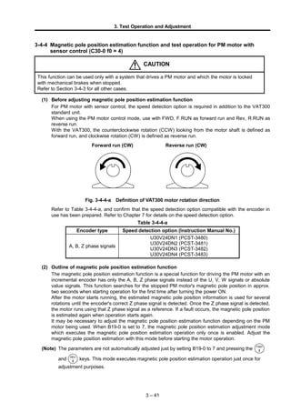
  • 1. 3. Test Operation and Adjustment 3-4-4 Magnetic pole position estimation function and test operation for PM motor with sensor control (C30-0 f0 = 4) CAUTION This function can be used only with a system that drives a PM motor and which the motor is locked with mechanical brakes when stopped. Refer to Section 3-4-3 for all other cases. (1) Before adjusting magnetic pole position estimation function For PM motor with sensor control, the speed detection option is required in addition to the VAT300 standard unit. When using the PM motor control mode, use with FWD, F.RUN as forward run and Rev, R.RUN as reverse run. With the VAT300, the counterclockwise rotation (CCW) looking from the motor shaft is defined as forward run, and clockwise rotation (CW) is defined as reverse run. Forward run (CW) Reverse run (CW) Fig. 3-4-4-a Definition of VAT300 motor rotation direction Refer to Table 3-4-4-a, and confirm that the speed detection option compatible with the encoder in use has been prepared. Refer to Chapter 7 for details on the speed detection option. Table 3-4-4-a Encoder type Speed detection option (Instruction Manual No.) A, B, Z phase signals U30V24DN1 (PCST-3480) U30V24DN2 (PCST-3481) U30V24DN3 (PCST-3482) U30V24DN4 (PCST-3483) (2) Outline of magnetic pole position estimation function The magnetic pole position estimation function is a special function for driving the PM motor with an incremental encoder has only the A, B, Z phase signals instead of the U, V, W signals or absolute value signals. This function searches for the stopped PM motor's magnetic pole position in approx. two seconds when starting operation for the first time after turning the power ON. After the motor starts running, the estimated magnetic pole position information is used for several rotations until the encoder's correct Z phase signal is detected. Once the Z phase signal is detected, the motor runs using that Z phase signal as a reference. If a fault occurs, the magnetic pole position is estimated again when operation starts again. It may be necessary to adjust the magnetic pole position estimation function depending on the PM motor being used. When B19-0 is set to 7, the magnetic pole position estimation adjustment mode which executes the magnetic pole position estimation operation only once is enabled. Adjust the magnetic pole position estimation with this mode before starting the motor operation. (Note) The parameters are not automatically adjusted just by setting B19-0 to 7 and pressing the and keys. This mode executes magnetic pole position estimation operation just once for adjustment purposes. 3 – 41
  • 2. 3. Test Operation and Adjustment CAUTION Precautions for executing magnetic pole position estimation adjustment mode (PM motor control) β€’ Do not carry out maintenance, such as wiring or mounting the option PCB while the PM motor is running. Even if the inverter power is not turned ON, the PM motor could rotate by the connected load or machine and cause a high voltage to be generated in the motor terminals. If the PM motor is connected to the inverter, the inverter could be powered when the PM motor rotates. Confirm that the PM motor is fixed with brakes before starting wiring work, etc. β€’ Before mounting the PCB for the speed detection option onto the control PCB, always turn the inverter power OFF and wait at least 10 minutes. Confirm that all displays on the operation panel are OFF and that the "CHARGE" LED in the unit is OFF before starting the mounting work. Note that the main circuit terminals are charged to a high voltage. β€’ Always ground the motor and inverter. β€’ Always confirm the safety around the motor before starting the magnetic pole position estimation adjustment. β€’ The magnetic pole position estimation adjustment mode can be executed only in the local operation mode. Confirm that the "LCL" LED on the operation panel is ON. β€’ If magnetic pole position estimation operation does not end properly, always turn the inverter power OFF before investigating and confirming the state. β€’ The contact output FLT will activate if magnetic pole position estimation ends abnormally. In equipment that uses this contact, keep the operation of the related devices in mind. β€’ After setting the parameters or after adjusting the magnetic pole position estimation, do not move the position at which the encoder is fixed onto the motor, or interchange the motor's U, V, W phase wires. 3 – 42
  • 3. 3. Test Operation and Adjustment (3) Adjusting magnetic pole position estimation function Carry out automatic tuning with the following procedures. Refer to Chapter 4 for details on using the operation panel. (1) Preparation (2) Turn power ON, start VAT300 (3) Selecting the control mode (Set C30-0) (4) Initialization of motor ratings and constants (5)Setting the ASR and ACR parameters (6) Setting the encoder parameters (7) Adjusting the magnetic pole position estimation function End of adjustment Procedures for adjusting the magnetic pole position estimation function Fig. 3-4-4-b Procedures for adjusting magnetic pole position estimation function for PM motor control 1) Preparation (Before turning the power ON) Confirm that the motor is locked with mechanical brakes. Confirm at the speed detection option PCB is correctly mounted on the control PCB, and that the encoder signal wire is correctly connected to the speed detection option. Refer to the instruction manual of the speed detection option being used for details on connecting the encoder signal wire. 2) Turning the power ON and starting VAT300 Turn the power ON. (In the case of U30V24OP1) After carrying out an initial check of the operation panel for approx. 5 seconds, the display changes as shown on the right. The "LCL" LED also turns ON. (In the case of U30V24OP2) All LEDs on the numeric display will turn ON for a short time, and then " ", " " and " " will appear. The "LCL" and "Hz" LEDs will also turn ON. (Note) When the power is turned ON next (after setting C30-0 f0 = 4), "D00-2" will appear on the display, and the "Hz" LED will not light. This is because the mode is set to the PM motor vector control mode. 3 – 43 Hz A οΌ… LCLFWD REV FLT Out put f r e que nc y D00- 0 OFF. Hz FWD REV FLT LCL
  • 4. 3. Test Operation and Adjustment 3) Selecting the control mode β€’ Set A05-2 to 1. (Set the hardware option function display ON.) β€’ Set the control mode selection: C30-0 f1 f0. This parameter must be set first. PM motor with sensor control mode is to be used, so set C30-0 f0 = 4. Set c30-0 f1 f0 as shown below according to the load. Normal overload setting: C30-0 f1 f0 = 1 4 Heavy overload setting : C30-0 f1 f0 = 2 4 (Note 1) The default value is set to V/f control and normal overload setting (C30-0=11), so always change C30-0. (Note 2) If the fault "SP-5" occurs when the C30-0 setting is changed, the following causes can be considered. β€’ The speed detection option is not mounted correctly. β€’ The encoder signal wire is not connected correctly, or is broken Turn the inverter power OFF and check the state. 4) Initialization of motor rating and motor constants Input the parameters required for PM motor control. Set the parameters shown in Table 3-4-4-b. Table 3-4-4-b Parameter No. Name B01-0 B01-1 B01-2 B01-3 B01-4 B01-5 B01-6 B01-7 B01-8 Rated input voltage setting [No.] Motor rated output [kW] No. of motor poles [Pole] Rated output voltage [V] Max. speed [minβˆ’1 ] Base speed [minβˆ’1 ] Motor rated current [A] Carrier frequency No. of encoder pulses [P/R] B03-0 B03-1 B03-2 B03-3 B03-4 R1: PM motor primary resistance (Mantissa section) [mΩ] R1: PM motor primary resistance (Exponent section) Ld: PM motor d axis inductance (Mantissa section) [mH] Lq: PM motor q axis inductance (Mantissa section) [mH] Ld, Lq: PM motor inductance (Exponent section) * The max. speed cannot be set below the base speed, and the base speed cannot be set above the max. speed. 5) Setting the ASR and ACR parameters Do not change the ASR (speed control) and ACR (current control) parameters shown in Table 3- 4-4-c from the default values before adjusting the magnetic pole position. Note that A10-1 must be set to the value obtained with the following expression. Table 3-4-4-c Parameter No. Name Standard value A10-0 A10-1 A10-2 A10-3 A10-4 ASR response Machine time constant Integral time constant compensation coefficient ASR drive torque limiter ASR regenerative torque limiter 10.0 [rad/s] 1000 [s] 100 [%] 100 [%] 100 [%] A20-0 A20-1 ACR response ACR time constant 1500 [rad/s] 10.0 [ms] 3 – 44
  • 5. 3. Test Operation and Adjustment Refer to the following expression, and set the A10-1: machine time constant setting to match the inertia of the entire load connected with the PM motor. The machine time constant (Tm) refers to the time required to accelerate to the base rotation speed from the zero speed at the rated torque. Tm [ms] = 10.97 Γ— J [kgβ€’m2 ] Γ— (Nbase [min-1 ])2 / Power [W] J : Total inertia [kgβ€’m2 ] ( = 1/4 Γ— GD2 [kgfβ€’m2 ]) Nbase : Base rotation speed [min-1 ] Power : Motor rated output [W] 6) Setting the encoder parameters The encoder parameters shown in Table 3-4-4-d must be set. Table 3-4-4-d Parameter No. Name C50-2 Encoder AB advance direction selection C50-3 Encoder ABZ pulse type selection C51-0 Encoder selection C51-1 AB phase-Z phase type selection C51-2 Encoder Z signal reversal C51-4 Z-IN β†’ U phase winding phase angle The method for setting each parameter is shown below. Set these in order. [1] C51-0: Encoder selection Use the default value when using the magnetic pole position estimation function. [2] C50-2: Encoder AB advance direction selection With the VAT300, the rotation in the counterclockwise direction (CCW) looking from the motor shaft is defined as forward run, and in the clockwise direction (CW) is defined as reverse run. Determine this parameter’s setting value according to the phase relation of the encoder AB phase signals during forward run. A phase B phase (a) When C50-2=1 A phase B phase (b) When C50-2=2 Time Time Fig. 3-4-2-c Encoder AB advance direction selection (Note) If C50-2 is set to 2, set C50-3 to 0. [3] C51-1 : AB phase-Z phase type selection [4] C51-2 : Encoder Z signal reversal With the VAT300, the four patterns shown in Fig.-3-4-3-c are estimated for the A, B and Z phase pulse encoder signals. C51-1 is set based on the phase relation of the A phase signal's rising edge and the Z phase signal. With this setting and at a time of reverse running, the A phase signal's down edge during the Z phase being high is the zero point. To generate the A phase signal rising edge when the Z phase signal is High (Fig. (a)), set C51-1 to 0. In this case, the A phase signal rising edge will be the zero point (magnetic pole position). In all other cases, set C51-1 to 1. In this case, the Z phase signal's rising edge will be the zero point. (Fig. (b)). In this case, the Z phase rising edge is the zero point even at a time of the reverse running. If the Z phase signal needs to be reversed to match the following signal definition, set C51-2 to 1. 3 – 45
  • 6. 3. Test Operation and Adjustment Zero point A phase B phase (a) When C51-1=0 (during CCW rotation) A phase B phase (b) When C51-1=1 (during CCW rotation) Time Time Zero point Z phase Z phase Zero point A phase B phase (c) When C51-1=0 (during CW rotation) A phase B phase (d) When C51-1=1 (during CW rotation) Time Time Zero point Z phase Z phase Fig. 3-4-4-d A, B and Z phase pulse encoder signals (Note) If C51-2 is set to 1, set C50-3 to 0. [5] C50-3 : Encoder ABZ pulse type selection Only when using an encoder with signal specifications that cannot be handled with the C50-2 and C51-2 settings, set C50-3 to reverse or interchange the signals. The signal conversion circuit will function with the combination shown in the table below according to the C50-3 setting value. (Note) Set C50-3 to 0 (no signal reversal/interchange) when C5-2 and C51-2 have been set. C50-3 setting value A-IN forward/ reverse run B-IN forward/ reverse run Z-IN forward/ reverse run AB inter- change 0 – – – No inter- change 1 Reverse – – 2 – Reverse – 3 Reverse Reverse – 4 – – Reverse 5 Reverse – Reverse 6 – Reverse Reverse 7 Reverse Reverse Reverse 8 – – – AB inter- change 9 Reverse – – 10 – Reverse – 11 Reverse Reverse – 12 – – Reverse 13 Reverse – Reverse 14 – Reverse Reverse 15 Reverse Reverse Reverse [6] C51-4: Z-IN β†’ U phase winding phase angle This can be automatically adjusted with automatic tuning when the motor can be run in an isolated state without a load connection. Release the external brakes, and refer to Section 3-5-3 and carry out step 7 and following of the Fig. 3-4-3-c flow chart. In other cases, this parameter is adjusted after the magnetic pole position estimation function has been adjusted. Proceed to adjustment of the magnetic pole position estimation. 3 – 46 Fig. 3-4-4-e Signal conversion circuit AB interchange Reverse A- IN1 B- IN1 Z- IN A phase signal B phase signal Z phase signal
  • 7. 3. Test Operation and Adjustment 7) Adjusting the magnetic pole position estimation function The magnetic pole position estimation function is adjusted. [1] Select the magnetic pole position estimation mode with the magnetic pole position estimation selection (B39-0 f0). When the magnetic pole position estimation function is used, normally f0 = 2 should be selected. If the motor has a reverse inductance (Ld<Lq), select f0 = 3. (Refer to Section 6-9 for an explanation on the PM motor circuit constant.) Select f0 = 3, when not using a magnetic pole position estimation function, or when you stop use. [2] When B19-0 is set to 7 and the LCL SET key is pressed, the magnetic pole position estimation mode which executes the magnetic pole position estimation operation once will start. To carry out the same operation again, repeat the above step. When the magnetic pole position estimation function starts normally, the operation will end in approx. two seconds. (Note) The parameters are not automatically adjusted just by setting B19-0 to 7 and pressing the and keys. This mode executes magnetic pole position estimation operation just once for adjustment purposes. [3] Adjust the magnetic pole position estimation function The parameters required for adjusting the magnetic pole position estimation function are shown in Table 3-4-4-e. The parameters which indicate the magnetic pole position estimation results are shown in Table 3-4-4-f. Table 3-4-4-e Parameter No. Name B39-1 Magnetic pole position estimation voltage B39-2 Magnetic pole position estimation time B39-3 Voltage error correction current A20-0 ACR response (PM motor control) A20-1 ACR time constant (PM motor control) Table 3-4-4-f Parameter No. Name Adjustment reference D16-0 Characteristic amount during magnetic pole position estimation 1 Adjust to 120% or more. D16-1 Characteristic amount during magnetic pole position estimation 2 Adjust to 120% or more. D16-2 Magnetic pole position estimation current Make sure the current does not exceed 120%. If too high, the inverter could stop with an overcurrent (OCT) fault. D16-3 Magnetic pole position estimation error Adjust to within 10Β°. If B39-1, 2 (magnetic pole position estimation voltage) is increased, D16-0, 1 will increase. Adjust to match the adjustment reference conditions given in Table 3-4-4-f. When D16-0, 1 is at the adjustment reference value, normally, the D16-3 value will be within the adjustment reference range. If B39-1, 2 is too large, the noise during estimation will increase. If the generated noise is too large, decrease D39-1, 2 within the range that the adjustment reference given in Table 3-4-4-f is satisfied. To decrease B39-1, 2, first decrease B39-1. If the noise is still large even after B39-1 is decreased by 20%, then decrease B39-2. 3 – 47
  • 8. 3. Test Operation and Adjustment If D16-0 to 3 do not stabilize even after carrying out the magnetic pole position estimation operation repeatedly, it might stabilize by increasing B39-3 by approx. 20%. However, normally B39-3 can be set to the default value without problem. If the magnetic pole position estimation function operation takes more than two seconds, ACR must be adjusted. Increase A20-0 (ACR response) or decrease A20-1 (ACR time constant) so that the magnetic pole position estimation operation ends in approx. two seconds. If the magnetic pole position estimation results are not stable for any reason, the magnetic pole position estimation function cannot be used. Use an encoder with a magnetic pole position detection signal, such as a UVW signal or serial absolute signal. Refer to Section 3-5-3, set the encoder, and carry out test operation. [4] When finished adjusting the magnetic pole position estimation function, return the setting to B19-0=0. (Note 1) When the magnetic pole position estimation adjustment mode is carried out with B19- 0 set to 7, the SFP (magnetic pole position established) flag is set so the magnetic pole position will not be estimated the next item operation is set. B19-0 must be returned to 0. (Note 2) After setting these parameters, do not move the encoder fixed onto the motor, or interchange the motor's U, V, W phase wires. 3 – 48
  • 9. 3. Test Operation and Adjustment (4) Setting the parameters for the external brake function, etc. 1) Setting the external brake control function The external brakes can be turned ON and OFF following the inverter's internal sequence. The external brake function has various wait time settings and interlock functions. This function is set. The parameters which need to be set are shown in Table 3-4-4-g. Table 3-4-4-g Parameter No. Name B46-0 External brake selection B46-1 Brake open wait time (LB) B46-2 Acceleration start wait time (BL) B46-3 Brake close wait time (DB) B46-4 RUN error judgment time at brake closed B46-5 Brake answer error judgment time [1] B46-0: External brake selection Set B46-0 f0 to 2 to use the external brake control function. When B46-0 f1 is set to 2, the interlock function using IDET is enabled. If IDET does not turn ON when the brakes are released (immediately after LB), the motor will stop with a fault "IO-C". Set the control mode for the acceleration wait time (LB, BL) with B46-0 f2. When f2 is set to 1, the normal operation mode is enabled. When f2 is set to 2, the DC brake mode is enabled. [2] B46-1: Brake open wait time (LB) Set the time to wait (LB) from RUN to brake open. [3] B46-2: Acceleration start wait time (BL) Set the wait time (LB) from brake open to start of acceleration. If brake answer is enabled (B46-5β‰ 0.0sec) set the time after brake answer. If brake answer is disabled (B46-5=0), set the time from the brake open command. When using normal operation mode setting, the program settings will not be changed during BL, and instead the settings prior to BL will be held. [4] B46-3: Brake close wait time (DB) Set the wait time (DB) from time from ZSP (zero speed) ON to brake close. [5] B46-4: RUN error judgment time at brake closed If RUN does not turn OFF at the time set in D46-4 after the brakes are closed, the host controller will judge that there is an error, and will stop the motor with the external brake RUN error (IO-D) fault. RUN error judgment can be turned OFF by setting 0.0sec. [6] B46-5: Brake answer error judgment time If brake command (MBRK) and brake answer (MBRK_ans) do not match for longer than the time set in B46-5, it will be judged as an external brake fault, and the motor will stop with the external brake answer error (IO-E) fault. Brake answer error judgment can be turned OFF by setting 0.0sec. 3 – 49
  • 10. 3. Test Operation and Adjustment An example of the external brake sequence is shown below. RUN Program setting input Internal program setting 0 0 7 7 3 3 0 0 External brake command (MBRK) B46-1 (LB) B46-2 (BL) B46-3 (DB) ZSP Not changed B46-4 Run error judgment External brake answer (MBRK_ans) Output frequency/ motor speed command (a) Example of external brake sequence when using program settings (B46-0 f2=1) and with brake answer (B46-5β‰ 0.0) RUN External brake command (MBRK) B46-1 (LB) B46-2 (BL) B46-3 (DB) ZSP B46-4 Run error judgment DC brake ON OFF ON Normal DC brake time ON Output frequency/ motor speed command (b) Example of external brake sequence when using DC brake (B46-0 f2=2) and no brake answer (B46-5=0.0.) Fig. 3-4-4-f Example of external brake sequence External brake control (B46) is sequenced with magnetic pole position estimation function. The external brake control starts after the magnetic pole position estimation is completed. Thus, the magnetic pole position estimation time does not need to be considered for the external brake function. 2) Setting the external brake control sequence [1] The J1 setting must be turned ON to use external brake control or the other sequence functions. Set C00-5 to 2. [2] Set the external brake signal (MBRK) sequence output function. Refer to the following table, and set "27" for the parameter corresponding to the output terminal being used. Set "-27" to reverse the signal. Control PCB output terminal Corresponding parameter RC-RA C13-2 PS01 C13-3 PS02 C13-4 PS03 C13-5 FA-FC C13-6 3 – 50
  • 11. 3. Test Operation and Adjustment [3] Set the external rake answer signal (MBRK_ans) sequence input function. Refer to the following table and set the value corresponding to the input terminal (control PCB PSI1 to 11) in C04-E. Set a negative value to reverse the signal. Control PCB input terminal C04-E setting value (Note 2) PSI1 1 PSI2 2 PSI3 3 PSI4 4 PSI5 5 PSI6 6 PSI7 7 PSI8 (Note 1) 8 PSI9 (Note 1) 9 PSI10 (Note 1) 10 PSI11 (Note 1) 11 (Note 1) PSI8 to 11 are the relay option PCB's sequence input terminals. Prepare the relay option to use these. (Note 2) Do not set C04-E to "0" or "16". The MBRK_ans signal input will be fixed to OFF or fixed to ON. 3) Setting the ACR reverse run prevention function If the motor must not rotate in the reverse direction of the run command, set the reverse run detection error level in C24-7. If the motor rotates in the reverse direction, it will stop with a fault. Set this parameter as a percentage of the error detection level speed using the base speed as 100%. This function is invalid when "0" is set. (5) Setting the C51-4: Z-IN β†’ U phase winding phase angle parameter In the PM motor control mode, the C51-4: Encoder Z-IN β†’ U phase winding phase angle parameter must be set. Set this parameter. If the settings up to this point have not been completed, refer to the previous section and complete the settings. (Note) This can be automatically adjusted with automatic tuning when the motor can be run in an isolated state. Release the external brakes, and refer to Section 3-4-3 and carry out step 7 and following of the Fig. 3-4-3 flow chart. This step can be skipped if the parameter is set with automatic tuning. This parameter must be set only once at the very start of operation. After setting this parameter, do not move the encoder fixed onto the motor, or interchange the motor's U, V, W phase wires. 1) The motor must be rotated to set this parameter. First, set the speed and ramp time parameters required for rotating the motor. Refer to Table 3- 4-4-h and set each parameter. Table 3-4-4-h Parameter No. Name Setting method A00-2 Direct setting speed Set the motor speed with a [min-1 ] unit. A01-0 Acceleration ramp time Set the acceleration time from stop to maximum speed, and the deceleration time from maximum speed to stop. A01-1 Deceleration ramp time 3 – 51
  • 12. 3. Test Operation and Adjustment CAUTION The motor will rotate with the next step. Confirm the safety around the motor before starting the next step. 2) When issuing the run/stop commands from the operation panel (local operation mode), confirm that "LCL" is ON. When using sequence input (remote operation mode), confirm that "LCL" on the operation panel is OFF. Press the LCL SET + STOP keys to change the operation mode. 3) Set B39-0 f1 to 2. With this setting, the encoder's Z phase is not used, and the motor is run with the estimated magnetic pole phase. Start and stop in this mode. 4) Set the speed with the operation panel. Set the speed setting input point selection C02-0 to 3 (panel fixed). Set the motor speed in A00-2. 5) Open the external brakes to rotate the motor. 6) Input the forward run command. To issue the command from the operation panel, press the key. 7) Input the stop command, and stop the motor. To issue the command from the operation panel, press the STOP key. 8) After stopping, set the value displayed at D26-0 in C51-4. 9) Set B39-0 f1 to 1. The mode will return to the normal operation mode. (6) Test operation When finished with automatic tuning, test run the isolated motor, and make sure that there are no errors. Use the following procedures to test the operation with the operation panel. Refer to Chapter 4 for details on using the operation panel. When issuing the run/stop commands from the operation panel (local operation mode), confirm that "LCL" is ON. When using sequence input (remote operation mode), confirm that "LCL" on the operation panel is OFF. Press the LCL SET + STOP keys to change the operation mode. 1) Set the speed from the operation panel. Set speed setting input point selection: C02-0= 3 (panel fixed). Set the motor speed in A00-2. CAUTION The motor will run. Confirm the safety around the motor before starting the next step. 2) Open the external brakes to rotate the motor. 3) Press the RST MOD key to display the D00-2 on the monitor, and then input the forward run command To issue the command from the operation panel, press the key. The "FWD" lamp will turn ON, and the display will start increasing from " ". Confirm the speed with D00-2, and make sure that it is equal to the A00-2 setting value. 3 – 52
  • 13. 3. Test Operation and Adjustment CHECK 1. Did the motor run? 2. Is the run direction correct? Check the wiring and operation if abnormal. 3. Is the rotation smooth? 4) Input a reverse run command and confirm that the motor runs in reverse. To issue the command from the operation panel, press the key. 5) Input the stop command, and stop the motor. To issue the command from the operation panel, press the STOP key. The operations for changing the speed during motor rotation are started next. 6) Input the forward run command. To issue the command from the operation panel, press the key. 7) Press the RST MOD key several times. Set so that " " and the current speed setting value appear alternately on the display (with the U30V24OP1, the 2 section of "A00-2: current speed setting value min-1 " will flicker). 8) Press the LCL SET key once. The display will stop at the current setting value, and the first decimal digit will flicker. This completes preparation for changing the motor speed. The digit to be changed can be moved with the key. The speed can be increased or lowered with the keys ( knobs with U30V24OP1). 9) Change the A00-2 setting value and press the LCL SET key. Display D00-2 and confirm that the motor speed has changed to the set value. (Note) The operation panel frequency change operation is set to be changed (C11-2=1) in real time at the factory shipment settings, and therefore the output frequency is changed in real time using the keys ( knobs with U30V24OP1), without having to press the LCL SET key. When the LCL SET key is pressed, the current setting value will be saved. CAUTION A 10-second acceleration and 20-second deceleration ramp time are set as defaults. The motor will slowly increase its speed to the set value. (When the set value is not changed) Change the A00-2 setting value with an interval of 10% or less of the maximum speed. (Use the keys or knobs with U30V24OP1.) 3 – 53
  • 14. 3. Test Operation and Adjustment 10) Confirm that the motor speed (D00-2 display) is the same as the setting value, and then input the stop command. Press the STOP key when using the operation panel. The display will decrease to "0.0" in several seconds. The "FWD" or "REV" LED will flicker for two seconds while the DC-brake is applied and the motor will stop. This completes the test operation. (Note) When the test operation ends, the parameter A10-1: machine time constant setting matches the motor unit's inertia. Refer to Section 6-8 and reset this parameter to match the inertia of the user's machine. (7) Other functions of magnetic pole position estimation 1) Magnetic pole position estimation retry function If the characteristics amount measured during magnetic pole position estimation do not reach the reference value, the magnetic pole position estimation will be retried. The retry conditions are shown in Table 3-4-4-i. The estimation is retried up to three times. If the reference is not reached after three retries, the operation will stop with a fault (ATT-9). If this fault occurs, adjust the magnetic pole position estimation function again. Table 3-4-4-i Parameter No. Name Adjustment reference D16-0 Characteristic amount during magnetic pole position estimation 1 110% or less D16-1 Characteristic amount during magnetic pole position estimation 2 110% or less D16-3 Magnetic pole position estimation error 20Β° or more 2) Sequence output The magnetic pole position setting flag can be sequence output. If C13-2 to 6 is set to 40 (FPOS), when the magnetic pole position is set the output will turn ON from the control PCB terminal corresponding to each parameter. If C13-2 to 6 is set to -40, a signal with the sequence logic reversed will be output. Whether to output the sequence output RUN signal during the magnetic pole position estimation period can be selected with parameter B39-0 f3. (ON when 1 is set, OFF when 2 is set.) (LB) (BL) ZSP (DB) Once FPOS is set, it does not turn OFF unless there is a fault しγͺγ„ι™γ‚Š OFF しγͺい Magnetic pole position estimation period RUN command RUN answer (RUN) Magnetic pole position setting (FPOS) Brake command (MBRK) Brake answer (MBRK_ans) Fig. 3-4-4-g Sequence outputs related to magnetic pole position estimation (8) Other settings and adjustments This completes the adjustment of the magnetic pole position estimation function, setting of the external brake control function, and test operation. Refer to Chapter 4 and set or adjust the sequence, etc., to match the user's application. Refer to Section 6-9 for details on adjusting the PM motor vector control system parameters. 3 – 54
  • 15. 3. Test Operation and Adjustment 3-4-5 Automatic tuning error messages If automatic tuning ends abnormally, the following message will appear. Investigate and confirm the state following the error code. E00:ATT-n (for U30V24OP1), (for U30V24OP2) n: Automatic tuning step No. Cause and remedy n=1 The motor may not be connected correctly. Check the connection. The B00 and B01 parameters may not be set correctly. Check the parameter setting. The motor with the special circuit constants may be applied. Change B19-1and B19-2 parameters. n=2 The B00 and B01 parameters may not be set correctly. Check the parameter setting. n=3 The load and machine may not be separated. Separate the load and machine. Lengthen the acceleration time (A01-0). Lengthen the deceleration time (A01-1). If the motor vibrates, adjust the torque stabilizing gain (B18-2). n=4 The load and machine may not be separated. Separate the load and machine. If the motor vibrates, increase the torque stabilizing gain (B18-2). n=5 When the motor does not stop Increase the acceleration/deceleration time (A01-0, A01-1). When the motor does stop The B00 and B01 parameters may not be set correctly. Check the parameter setting. n=6 The B00 and B01 parameters may not be set correctly. Check the parameter setting. n=8 Indicates that the output voltage did not stabilize for 1 second or more during magnetic pole position estimation for the PM motor. Adjust the magnetic pole position estimation voltage (B39-1) and magnetic pole estimation time (B39-2). n=9 Indicates that the PM motor magnetic pole estimation did not end normally even after retrying three times. Adjust the magnetic pole position estimation voltage (B39-1) and magnetic pole estimation time (B39-2). 3 – 55