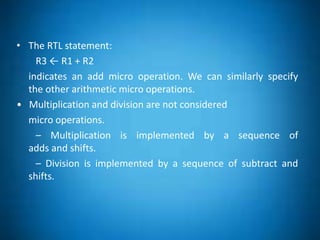
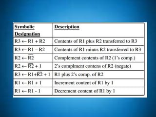
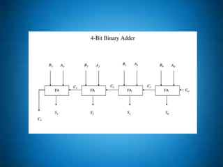
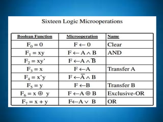
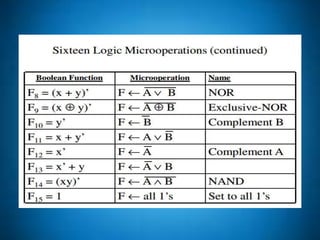
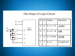
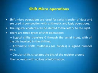
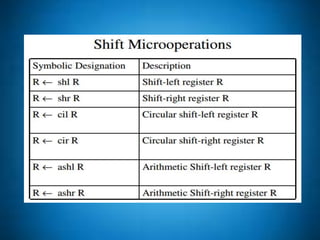
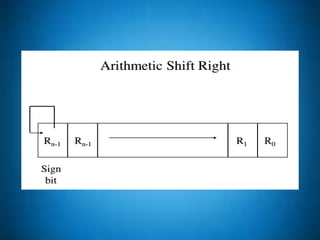
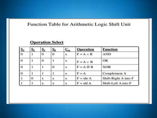
2. MICRO OPERATIONS
• Digital systems are modular in nature, with modules
containing registers, decoders, arithmetic elements, control
logic, etc.
• These digital components are defined by the registers that
they contain and the operations performed on their data.
These operations are called micro operations.
• Micro operations are elementary operations performed on the
information stored in one or more registers.
3. ARITHMETIC MICRO OPERATIONS
• Unlike register transfer micro operations, arithmetic micro
operations change the information content.
• The basic arithmetic micro operations are:
– addition
– subtraction
– increment
– decrement
– shift
4. • The RTL statement:
R3 ← R1 + R2
indicates an add micro operation. We can similarly specify
the other arithmetic micro operations.
• Multiplication and division are not considered
micro operations.
– Multiplication is implemented by a sequence of
adds and shifts.
– Division is implemented by a sequence of subtract and
shifts.
5.
6. Binary Adder
• We implement a binary adder with registers to hold the data and
a digital circuit to perform the addition (called a binary adder).
• The binary adders is constructed using full adders connected in
cascade so that the carry produced by one full adder becomes an
input for the next.
• Adding two n-bit numbers requires n full adders.
• The n data bits for A and B might come from R1and R2 respectively
7.
8. Adder-Subtracter
• Subtracting A – B is most easily done by adding B’ to A and
then adding 1.
• This makes it convenient to combine both addition and
subtraction into one circuit, called an adder subtracter .
• M is the mode indicator
– M = 0 indicates addition (B is left alone and C0is 0)
– M = 1 indicates subtraction (B is complement and C0 is 1).
9.
10. BINARY INCREMENTER
• The binary incrementer adds 1 to the contents of a register,
e.g., a register storing 0101 would have 0110 in it after being
incremented.
• There are times when we want incrementing done
independent of a register. We can accomplish this with a
series of cascading half-adders.
11.
12. Logic Micro operations
• Logic micro operations are binary operations performed on
corresponding bits of two bit strings.
• Example: P: R1 ← R1 ⊕ R2
1010 Content of R1
1100 Content of R2
0110 Content of R1 after P = 1
• Special Symbols used for logic operations:
∧ - AND ∨ - OR ⊕ - XOR
This avoids confusing AND with multiplication, OR with
addition, etc.
13.
14.
15.
16. Logic Applications
• Logic Operations allow us to manipulate individual bits in
ways that we could not do otherwise.
• These applications include:
– selective set
– selective complement
– select clear
– mask
– insert
– clear
17. Shift Micro operations
• Shift micro operations are used for serial transfer of data and
are used in conjunction with arithmetic and logic operations.
• The register contents can be shifted to the left or to the right.
• There are three types of shift operations:
– Logical shifts transfers 0 through the serial input, with all
the bits involved in the shifting.
– Arithmetic shifts multiplies (or divides) a signed number
by 2.
– Circular shifts circulates the bits of the register around
the two ends with no loss of information.
18.
19.
20. Arithmetic Logic Shift Unit
Instead of having individual registers performing the various
micro operations, computers use an Arithmetic Logic Unit
which combine these functions