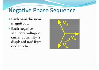
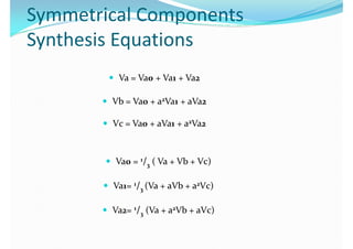
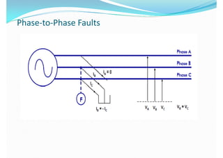
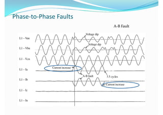
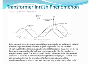
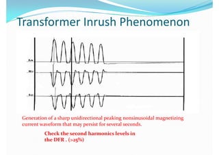
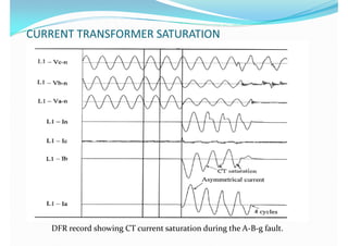
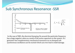
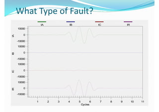
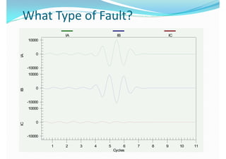
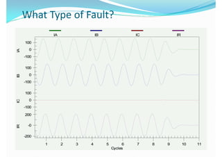
www.elecsolution.com























































Karikalan.MKarikalan.M
1)1)1)
2)2)
3)3)
4)4)





 2 2
 2 2
 1 1
3 3
1 2 1
3
2 3
 1
3
2 1
3
2





9090
I2
45135
I2
45135
0180
V1V2
0180
V1
225 315
I1I1
270270
C Phase Symmetrical Component View of an A to B Phase FaultC Phase Symmetrical Component View of an A to B Phase Fault
9090
45135 45135
V0 V1V2
0180 V0 V1V2
225 315225 315
I0I1 I0I1
I2
270
I2
270











9090
45135 45135
I2I2
I0I0
V1 0180 V0
V1
V2 V0V2
225 315225 315
I1I1
270






IA IB IC IRIA IB IC IR
100
0
100
0
-100-100
100100
0
-100-100
100100
0
-100
0
-100
200200
-0-0
-200-200
1 2 3 4 5 6 7 8 9 10 111 2 3 4 5 6 7 8 9 10 11
Cycles
90
45135 45135
V2
I1
V2
0180 I0
I1
I2 0180 I0 I2
V1V1
225 315225 315
270270
 Fault incident on voltage Fault incident on voltage
zero point results inzero point results in
Asymmetrical current waveAsymmetrical current wave
Karikalan.MKarikalan.M





Dead time -1 secDead time -1 sec


Karikalan.MKarikalan.M







In inductive circuits the current normally lags the voltage by 90, and magnetic flux isIn inductive circuits the current normally lags the voltage by 90, and magnetic flux is
normally in phase with the inductive magnetizing current that has created it.normally in phase with the inductive magnetizing current that has created it.
Therefore, at the transformer energization instant the required magnetic flux shouldTherefore, at the transformer energization instant the required magnetic flux should
be at 90, to correspond to the high-side zero-voltage point. But the transformerbe at 90, to correspond to the high-side zero-voltage point. But the transformer
magnetic circuit has no flux, and as a result the flux must start at the zero point andmagnetic circuit has no flux, and as a result the flux must start at the zero point andmagnetic circuit has no flux, and as a result the flux must start at the zero point and
overshoot to twice the maximum value during the first voltage cycle. This will causeovershoot to twice the maximum value during the first voltage cycle. This will cause
core saturation, forcing the generation of a sharp unidirectional peakingcore saturation, forcing the generation of a sharp unidirectional peaking
nonsinusoidal magnetizing current waveform that may persist for several seconds.nonsinusoidal magnetizing current waveform that may persist for several seconds.







L HL H



Microsoft OfficeMicrosoft Office
Word 97 - 2003 DocumentWord 97 - 2003 Document
Karikalan.MKarikalan.M
VA VB VC IA IB IC
25
VA VB VC IA IB IC
0
25
-25
0
-25
25
0
25
-25
0
-25
25
0
25
-25
2500
0
2500
0
-2500
2500
0
-2500
0
-2500
2500
0
2500
0
-2500-2500
1 2 3 4 5 6 7 8 9 10 111 2 3 4 5 6 7 8 9 10 11
Cycles
IA IB IC IRIA IB IC IR
10000
00
-10000-10000
1000010000
0
-10000-10000
1000010000
00
-10000-10000
1000010000
00
-10000-10000
1 2 3 4 5 6 7 8 9 10 111 2 3 4 5 6 7 8 9 10 11
CyclesCycles
IA IB IC
10000
IA IB IC
10000
00
-10000-10000
1000010000
00
-10000-10000
10000
00
-10000-10000
1 2 3 4 5 6 7 8 9 10 111 2 3 4 5 6 7 8 9 10 11
CyclesCycles
IA IB IC IR
5000
IA IB IC IR
5000
00
-5000
50005000
00
-5000-5000
50005000
00
-5000-5000
25002500
00
-2500-2500
1 2 3 4 5 6 7 8 9 10 111 2 3 4 5 6 7 8 9 10 11
CyclesCycles
IA IB IC IRIA IB IC IR
100
0
100
0
-100-100
100100
0
-100
0
-100
100
00
-100
200200
-0-0
-200-200
1 2 3 4 5 6 7 8 9 10 111 2 3 4 5 6 7 8 9 10 11
CyclesCycles
KARIKALAN.M

Power system fault analysis ppt