IRJET - Surface Wear Analysis of Spur Gear
•
0 likes•22 views

https://www.irjet.net/archives/V7/i3/IRJET-V7I3644.pdf

Recommended
Recommended
More Related Content
What's hot
What's hot (20)
Similar to IRJET - Surface Wear Analysis of Spur Gear
Similar to IRJET - Surface Wear Analysis of Spur Gear (20)
More from IRJET Journal
More from IRJET Journal (20)
Recently uploaded
Recently uploaded (20)
IRJET - Surface Wear Analysis of Spur Gear
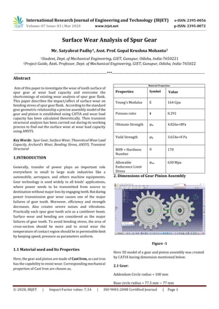
- 1. International Research Journal of Engineering and Technology (IRJET) e-ISSN: 2395-0056 Volume: 07 Issue: 03 | Mar 2020 www.irjet.net p-ISSN: 2395-0072 © 2020, IRJET | Impact Factor value: 7.34 | ISO 9001:2008 Certified Journal | Page 1 Surface Wear Analysis of Spur Gear Mr. Satyabrat Padhy1, Asst. Prof. Gopal Krushna Mohanta2 1Student, Dept. of Mechanical Engineering, GIET, Gunupur, Odisha, India-7650221 2Project Guide, Asst. Professor, Dept. of Mechanical Engineering, GIET, Gunupur, Odisha, India-765022 ---------------------------------------------------------------------***--------------------------------------------------------------------- Abstract Aim of this paper to investigate the wear of tooth surface of spur gear at wear load capacity and overcome the shortcomings of existing wear analysis of spur gear flank. This paper describes the impact/affect of surface wear on bending stress of spur gear flank. According to the standard gear geometric relationship a precise assembly model of the gear and pinion is established using CATIA and wear load capacity has been calculated theoretically. Then transient structural analysis has been carried out during its working process to find out the surface wear at wear load capacity using ANSYS. KeyWords: SpurGear, Surface Wear, Theoretical WearLoad Capacity, Archard’s Wear, Bending Stress, ANSYS, Transient Structural 1.INTRODUCTION Generally, transfer of power plays an important role everywhere in small to large scale industries like a automobile, aerospace, and others machine equipments. Gear technology is used widely in all kinds’ applications, where power needs to be transmitted from source to destination without major loss by engaging teeth.Butduring power transmission gear wear causes one of the major failures of gear tooth. Moreover, efficiency and strength decreases. Also creates severe noises and vibrations. Practically each spur gear tooth acts as a cantilever beam. Surface wear and bending are considered as the major failures of gear tooth. To avoid bending stress, the area of cross-section should be more and to avoid wear the temperature of contact region should be in permissiblelimit by keeping speed, pressure as parameters uniform. 1.1 Material used and Its Properties Here, the gear and pinion are made of Cast Iron, ascastiron has the capability to resist wear. Corresponding mechanical properties of Cast Iron are chosen as, Material Properties Properties Symbol Value Young’s Modulus E 164 Gpa Poisons ratio 𝛄 0.291 Ultimate Strength u 4.826e+8Pa Yield Strength y 3.654e+8 Pa BHN = Hardness Number H 170 Allowable Endurance Limit Stress es 630 Mpa 2. Dimensions of Gear Pinion Assembly Figure -1 Here 3D model of a gear and pinion assembly was created by CATIA having dimension mentioned below. 2.1 Gear: Addendum Circle radius = 100 mm Base circle radius = 77.5 mm ~ 77 mm
- 2. International Research Journal of Engineering and Technology (IRJET) e-ISSN: 2395-0056 Volume: 07 Issue: 03 | Mar 2020 www.irjet.net p-ISSN: 2395-0072 © 2020, IRJET | Impact Factor value: 7.34 | ISO 9001:2008 Certified Journal | Page 2 2.2 Pinion: Addendum Circle radius = 85 mm Base circle radius = 62 mm 2.3 Tooth: Face Width = b = 30mm Tooth Thickness = t = 16.31mm Depth = 23 = 18 = 15 α = Pressure Angle 3. Calculation Input Torque = T = 30 N-m Wear Load capacity = Fw = Ks.Qg.Dpp.b Where, Qg = Here, E1 = E2 Ks = Dpp = Pitch Circle diameter of Pinion b = Face width of pinion tooth By putting the corresponding value in above formula, we found, Wear Load Capacity = Fw = 4137.61 N 4. Analysis and Results: To analyze what actually happens during rotation of gears, the 3D model of gear and pinion assembly was imported to ANSYS workbench to perform transient structural analysis. Then theoretical wear load capacity calculated above was applied to the contact region. Here it is noted that wear load capacity is theamount of load applied without premature wear. Figure -2 Figure -3 It was found that during the end of engagement followed by starting of disengagement, the contact surface experience sliding also variation of pressure in that region. The sliding speed and contact pressure is maximum at the end of contact, i.e.: near the flank of tooth. The sliding distance and variation of pressure is shown in fig -2 & 3, respectively. Putting the corresponding values of sliding distance in Archard’swear equation the wear volume at differentpoints near tooth flank along the direction offacewidthis shownin fig 4. Archard’s Wear equation is given by: Q = , Where, Q = Total volume of Wear debris produced K = Wear constant W = Total Normal Load L = Sliding distance H = Hardness
- 3. International Research Journal of Engineering and Technology (IRJET) e-ISSN: 2395-0056 Volume: 07 Issue: 03 | Mar 2020 www.irjet.net p-ISSN: 2395-0072 © 2020, IRJET | Impact Factor value: 7.34 | ISO 9001:2008 Certified Journal | Page 3 0 0.005 0.01 Min. Wear Avg. Wear Max. wear EngagementDirection Wear Volume Near Tooth Flank Wear Volum e Chart -1: Wear Volume in mm3 Also observed that in the same region near flank of tooth stickiness is high, this tries to remove material from contact region. At this region due to high temp and high friction stress as well, there is a chance of removal of the material. Figure -4 Now the above observation can be related to bending stress of a gear tooth. We know that, Bending Stress is given by, As the gears are designed in such a manner that particular tooth of gear does not come incontactwith the sametoothof pinion for next no. of cycles. Hence different tooth surface comes in contact. Gradually thickness of tooth is decreased. So from the bending stress relation, we can easily observe that with the reduction of gear thickness bending stress will be increased. 3. CONCLUSIONS Surface wear is considerably found at tooth flank near root, which increases the value of bending stress relatively high at wear load capacity. Wear atflankcan result higher stress concentration factor due to irregularity. REFERENCES [1] Gear and Gear Unit design By “NPTEL https://onlinecourses.nptel.ac.in/noc20_me18/unit” [2] Machine Design ”https://www.machinedesign.com/learning- resources/engineeringessentials/article/21834512/g ears-look-to-the-future- formaterial#:~:text=Cast%20iron%20is%20a%20co mmon,to%20their%20high%20strength%20values. [3] Reliance Foundry” Byhttps://www.reliance- foundry.com/blog/cast-iron-vs-cast-steel#gref [4] Material Properties” Byhttps://www.jashmetrology.com/difference-in- properties-of-cast-iron-and-mild-steel/” [5] Archard’s Wear and Material Property ” Byhttps://en.wikipedia.org/wiki/Cast_iron and https://en.wikipedia.org/wiki/Archard_equation” [6] AutoDrill ”:http://www.drill- hq.com/2011/11/hardness-scale-for-various- materials/” [7] Fabrice Wavelet ”https://gearsolutions.com/features/ductile-iron-for- open-gearing-a-current-perspective/”