SlideShare a Scribd company logo
1 of 14
Download to read offline
International Research Journal of Engineering and Technology (IRJET) e-ISSN: 2395-0056
Volume: 06 Issue: 02 | Feb 2019 www.irjet.net p-ISSN: 2395-0072
One Day National Conference on Recent Advancement in Civil Engineering (RACE 2K19)
25th February 2019
Organized by
Department of Civil Engineering, T John Institute of Technology, Bangalore-83
© 2019, IRJET | Impact Factor value: 7.211 | ISO 9001:2008 Certified Journal | Page 1922
ANALYSIS AND SYNTHESIS OF EXTRNALLY PLATED REINFORCED
CONCRETE BEAMS
N Sruthi Das
Assistant Professor, T.John Institute of Technology, Bangalore-83
-----------------------------------------------------------------------------***----------------------------------------------------------------------------
ABSTRACT:- Strengthening reinforced concrete (RC) beams by bonding steel or fiber reinforced polymer (FRP) on its
tension face has become a popular retrofit method due to its rapid, simple and other advantages. However, debonding
along the Steel-RC beam interface can lead to premature failure of the structures. Safe design of such a strengthened RC
beam demands a reliable and predictive debonding strength model. This paper presents a careful finite element
investigation into interfacial stresses in the adhesive layer bonding RC beam and soffit plate. Finite element modelling
issues like proper selection of contact between adherents and symmetry conditions are first discussed, with particular
attention on appropriate finite element meshes for the accurate determination of interfacial stresses. The interfacial stress
behaviour at plate end has been analyzed for two cases of loading taken, one by applying uniformly distributed load and
the other with a two point loading. Two special cases are considered in two point loading – for the case when the plate
terminates with-in the constant moment region (CMR) and for the case when plate is extended beyond constant moment
region where bending moment is minimal. The concentration of stresses in the adhesive layer near the plate end
explained the significance in considering their influence in flexural debonding.
Keywords: interfacial stresses, flexural debonding, constant moment region, soffit plate, finite element method.
1. INTRODUCTION
1.1. General
Reinforced concrete structures often have to face modification and improvement of their performance during their
service life. The main contributing factors are change in their use, new design standards, lack of maintenance practices,
deterioration due to corrosion caused by exposure to an aggressive environment and accident events such as earthquakes.
The strengthening of reinforced concrete beams by bonding a soffit plate has become a popular retrofit procedure
.This plate bonding technique has numerous advantages such as increasing the stiffness and strength of an existing
flexural member with minimal impact on the surrounding environment. Considerable research has been undertaken on RC
beams strengthened with a bonded soffit plate. Tests on RC beams bonded with either steel plates or fibre reinforced
plastic plates have revealed that debonding of the soffit plate from the RC beam, typically with the concrete cover attached
to the plate, is a common failure mode in these beams. This debonding failure mode is brittle and prevents the full
utilization of the tensile strength of the bonded plate. It is therefore important to understand the mechanism of this
debonding failure mode and develop sound design rules.
1.2. Bonding agent- adhesive
An adhesive is any substance that, when applied to the surfaces of materials, binds the surfaces together and resists
separation. The use of adhesives offers many advantages over other binding techniques such as sewing, welding, bolting,
screwing, etc.
These advantages include-
 The ability to bind different materials together.
 The ability to distribute stress more efficiently across the joint.
 The cost effectiveness of an easily mechanized process.
International Research Journal of Engineering and Technology (IRJET) e-ISSN: 2395-0056
Volume: 06 Issue: 02 | Feb 2019 www.irjet.net p-ISSN: 2395-0072
One Day National Conference on Recent Advancement in Civil Engineering (RACE 2K19)
25th February 2019
Organized by
Department of Civil Engineering, T John Institute of Technology, Bangalore-83
© 2019, IRJET | Impact Factor value: 7.211 | ISO 9001:2008 Certified Journal | Page 1923
 An improvement in aesthetic design.
 Increased design flexibility.
Disadvantages of adhesive use include- decreased stability at high temperatures, relative weakness in bonding large
objects with a small bonding surface area and greater difficulty in separating objects during testing.
1.3 METHODS AND MATERIALS USED FOR FLEXURAL STRENGTHENING
1.3.1. Using Ferro-cement laminate
Ferro cement is a thin composite material which is composed of cement mortar reinforced with uniformly distributed
layers of continuous, relatively small diameter, wire meshes. Ferro-cement, being of the same cementitious material as
reinforced concrete (RC), is ideally suited as an alternative strengthening component for the rehabilitation of RC
structures. It possesses higher tensile strength to weight ratio and a degree of toughness, ductility, durability and cracking
resistance that is considerably greater than those found in conventional cement based materials. The ferro cement was
utilized for its toughness, cracking resistance and ease of application to fit the difficult contours of structures. For
strengthening beams in flexure pre-fabricated ferro cement reinforcements were attached onto the beams tension face
before the ferro cement matrix was cast to complete the laminate. The beams strengthened without surface roughening
and without using the mechanical shear connectors’ exhibits localized horizontal cracks along the concrete/ferro cement
interface and severe de-lamination of the ferro cement at failure.
1.3.2 Using externally bonded plates
Externally bonded steel plates and polymer composites are more significant materials regarding flexural strengthening
purpose. Primarily steel plates were used for strengthening and repairing of RC members. The use of advanced composite
fibre materials as external flexural reinforcement of concrete and other structures has progressed well in the past decade
in selective applications where cost disadvantage is outweighed by a number of benefits such as corrosion resistant, low
maintenance requirement, impact resistant, non-conductive and non-metallic, fire retardant, light weight and long life
span. Steel and FRP plates are bonded by using epoxy resins in the tension face of the beam. The main fibre types used
are carbon (CFRP), glass (GFRP) and aramid (AFRP). Carbon fibre reinforced polymer (CFRP) has relatively low modulus of
elasticity and linear stress strain relationship up to rupture with no definite yield point (ISIS Educational Model 4, 2004).
1.3.3 Using near surface mounted (NSM) slits/bars
The near surface mounted (NSM) reinforcement technique consists of placing the FRP reinforcing bars or strips into
pre-sawn grooves in the concrete cover in the tension region of the reinforced concrete members and are bonded to the
three sides of the groove using high strength epoxy adhesive or cementitious grout. Configuration of the FRP
reinforcements used for the NSM technique is controlled by the depth of the concrete cover. After installation, the NSM
FRP reinforcements are protected against mechanical damage, wear, impact, and vandalism. This technique can also
provide better fire resistance in the event of a fire. Therefore, it could reduce the cost of fire protection measures.
1.4. INTERFACIAL STRESSES
From afore mentioned methods of flexural strengthening, strengthening of beams by external plate bonding is considered
in the present study. Two interfaces are considered in this method, one along the concrete to adhesive (AC) interface
and the other along the plate to adhesive (PA) interface. The tensile stresses are to be transferred from the bonded plate to
the concrete through the adhesive layer leading to the development of very high normal and shear stresses near plate end
along the two interfaces. The stresses thus developed in these interfaces are called interfacial stresses; they play a
predominant role in understanding the failure mode of the plated beams.
International Research Journal of Engineering and Technology (IRJET) e-ISSN: 2395-0056
Volume: 06 Issue: 02 | Feb 2019 www.irjet.net p-ISSN: 2395-0072
One Day National Conference on Recent Advancement in Civil Engineering (RACE 2K19)
25th February 2019
Organized by
Department of Civil Engineering, T John Institute of Technology, Bangalore-83
© 2019, IRJET | Impact Factor value: 7.211 | ISO 9001:2008 Certified Journal | Page 1924
Figure 1.1 Typical views of interfacial stresses between AC and PA interfaces
1.5 MODES OF FAILURE
The plate end debonding (PED) failure initiates at or near the plate ends. It appears in different modes.
 Concrete cover separation which occurs at the level of the steel tension reinforcement starting from a plate
end.
 Interfacial debonding at the adhesive interface which occurs usually in the concrete at a small distance from the
adhesive-concrete interface.
 Mixed mode with a combination of (1) and (2).
 Critical diagonal crack (CDC) initiated concrete cover separation.
 Critical diagonal crack (CDC) initiated interfacial debonding.
Figure 1.2 Failure modes observed in externally plated RC beams.
1.6. METHODOLOGY IN CONCISE
The analytical investigation process essentially consists of following
1) Identification of Parameters
2) Finite element modeling of externally plated RC beam
3) Finite element mesh modelling and convergence study.
4) Analysis of interfacial stresses in adhesive layer.
5) Results & Discussions
1.7. OBJECTIVE AND SCOPE OF WORK
The present study aims to investigate the debonding failure pattern of bonded plate that helps to propagate a predictive
model by analyzing the interfacial stress distribution along the adhesive in externally plated RC beams using Finite
International Research Journal of Engineering and Technology (IRJET) e-ISSN: 2395-0056
Volume: 06 Issue: 02 | Feb 2019 www.irjet.net p-ISSN: 2395-0072
One Day National Conference on Recent Advancement in Civil Engineering (RACE 2K19)
25th February 2019
Organized by
Department of Civil Engineering, T John Institute of Technology, Bangalore-83
© 2019, IRJET | Impact Factor value: 7.211 | ISO 9001:2008 Certified Journal | Page 1925
Element computer program ABAQUS. In this study a simply supported RC beam strengthened by bonding a soffit plate is
analyzed under uniformly distributed loading and two point loading conditions.
The main objective of the study is:
 To study on the stress distribution along the interface for different geometric properties of plates and adhesive
layer.
 To compare the test results of beams that are bonded with steel plates and Fiber Reinforced Polymer plates.
 To study on the stress distribution along the interface with respect to position of plate termination.
2. LITERATURE REVIEW
Mohammed Raoof et al. (1998) have done a theoretical and experimental study on externally plated RC beams by
using theoretical parametric studies, based on a recently proposed model, the influence of various design parameters such
as concrete cube strength, size and position of main embedded tensile bars, width of the beam, plate thickness, and ratio of
plate/beam width, on the magnitude of ultimate plate peeling moment are investigated and some aspects of the theoretical
predictions are checked against large scale test data reported by others. The question of pre-cracking of the beams prior
to upgrading them with externally bonded steel plates is discussed in some detail. It is theoretically shown that testing
uncracked (i.e. as cast) beams provides results which may reasonably safely be used for predicting the behaviour of
actual beams in practice which (under service conditions) are invariably pre-cracked to some degree.
Boucif Guenaneche, Abdelouahed Tounsi et al. (2013) studied on effect of shear deformation on interfacial stress
analysis in plated beams under arbitrary loading. An improved theoretical analysis of the interfacial stresses is presented
for a simply supported plated beam subjected to arbitrary loading. The solution is based on the deformation compatibility
approach where both the shear and normal stresses are assumed to be invariant across the adhesive layer thickness.
Indeed, the distribution of shear stress through the thickness of adherents is obtained by solving the equilibrium
equations of stresses. The shear stresses, thus obtained, are shape parabolic through thickness of the adherent. The
effect of shear deformation on the variation of interface stresses along the reinforcing plate is illustrated by a numerical
example to demonstrate the advantages of the current solution. The solution is general in nature and may be applied to
the analysis of others composite structures.
3. FINITE ELEMENT MODELLING AND ANALYSIS
3.1 GENERAL
This paper describes how to do modelling and analysis using ABAQUS. It includes geometry modelling, property and
section assignment, assembling, meshing, defining boundary conditions, defining interactions, and analysis.
3.2 MODULES IN ABAQUS
3.2.1 Part Module
It is used to define the geometry of the individual components of the model. We can create parts that are native to
ABAQUS/CAE, or we can import parts created by other applications either as a geometric representation or as a finite
element mesh.
3.2.2 Property of Materials
We have to define the properties of a part through sections. Once completion of creating a section, we can use one of the
following two methods to assign the section to the part in the current viewport:
 By simply selecting the region from the part and assign the section to the selected region.
 By using the set toolset to create a homogeneous set containing the region and assigns the section to
the set.
International Research Journal of Engineering and Technology (IRJET) e-ISSN: 2395-0056
Volume: 06 Issue: 02 | Feb 2019 www.irjet.net p-ISSN: 2395-0072
One Day National Conference on Recent Advancement in Civil Engineering (RACE 2K19)
25th February 2019
Organized by
Department of Civil Engineering, T John Institute of Technology, Bangalore-83
© 2019, IRJET | Impact Factor value: 7.211 | ISO 9001:2008 Certified Journal | Page 1926
3.2.3. Assembly of Parts
Each part that we created is oriented in its own coordinate system and is independent of the other parts in the model.
Although a model may contain many parts, it contains only one assembly. We have to define the geometry of the assembly
by creating instances of a part and then positioning the instances relative to each other in a global coordinate system.
3.2.4 Analysis Step
There are two kinds of analysis steps in ABAQUS: general analysis step, which can be used to analyse linear or nonlinear
response, and linear perturbation step, which can be used only to analyse linear problems.
3.2.5 Loading Conditions
In ABAQUS the term load generally refers to anything that induces a change in the response of a structure from its initial
state, including:
 Concentrated forces,
 Pressures,
 Nonzero boundary conditions,
 Body loads, and
 Temperature (with thermal expansion of the material defined).
3.2.6. Boundary Conditions
Prescribed conditions, such as loads and boundary conditions, are step dependent, which means we must specify the step
or steps in which they become active. Once we have defined the steps in the analysis, we can define prescribed conditions.
To apply a prescribed condition to a region, we can either select the region directly in the viewport or apply the
condition to an existing set. Creating Sets are convenient tool that can be used to manage large complicated models.
3.2.7 Meshing
Basic meshing is a two-stage operation:
 Seeding the edges of the part instance
 Meshing the part instance.
We have to select the number of seeds based on the desired element size or on the number of elements that we want
along an edge, and ABAQUS/CAE places the nodes of the mesh at the seeds whenever possible.
3.3 Finite Element Description of model
Geometric modelling of RC beam, Adhesive layer and soffit plate has been done separately using the part module. The
material behaviour was assumed to be homogeneous and isotropic. The material properties such as elastic properties
were assigned using the property module. Only a quarter model is prepared to analyze due to constraints in
computational resources. The externally plated RC beam model is discretized into a mesh consisting of C3D8R element –
An 8-node linear brick Element with Reduced integration. Each node has six degrees of freedom.
International Research Journal of Engineering and Technology (IRJET) e-ISSN: 2395-0056
Volume: 06 Issue: 02 | Feb 2019 www.irjet.net p-ISSN: 2395-0072
One Day National Conference on Recent Advancement in Civil Engineering (RACE 2K19)
25th February 2019
Organized by
Department of Civil Engineering, T John Institute of Technology, Bangalore-83
© 2019, IRJET | Impact Factor value: 7.211 | ISO 9001:2008 Certified Journal | Page 1927
Figure 3.1 Typical details of symmetry conditions along x and z axes
3.4. Loading conditions
In the present study the plated RC beam is analysed under uniformly distributed loading condition and two-point
loading condition. The load is applied along the span of the beam as pressure over the top surface for UDL and two-
point loading is given like total load on two extruded surfaces over the beam where loading has to be done. Three cases
are considered and models are created accordingly.
Case-1: Externally plated RC beam subjected to uniformly distributed load. Case-2: Externally plated RC beam subjected to
two-point loading with plate terminated within the constant moment region.
Case-3: Externally plated RC beam subjected to two- point loading with plate extended beyond the constant
moment region to a point where bending moment is minimal.
3.5. Element type
The element type chosen is C3D8R. C3D8R is an 8- node linear brick element with reduced integration. It has six degrees of
freedom at each node. They are translations in x, y and z directions and rotations about x, y and z axis. C3D8R elements
can be used in three-dimensional analysis. In ABAQUS/Standard they use linear or quadratic interpolation and allow
mechanical and thermal (uncoupled) loadings. These elements can be used in static and dynamic procedures. These
elements uses reduced (lower order) integration to form the elements stiffness. Reduced integration usually provides more
accurate results and significantly reduces running time, especially in three dimensions.
3.5 MESH CONVERGENCE STUDY
Meshing is an important part of finite element analysis. In the process of analysis special attention should be given to mesh
the model in the best way possible. The same model can be meshed using different elements size. The aim is to find the
most appropriate and efficient element size to do the analysis. Finding the most appropriate and efficient mesh is highly
dependent on the computational resources, because as the mesh gets finer more computational resources are needed for
the analysis. So the computational capability of the computer is one of the main factors in order to determine the
mesh density.
Mesh convergence study is done on the RC beam model which is used for the validation. Selecting an optimum mesh is
very much needed especially in the present study since the basic assumption made is that the concentration of interfacial
stresses is more near the plate end, a very fine mesh is to be needed to observe the stress variation.
International Research Journal of Engineering and Technology (IRJET) e-ISSN: 2395-0056
Volume: 06 Issue: 02 | Feb 2019 www.irjet.net p-ISSN: 2395-0072
One Day National Conference on Recent Advancement in Civil Engineering (RACE 2K19)
25th February 2019
Organized by
Department of Civil Engineering, T John Institute of Technology, Bangalore-83
© 2019, IRJET | Impact Factor value: 7.211 | ISO 9001:2008 Certified Journal | Page 1928
Table 3.1 Mesh Convergence Study for interfacial stresses
Distance from
plateendin mm
Stresses in
MPa
4mmmesh
Stresses in
MPa
8mm mesh
Stresses in
MPa
10mm mesh
0 2.03 1.88 1.68
2 2.26 2.08 1.80
4 1.81 1.76 1.65
6 1.43 1.39 1.31
8 0.83 0.8 0.76
10 0.41 0.39 0.36
12 0.1 0.07 0.064
14 0.096 0.065 0.06
Figure 3.3.Mesh convergence study
The boundary conditions adopted for the plated beam is simply supported. It is subjected to a uniformly distributed load
of 15N/mm. The material properties of validating model are given in table 3.2.
Table 3.2 Properties of validating model
International Research Journal of Engineering and Technology (IRJET) e-ISSN: 2395-0056
Volume: 06 Issue: 02 | Feb 2019 www.irjet.net p-ISSN: 2395-0072
One Day National Conference on Recent Advancement in Civil Engineering (RACE 2K19)
25th February 2019
Organized by
Department of Civil Engineering, T John Institute of Technology, Bangalore-83
© 2019, IRJET | Impact Factor value: 7.211 | ISO 9001:2008 Certified Journal | Page 1929
Figure 3.5 Interfacial stresses near the plate end.
Figure 3.5 explains from observation that the stress pattern near the plate end for the finite element model created for
validation in the present study is almost similar to that of the stress behaviour obtained by J.G. Teng et al and there was a
little percentage error in the result values due to selection of bigger mesh by considering the computational resource
constraints. Since, the mesh size considered by J.G. Teng et al is 0.4mmx0.4mm where as it is 4mmx4mm for the
finite element validation model.
3.6. PRESENT STUDY
The material properties given in table 3.3 have been used to create the model for analyzing the interfacial stresses in the
adhesive layer. The boundary condition adopted is simply supported.
The behaviour of interfacial stresses has been investigated by considering the effect of various geometric and
mechanical properties of the adherents. Major two cases considered in the present study are the behaviour and influence
of interfacial stresses near the plate end for the cause of failure when the beam is subjected to uniformly distributed load
and two-point loading. Further, two cases are considered in two-point loading, for the plate when terminated within the
constant moment region and the plate extended beyond the constant moment region where the bending moment is
minimal.
Finite element model of externally plated RC beam is developed in ABAQUS to study the interfacial stress behaviour
in the adhesive layer near the plate end. All the elements are modelled with C3D8R linear brick element. The typical finite
element model of the plated beam is shown in the figure 3.8.
Figure 3.6 Typical view of a plated RC beam subjected to UDL
International Research Journal of Engineering and Technology (IRJET) e-ISSN: 2395-0056
Volume: 06 Issue: 02 | Feb 2019 www.irjet.net p-ISSN: 2395-0072
One Day National Conference on Recent Advancement in Civil Engineering (RACE 2K19)
25th February 2019
Organized by
Department of Civil Engineering, T John Institute of Technology, Bangalore-83
© 2019, IRJET | Impact Factor value: 7.211 | ISO 9001:2008 Certified Journal | Page 1930
Figure 3.7 Cases considered in plated RC beam subjected to two-point loading
Figure 3.8 Typical finite element model of the plated beam
Parametric study is carried out with different geometric properties and different soffit plate material. The step
analysis considered in the present study is static general. The material properties used in the present study are given in
table 3.2.
Table 3.3 Properties of present model
4.0. RESULTS AND DISCUSSIONS
4.1 GENERAL
A three dimensional finite element model of externally plated reinforced concrete beam is developed with the
material properties mentioned in table 3.3 using ABAQUS. In the present study, importance is given mainly to understand
the behaviour of interfacial stresses near the plate end.
International Research Journal of Engineering and Technology (IRJET) e-ISSN: 2395-0056
Volume: 06 Issue: 02 | Feb 2019 www.irjet.net p-ISSN: 2395-0072
One Day National Conference on Recent Advancement in Civil Engineering (RACE 2K19)
25th February 2019
Organized by
Department of Civil Engineering, T John Institute of Technology, Bangalore-83
© 2019, IRJET | Impact Factor value: 7.211 | ISO 9001:2008 Certified Journal | Page 1931
4.2 PARAMETRIC STUDY
A parametric study is presented here in which finite element interfacial normal and shear stress behaviour are compared
when one of the parameters was varied each time with all the other values as given in Table 3.3 unless otherwise stated
to give a more comprehensive assessment of the performance of the plated beams. The beam of Figure 3.6 was taken as
the reference beam.
The parameters varied in the present study include-
 The adhesive layer thickness
 The adhesive layer elastic modulus
 The soffit plate thickness
 The soffit plate material
4.2.1 Loading
Two loading conditions are considered in the present study-
A uniformly distributed load of 50KN/m is applied along the length of the beam as shown in Figure 3.6 and the
parameters are varied in this loading condition alone.
Two-point loading of 30KN at each point is applied on the beam by maintaining the dimensions of concrete
adherent constant and by varying the length of plate, one by terminating plate within the constant moment
region and the other by extending plate beyond CMR where bending moment is minimal as shown in Figure 3.7.
4.2.2 Effect of Adhesive layer thickness
Interfacial normal and shear stresses were obtained for four different adhesive layer thicknesses of 1, 2, 3 and 4 mm
with all other properties as given in Table 3.3. Both the interfacial normal and shear stresses are shown in Figures 4.1
and 4.2 respectively for the region near the plate end.
Figure 4.1 Effect of adhesive layer thickness on interfacial normal stress
International Research Journal of Engineering and Technology (IRJET) e-ISSN: 2395-0056
Volume: 06 Issue: 02 | Feb 2019 www.irjet.net p-ISSN: 2395-0072
One Day National Conference on Recent Advancement in Civil Engineering (RACE 2K19)
25th February 2019
Organized by
Department of Civil Engineering, T John Institute of Technology, Bangalore-83
© 2019, IRJET | Impact Factor value: 7.211 | ISO 9001:2008 Certified Journal | Page 1932
Figure 4.2 Effect of adhesive layer thickness on interfacial shear stress
It can be seen that reducing the thickness of the adhesive layer leads to an increase in both the normal stress (Figure
4.1) and the shear stress (Figure 4.2). The peak interfacial normal stress occurs near the end of the plate. At the end of
the plate, the interfacial shear stress values are slightly tending towards zero. The peak finite element shear
stress occurs at a short distance from the end of the plate, rather than at the end of the plate.
Table 4.1 Peak interfacial stresses for different adhesive layer thickness
4.2.3 Effect of adhesive elastic modulus
The effect of varying the elastic modulus of the adhesive is shown in Figures 4.3 and 4.4. As the elastic modulus of the
adhesive is increased, the interfacial normal and shear stresses also increase.
Figure 4.3 Effect of adhesive elastic modulus on interfacial normal stress
International Research Journal of Engineering and Technology (IRJET) e-ISSN: 2395-0056
Volume: 06 Issue: 02 | Feb 2019 www.irjet.net p-ISSN: 2395-0072
One Day National Conference on Recent Advancement in Civil Engineering (RACE 2K19)
25th February 2019
Organized by
Department of Civil Engineering, T John Institute of Technology, Bangalore-83
© 2019, IRJET | Impact Factor value: 7.211 | ISO 9001:2008 Certified Journal | Page 1933
The plate length considered in case-1 is assumed to be 800mm, while all the other properties are as per mentioned in
table 3.3. It is observed that the peak stresses are obtained near the plate end in both the cases; stresses are highly
increased near the plate end in the case where plate is terminated in CMR when compared to case-2. Figure 4.10 and 4.11
shows the stress contours for case-1 and case-2 respectively.
Figure 4.10 Stress contour when the plate is terminated within CMR
Figure 4.11 Stress contour when plate is extended beyond CMR
4.3 STRESS CONTOURS
The observation of stress contours helps to understand the interfacial stress behaviour very easily. The most common
pattern of the stress contour has been observed in almost all the cases in the present study with the stresses starting high
near the plate end and gradually decreasing along the length of plate. Figure 4.12 and 4.13 shows the stresses observed in
adhesive layer.
Figure 4.12 Stress contour of adhesive when plate is terminated in CMR
Figure 4.13 Stress contour of adhesive layer for beam subjected to UDL
International Research Journal of Engineering and Technology (IRJET) e-ISSN: 2395-0056
Volume: 06 Issue: 02 | Feb 2019 www.irjet.net p-ISSN: 2395-0072
One Day National Conference on Recent Advancement in Civil Engineering (RACE 2K19)
25th February 2019
Organized by
Department of Civil Engineering, T John Institute of Technology, Bangalore-83
© 2019, IRJET | Impact Factor value: 7.211 | ISO 9001:2008 Certified Journal | Page 1934
5.0. CONCLUSIONS
5.1. SUMMARY
A careful finite element investigation into interfacial stresses in reinforced concrete (RC) beams strengthened with a
bonded soffit plate has been dealt in the present study. The present study was focused on the behaviour of interfacial
shear and normal stresses in the adhesive layer near the plate end. The parametric study is done when one of the
parameters was varied each time with all the other values as given in Table 3.3 unless otherwise stated to give a more
comprehensive assessment of the performance of the plated beams when they are subjected to uniformly distributed load.
Another loading condition is also considered in the present study i.e. to assess the influence of the position of plate
termination on the interfacial stresses under two-point loading.
5.2. CONCLUSIONS
Based on the results of finite element analysis, the following conclusions are derived.
 In general, it is observed that, Uniform stress distributions in the adhesive layer as assumed in early existing
approximate analytical solutions are found at a small distance away from the end of the plate.
 To analyze externally plated RC beams for accurate determination of the interfacial stresses, a very fine mesh has
to be used so that the effect of any further mesh refinement is reduced to a zone near the end of the plate.
 Finite element results showed that stresses vary strongly in the adhesive layer, in particular near the end of the
plate.
 Under the action of uniformly distribute load, the following conclusion are derived from the parametric study.
The interfacial stresses were found to increase with a reduction in adhesive layer thickness, and peak stress values are
obtained near the plate end then the stress distribution is almost uniform a little away from end of the plate.
 The interfacial stresses were found to increase with an increase in adhesive elastic modulus and plate
thickness.
 The effect of adhesive elastic modulus haven’t shown any significant variation in adhesive stresses whereas, the
variation in adhesive thickness have shown significant influence on stress distribution particularly near the plate
end.
 The replacement of CFRP to steel plate has shown a considerable amount of reduction in peak stresses.
 Under the action of two-point loading
 Termination of plate within the constant moment region is resulting to very strong variation in stresses near the
plate end and the peak values are high compared to case of which plate extended beyond CMR.
 It is found feasible to terminate plate at a position where bending moment is minimal for a better performance
of the beam.
Further parametric studies in this case and consideration of shear deformation effect helps for complete assessment of
stress distributions.
By considering all the above conclusions and existing design a predictive model can be prepared in practical approach
which helps for better performance of structure.
5.3. FUTURE SCOPE OF WORK
An experimental approach is to be carried out with the specifications of analytical model used in the present study.
 Comparative studies are to be done for Finite element model and experimental model.
 Consideration of shear deformation effect on interfacial stresses has a great scope in future work.
 Values thus obtained are to be verified with the existing analytical solutions and conclusions can be
declared on the interfacial stress influence on failure modes.
International Research Journal of Engineering and Technology (IRJET) e-ISSN: 2395-0056
Volume: 06 Issue: 02 | Feb 2019 www.irjet.net p-ISSN: 2395-0072
One Day National Conference on Recent Advancement in Civil Engineering (RACE 2K19)
25th February 2019
Organized by
Department of Civil Engineering, T John Institute of Technology, Bangalore-83
© 2019, IRJET | Impact Factor value: 7.211 | ISO 9001:2008 Certified Journal | Page 1935
REFERENCES
1) ABAQUS user’s manual, Version 6.11. (2011). Dassault Systemes Simulia Corp., Providence, RI, USA.
2) Tim Stratford, John Cadei (2006) “Elastic analysis of adhesion stresses for the design of a strengthening plate
bonded to a beam”, Construction and Building Materials 20 (2006) 34–45.
3) Narayanamurthy V, J.F.Chen, J. Cairns, A. Ramaswamy (2011) “Effect of shear deformation on interfacial
stresses in plated beams subjected to arbitrary loading”, International Journal of Adhesion & Adhesives 31
(2011) 862–874.
4) Teng J.G., J.W. Zhang, S.T. Smith (2001) “Interfacial stresses in reinforced concrete beams bonded with a
soffit plate: a finite element study”, Construction and Building Materials 16(2002).1-4.
5) Abu Thomas Zachariah (2006) “Finite Element Modelling of Adhesive Interface between Steel and CFRP”,
Chalmers, Civil and Environmental Engineering, Master’s Thesis 2006:61.
6) S.T. Smith, J.G. Teng (2000) “Interfacial stresses in plated beams”, Engineering Structures 23 (2001) 857–871.

More Related Content

What's hot

IRJET- Comparative Study of Deflection of Fiber Reinforced and Non-Fiber Rein...
IRJET- Comparative Study of Deflection of Fiber Reinforced and Non-Fiber Rein...IRJET- Comparative Study of Deflection of Fiber Reinforced and Non-Fiber Rein...
IRJET- Comparative Study of Deflection of Fiber Reinforced and Non-Fiber Rein...IRJET Journal
 
Response of structures to earthquake - Structural dynamics and Earthquake Eng...
Response of structures to earthquake - Structural dynamics and Earthquake Eng...Response of structures to earthquake - Structural dynamics and Earthquake Eng...
Response of structures to earthquake - Structural dynamics and Earthquake Eng...Shanmugasundaram N
 
IRJET- Flexural Behaviour of Concrete Beam with Glass Fiber Reinforced Polyme...
IRJET- Flexural Behaviour of Concrete Beam with Glass Fiber Reinforced Polyme...IRJET- Flexural Behaviour of Concrete Beam with Glass Fiber Reinforced Polyme...
IRJET- Flexural Behaviour of Concrete Beam with Glass Fiber Reinforced Polyme...IRJET Journal
 
IRJET- Improving Structure Integrity with Fibre Reinforced Concrete
IRJET- Improving Structure Integrity with Fibre Reinforced ConcreteIRJET- Improving Structure Integrity with Fibre Reinforced Concrete
IRJET- Improving Structure Integrity with Fibre Reinforced ConcreteIRJET Journal
 
IRJET- Conditional Assessment of Bridges Case Study: Kund-Mala Bridge
IRJET- Conditional Assessment of Bridges Case Study: Kund-Mala BridgeIRJET- Conditional Assessment of Bridges Case Study: Kund-Mala Bridge
IRJET- Conditional Assessment of Bridges Case Study: Kund-Mala BridgeIRJET Journal
 
IRJET- Engineered Cementitious Composite (ECC) Link Slab for Bridge Deck
IRJET-  	  Engineered Cementitious Composite (ECC) Link Slab for Bridge DeckIRJET-  	  Engineered Cementitious Composite (ECC) Link Slab for Bridge Deck
IRJET- Engineered Cementitious Composite (ECC) Link Slab for Bridge DeckIRJET Journal
 
IRJET - Flexural Retrofitting of RCC Beam using BFRP
IRJET - Flexural Retrofitting of RCC Beam using BFRPIRJET - Flexural Retrofitting of RCC Beam using BFRP
IRJET - Flexural Retrofitting of RCC Beam using BFRPIRJET Journal
 
FRP according to Egyptian FRP code
FRP according to Egyptian FRP codeFRP according to Egyptian FRP code
FRP according to Egyptian FRP codeReham fawzy
 
Seismic retrofitting using fiber reinforced polymer (frp
Seismic retrofitting using fiber reinforced polymer (frpSeismic retrofitting using fiber reinforced polymer (frp
Seismic retrofitting using fiber reinforced polymer (frpAiswaryaEswar
 
Fibers frca aci544_b
Fibers frca aci544_bFibers frca aci544_b
Fibers frca aci544_bAsuSSEBENA
 
Repair and rehabilitation of structures
Repair and rehabilitation of structuresRepair and rehabilitation of structures
Repair and rehabilitation of structuresKorrapati Pratyusha
 
STRENGTHENING OF RC BEAMS USING FRP SHEET
STRENGTHENING OF RC BEAMS USING FRP SHEETSTRENGTHENING OF RC BEAMS USING FRP SHEET
STRENGTHENING OF RC BEAMS USING FRP SHEETIjripublishers Ijri
 
Fibre Reinforced Polymer
Fibre Reinforced PolymerFibre Reinforced Polymer
Fibre Reinforced PolymerBudi Suryanto
 
Strengthening of rc beams using prestressed fiber reinforced polymers – a review
Strengthening of rc beams using prestressed fiber reinforced polymers – a reviewStrengthening of rc beams using prestressed fiber reinforced polymers – a review
Strengthening of rc beams using prestressed fiber reinforced polymers – a reviewUniversity of Malaya
 
11.shear strength study of rc beams retrofitted using vinyl ester bonded
11.shear strength study of rc beams retrofitted using vinyl ester bonded11.shear strength study of rc beams retrofitted using vinyl ester bonded
11.shear strength study of rc beams retrofitted using vinyl ester bondedAlexander Decker
 
11.[1 10]shear strength study of rc beams retrofitted using vinyl ester bonded
11.[1 10]shear strength study of rc beams retrofitted using vinyl ester bonded11.[1 10]shear strength study of rc beams retrofitted using vinyl ester bonded
11.[1 10]shear strength study of rc beams retrofitted using vinyl ester bondedAlexander Decker
 

What's hot (20)

IRJET- Comparative Study of Deflection of Fiber Reinforced and Non-Fiber Rein...
IRJET- Comparative Study of Deflection of Fiber Reinforced and Non-Fiber Rein...IRJET- Comparative Study of Deflection of Fiber Reinforced and Non-Fiber Rein...
IRJET- Comparative Study of Deflection of Fiber Reinforced and Non-Fiber Rein...
 
Response of structures to earthquake - Structural dynamics and Earthquake Eng...
Response of structures to earthquake - Structural dynamics and Earthquake Eng...Response of structures to earthquake - Structural dynamics and Earthquake Eng...
Response of structures to earthquake - Structural dynamics and Earthquake Eng...
 
IRJET- Flexural Behaviour of Concrete Beam with Glass Fiber Reinforced Polyme...
IRJET- Flexural Behaviour of Concrete Beam with Glass Fiber Reinforced Polyme...IRJET- Flexural Behaviour of Concrete Beam with Glass Fiber Reinforced Polyme...
IRJET- Flexural Behaviour of Concrete Beam with Glass Fiber Reinforced Polyme...
 
IRJET- Improving Structure Integrity with Fibre Reinforced Concrete
IRJET- Improving Structure Integrity with Fibre Reinforced ConcreteIRJET- Improving Structure Integrity with Fibre Reinforced Concrete
IRJET- Improving Structure Integrity with Fibre Reinforced Concrete
 
IRJET- Conditional Assessment of Bridges Case Study: Kund-Mala Bridge
IRJET- Conditional Assessment of Bridges Case Study: Kund-Mala BridgeIRJET- Conditional Assessment of Bridges Case Study: Kund-Mala Bridge
IRJET- Conditional Assessment of Bridges Case Study: Kund-Mala Bridge
 
IRJET- Engineered Cementitious Composite (ECC) Link Slab for Bridge Deck
IRJET-  	  Engineered Cementitious Composite (ECC) Link Slab for Bridge DeckIRJET-  	  Engineered Cementitious Composite (ECC) Link Slab for Bridge Deck
IRJET- Engineered Cementitious Composite (ECC) Link Slab for Bridge Deck
 
IRJET - Flexural Retrofitting of RCC Beam using BFRP
IRJET - Flexural Retrofitting of RCC Beam using BFRPIRJET - Flexural Retrofitting of RCC Beam using BFRP
IRJET - Flexural Retrofitting of RCC Beam using BFRP
 
FRP according to Egyptian FRP code
FRP according to Egyptian FRP codeFRP according to Egyptian FRP code
FRP according to Egyptian FRP code
 
Catlogue
CatlogueCatlogue
Catlogue
 
ReferenzeFRCM_DEF0315 eng
ReferenzeFRCM_DEF0315 engReferenzeFRCM_DEF0315 eng
ReferenzeFRCM_DEF0315 eng
 
Seismic retrofitting using fiber reinforced polymer (frp
Seismic retrofitting using fiber reinforced polymer (frpSeismic retrofitting using fiber reinforced polymer (frp
Seismic retrofitting using fiber reinforced polymer (frp
 
Fibers frca aci544_b
Fibers frca aci544_bFibers frca aci544_b
Fibers frca aci544_b
 
Repair and rehabilitation of structures
Repair and rehabilitation of structuresRepair and rehabilitation of structures
Repair and rehabilitation of structures
 
STRENGTHENING OF RC BEAMS USING FRP SHEET
STRENGTHENING OF RC BEAMS USING FRP SHEETSTRENGTHENING OF RC BEAMS USING FRP SHEET
STRENGTHENING OF RC BEAMS USING FRP SHEET
 
20320140503035
2032014050303520320140503035
20320140503035
 
Fibre Reinforced Polymer
Fibre Reinforced PolymerFibre Reinforced Polymer
Fibre Reinforced Polymer
 
Strengthening of rc beams using prestressed fiber reinforced polymers – a review
Strengthening of rc beams using prestressed fiber reinforced polymers – a reviewStrengthening of rc beams using prestressed fiber reinforced polymers – a review
Strengthening of rc beams using prestressed fiber reinforced polymers – a review
 
Basic design considerations
Basic design considerationsBasic design considerations
Basic design considerations
 
11.shear strength study of rc beams retrofitted using vinyl ester bonded
11.shear strength study of rc beams retrofitted using vinyl ester bonded11.shear strength study of rc beams retrofitted using vinyl ester bonded
11.shear strength study of rc beams retrofitted using vinyl ester bonded
 
11.[1 10]shear strength study of rc beams retrofitted using vinyl ester bonded
11.[1 10]shear strength study of rc beams retrofitted using vinyl ester bonded11.[1 10]shear strength study of rc beams retrofitted using vinyl ester bonded
11.[1 10]shear strength study of rc beams retrofitted using vinyl ester bonded
 

Similar to Analysis of Plated RC Beams

NONLINEAR BUCKLING ANALYSIS OF STIFFENED PLATE
NONLINEAR BUCKLING ANALYSIS OF STIFFENED PLATENONLINEAR BUCKLING ANALYSIS OF STIFFENED PLATE
NONLINEAR BUCKLING ANALYSIS OF STIFFENED PLATEIRJET Journal
 
SHEAR STRENGTHENING OF REINFORCED AND PRESTRESSED CONCRETE BEAM USING FRP
SHEAR STRENGTHENING OF REINFORCED AND PRESTRESSED CONCRETE BEAM USING FRPSHEAR STRENGTHENING OF REINFORCED AND PRESTRESSED CONCRETE BEAM USING FRP
SHEAR STRENGTHENING OF REINFORCED AND PRESTRESSED CONCRETE BEAM USING FRPIRJET Journal
 
IRJET- Side Impact Glass Fiber Composite Beam and Enhanced Passenger Car ...
IRJET-  	  Side Impact Glass Fiber Composite Beam and Enhanced Passenger Car ...IRJET-  	  Side Impact Glass Fiber Composite Beam and Enhanced Passenger Car ...
IRJET- Side Impact Glass Fiber Composite Beam and Enhanced Passenger Car ...IRJET Journal
 
IRJET- Use of Geosynthetic Material in Concrete for Construction
IRJET-  	  Use of Geosynthetic Material in Concrete for ConstructionIRJET-  	  Use of Geosynthetic Material in Concrete for Construction
IRJET- Use of Geosynthetic Material in Concrete for ConstructionIRJET Journal
 
REHABILITATION METHOD OF BEAM COLUMN JOINT USNG NANO COMPOSITE FERROCEMENT JA...
REHABILITATION METHOD OF BEAM COLUMN JOINT USNG NANO COMPOSITE FERROCEMENT JA...REHABILITATION METHOD OF BEAM COLUMN JOINT USNG NANO COMPOSITE FERROCEMENT JA...
REHABILITATION METHOD OF BEAM COLUMN JOINT USNG NANO COMPOSITE FERROCEMENT JA...IRJET Journal
 
Static structural and dynamic analysis of cracks in composite materials
Static structural and dynamic analysis of cracks in composite materialsStatic structural and dynamic analysis of cracks in composite materials
Static structural and dynamic analysis of cracks in composite materialsIRJET Journal
 
The Study of Flexural and Ultimate Behavior of Ferrocement Lightweight Beam b...
The Study of Flexural and Ultimate Behavior of Ferrocement Lightweight Beam b...The Study of Flexural and Ultimate Behavior of Ferrocement Lightweight Beam b...
The Study of Flexural and Ultimate Behavior of Ferrocement Lightweight Beam b...IRJET Journal
 
IRJET- Enhancing the Performance of Concrete by using Nano Silica
IRJET-  	  Enhancing the Performance of Concrete by using Nano SilicaIRJET-  	  Enhancing the Performance of Concrete by using Nano Silica
IRJET- Enhancing the Performance of Concrete by using Nano SilicaIRJET Journal
 
A Review of Effective Use of Fischer Chemical for Rebaring in Existing Concre...
A Review of Effective Use of Fischer Chemical for Rebaring in Existing Concre...A Review of Effective Use of Fischer Chemical for Rebaring in Existing Concre...
A Review of Effective Use of Fischer Chemical for Rebaring in Existing Concre...IRJET Journal
 
IRJET- An Experimental Study of Ductile Behavior of Ferrocement Slab
IRJET- An Experimental Study of Ductile Behavior of Ferrocement SlabIRJET- An Experimental Study of Ductile Behavior of Ferrocement Slab
IRJET- An Experimental Study of Ductile Behavior of Ferrocement SlabIRJET Journal
 
IRJET- An Investigation on the Durability Properties of Textile Fibre Reinfor...
IRJET- An Investigation on the Durability Properties of Textile Fibre Reinfor...IRJET- An Investigation on the Durability Properties of Textile Fibre Reinfor...
IRJET- An Investigation on the Durability Properties of Textile Fibre Reinfor...IRJET Journal
 
IRJET- Strengthening of New Building
IRJET- Strengthening of New BuildingIRJET- Strengthening of New Building
IRJET- Strengthening of New BuildingIRJET Journal
 
IRJET- Flexural Behaviour of RCC Beam with Partially Replaced Concrete be...
IRJET-  	  Flexural Behaviour of RCC Beam with Partially Replaced Concrete be...IRJET-  	  Flexural Behaviour of RCC Beam with Partially Replaced Concrete be...
IRJET- Flexural Behaviour of RCC Beam with Partially Replaced Concrete be...IRJET Journal
 
IRJET- Study in Stress Behaviour of Fibre (Steel & Glass) Reinforced Conc...
IRJET-  	  Study in Stress Behaviour of Fibre (Steel & Glass) Reinforced Conc...IRJET-  	  Study in Stress Behaviour of Fibre (Steel & Glass) Reinforced Conc...
IRJET- Study in Stress Behaviour of Fibre (Steel & Glass) Reinforced Conc...IRJET Journal
 
IRJET- Ductile Detailing of Reinforced Concrete Structure
IRJET- Ductile Detailing of Reinforced Concrete StructureIRJET- Ductile Detailing of Reinforced Concrete Structure
IRJET- Ductile Detailing of Reinforced Concrete StructureIRJET Journal
 
INVESTIGATION REPORT ON PRELIMINARY TESTS ON FAILURE OF STRUCTURE AND MONITORING
INVESTIGATION REPORT ON PRELIMINARY TESTS ON FAILURE OF STRUCTURE AND MONITORINGINVESTIGATION REPORT ON PRELIMINARY TESTS ON FAILURE OF STRUCTURE AND MONITORING
INVESTIGATION REPORT ON PRELIMINARY TESTS ON FAILURE OF STRUCTURE AND MONITORINGIRJET Journal
 
IJSRED-V2I2P27
IJSRED-V2I2P27IJSRED-V2I2P27
IJSRED-V2I2P27IJSRED
 
Design of Experiments and Optimization of Grouted Connections of Wind Turbine...
Design of Experiments and Optimization of Grouted Connections of Wind Turbine...Design of Experiments and Optimization of Grouted Connections of Wind Turbine...
Design of Experiments and Optimization of Grouted Connections of Wind Turbine...IRJET Journal
 
IRJET- Design and Analysis of Composite Top Frame of Hydraulic Valve Test...
IRJET-  	  Design and Analysis of Composite Top Frame of Hydraulic Valve Test...IRJET-  	  Design and Analysis of Composite Top Frame of Hydraulic Valve Test...
IRJET- Design and Analysis of Composite Top Frame of Hydraulic Valve Test...IRJET Journal
 
FINITE ELEMENT ANALYSIS OF BEAM-BEAM BOLTED CONNECTION UNDER PURE MOMENT
FINITE ELEMENT ANALYSIS OF BEAM-BEAM BOLTED CONNECTION UNDER PURE MOMENTFINITE ELEMENT ANALYSIS OF BEAM-BEAM BOLTED CONNECTION UNDER PURE MOMENT
FINITE ELEMENT ANALYSIS OF BEAM-BEAM BOLTED CONNECTION UNDER PURE MOMENTIRJET Journal
 

Similar to Analysis of Plated RC Beams (20)

NONLINEAR BUCKLING ANALYSIS OF STIFFENED PLATE
NONLINEAR BUCKLING ANALYSIS OF STIFFENED PLATENONLINEAR BUCKLING ANALYSIS OF STIFFENED PLATE
NONLINEAR BUCKLING ANALYSIS OF STIFFENED PLATE
 
SHEAR STRENGTHENING OF REINFORCED AND PRESTRESSED CONCRETE BEAM USING FRP
SHEAR STRENGTHENING OF REINFORCED AND PRESTRESSED CONCRETE BEAM USING FRPSHEAR STRENGTHENING OF REINFORCED AND PRESTRESSED CONCRETE BEAM USING FRP
SHEAR STRENGTHENING OF REINFORCED AND PRESTRESSED CONCRETE BEAM USING FRP
 
IRJET- Side Impact Glass Fiber Composite Beam and Enhanced Passenger Car ...
IRJET-  	  Side Impact Glass Fiber Composite Beam and Enhanced Passenger Car ...IRJET-  	  Side Impact Glass Fiber Composite Beam and Enhanced Passenger Car ...
IRJET- Side Impact Glass Fiber Composite Beam and Enhanced Passenger Car ...
 
IRJET- Use of Geosynthetic Material in Concrete for Construction
IRJET-  	  Use of Geosynthetic Material in Concrete for ConstructionIRJET-  	  Use of Geosynthetic Material in Concrete for Construction
IRJET- Use of Geosynthetic Material in Concrete for Construction
 
REHABILITATION METHOD OF BEAM COLUMN JOINT USNG NANO COMPOSITE FERROCEMENT JA...
REHABILITATION METHOD OF BEAM COLUMN JOINT USNG NANO COMPOSITE FERROCEMENT JA...REHABILITATION METHOD OF BEAM COLUMN JOINT USNG NANO COMPOSITE FERROCEMENT JA...
REHABILITATION METHOD OF BEAM COLUMN JOINT USNG NANO COMPOSITE FERROCEMENT JA...
 
Static structural and dynamic analysis of cracks in composite materials
Static structural and dynamic analysis of cracks in composite materialsStatic structural and dynamic analysis of cracks in composite materials
Static structural and dynamic analysis of cracks in composite materials
 
The Study of Flexural and Ultimate Behavior of Ferrocement Lightweight Beam b...
The Study of Flexural and Ultimate Behavior of Ferrocement Lightweight Beam b...The Study of Flexural and Ultimate Behavior of Ferrocement Lightweight Beam b...
The Study of Flexural and Ultimate Behavior of Ferrocement Lightweight Beam b...
 
IRJET- Enhancing the Performance of Concrete by using Nano Silica
IRJET-  	  Enhancing the Performance of Concrete by using Nano SilicaIRJET-  	  Enhancing the Performance of Concrete by using Nano Silica
IRJET- Enhancing the Performance of Concrete by using Nano Silica
 
A Review of Effective Use of Fischer Chemical for Rebaring in Existing Concre...
A Review of Effective Use of Fischer Chemical for Rebaring in Existing Concre...A Review of Effective Use of Fischer Chemical for Rebaring in Existing Concre...
A Review of Effective Use of Fischer Chemical for Rebaring in Existing Concre...
 
IRJET- An Experimental Study of Ductile Behavior of Ferrocement Slab
IRJET- An Experimental Study of Ductile Behavior of Ferrocement SlabIRJET- An Experimental Study of Ductile Behavior of Ferrocement Slab
IRJET- An Experimental Study of Ductile Behavior of Ferrocement Slab
 
IRJET- An Investigation on the Durability Properties of Textile Fibre Reinfor...
IRJET- An Investigation on the Durability Properties of Textile Fibre Reinfor...IRJET- An Investigation on the Durability Properties of Textile Fibre Reinfor...
IRJET- An Investigation on the Durability Properties of Textile Fibre Reinfor...
 
IRJET- Strengthening of New Building
IRJET- Strengthening of New BuildingIRJET- Strengthening of New Building
IRJET- Strengthening of New Building
 
IRJET- Flexural Behaviour of RCC Beam with Partially Replaced Concrete be...
IRJET-  	  Flexural Behaviour of RCC Beam with Partially Replaced Concrete be...IRJET-  	  Flexural Behaviour of RCC Beam with Partially Replaced Concrete be...
IRJET- Flexural Behaviour of RCC Beam with Partially Replaced Concrete be...
 
IRJET- Study in Stress Behaviour of Fibre (Steel & Glass) Reinforced Conc...
IRJET-  	  Study in Stress Behaviour of Fibre (Steel & Glass) Reinforced Conc...IRJET-  	  Study in Stress Behaviour of Fibre (Steel & Glass) Reinforced Conc...
IRJET- Study in Stress Behaviour of Fibre (Steel & Glass) Reinforced Conc...
 
IRJET- Ductile Detailing of Reinforced Concrete Structure
IRJET- Ductile Detailing of Reinforced Concrete StructureIRJET- Ductile Detailing of Reinforced Concrete Structure
IRJET- Ductile Detailing of Reinforced Concrete Structure
 
INVESTIGATION REPORT ON PRELIMINARY TESTS ON FAILURE OF STRUCTURE AND MONITORING
INVESTIGATION REPORT ON PRELIMINARY TESTS ON FAILURE OF STRUCTURE AND MONITORINGINVESTIGATION REPORT ON PRELIMINARY TESTS ON FAILURE OF STRUCTURE AND MONITORING
INVESTIGATION REPORT ON PRELIMINARY TESTS ON FAILURE OF STRUCTURE AND MONITORING
 
IJSRED-V2I2P27
IJSRED-V2I2P27IJSRED-V2I2P27
IJSRED-V2I2P27
 
Design of Experiments and Optimization of Grouted Connections of Wind Turbine...
Design of Experiments and Optimization of Grouted Connections of Wind Turbine...Design of Experiments and Optimization of Grouted Connections of Wind Turbine...
Design of Experiments and Optimization of Grouted Connections of Wind Turbine...
 
IRJET- Design and Analysis of Composite Top Frame of Hydraulic Valve Test...
IRJET-  	  Design and Analysis of Composite Top Frame of Hydraulic Valve Test...IRJET-  	  Design and Analysis of Composite Top Frame of Hydraulic Valve Test...
IRJET- Design and Analysis of Composite Top Frame of Hydraulic Valve Test...
 
FINITE ELEMENT ANALYSIS OF BEAM-BEAM BOLTED CONNECTION UNDER PURE MOMENT
FINITE ELEMENT ANALYSIS OF BEAM-BEAM BOLTED CONNECTION UNDER PURE MOMENTFINITE ELEMENT ANALYSIS OF BEAM-BEAM BOLTED CONNECTION UNDER PURE MOMENT
FINITE ELEMENT ANALYSIS OF BEAM-BEAM BOLTED CONNECTION UNDER PURE MOMENT
 

More from IRJET Journal

TUNNELING IN HIMALAYAS WITH NATM METHOD: A SPECIAL REFERENCES TO SUNGAL TUNNE...
TUNNELING IN HIMALAYAS WITH NATM METHOD: A SPECIAL REFERENCES TO SUNGAL TUNNE...TUNNELING IN HIMALAYAS WITH NATM METHOD: A SPECIAL REFERENCES TO SUNGAL TUNNE...
TUNNELING IN HIMALAYAS WITH NATM METHOD: A SPECIAL REFERENCES TO SUNGAL TUNNE...IRJET Journal
 
STUDY THE EFFECT OF RESPONSE REDUCTION FACTOR ON RC FRAMED STRUCTURE
STUDY THE EFFECT OF RESPONSE REDUCTION FACTOR ON RC FRAMED STRUCTURESTUDY THE EFFECT OF RESPONSE REDUCTION FACTOR ON RC FRAMED STRUCTURE
STUDY THE EFFECT OF RESPONSE REDUCTION FACTOR ON RC FRAMED STRUCTUREIRJET Journal
 
A COMPARATIVE ANALYSIS OF RCC ELEMENT OF SLAB WITH STARK STEEL (HYSD STEEL) A...
A COMPARATIVE ANALYSIS OF RCC ELEMENT OF SLAB WITH STARK STEEL (HYSD STEEL) A...A COMPARATIVE ANALYSIS OF RCC ELEMENT OF SLAB WITH STARK STEEL (HYSD STEEL) A...
A COMPARATIVE ANALYSIS OF RCC ELEMENT OF SLAB WITH STARK STEEL (HYSD STEEL) A...IRJET Journal
 
Effect of Camber and Angles of Attack on Airfoil Characteristics
Effect of Camber and Angles of Attack on Airfoil CharacteristicsEffect of Camber and Angles of Attack on Airfoil Characteristics
Effect of Camber and Angles of Attack on Airfoil CharacteristicsIRJET Journal
 
A Review on the Progress and Challenges of Aluminum-Based Metal Matrix Compos...
A Review on the Progress and Challenges of Aluminum-Based Metal Matrix Compos...A Review on the Progress and Challenges of Aluminum-Based Metal Matrix Compos...
A Review on the Progress and Challenges of Aluminum-Based Metal Matrix Compos...IRJET Journal
 
Dynamic Urban Transit Optimization: A Graph Neural Network Approach for Real-...
Dynamic Urban Transit Optimization: A Graph Neural Network Approach for Real-...Dynamic Urban Transit Optimization: A Graph Neural Network Approach for Real-...
Dynamic Urban Transit Optimization: A Graph Neural Network Approach for Real-...IRJET Journal
 
Structural Analysis and Design of Multi-Storey Symmetric and Asymmetric Shape...
Structural Analysis and Design of Multi-Storey Symmetric and Asymmetric Shape...Structural Analysis and Design of Multi-Storey Symmetric and Asymmetric Shape...
Structural Analysis and Design of Multi-Storey Symmetric and Asymmetric Shape...IRJET Journal
 
A Review of “Seismic Response of RC Structures Having Plan and Vertical Irreg...
A Review of “Seismic Response of RC Structures Having Plan and Vertical Irreg...A Review of “Seismic Response of RC Structures Having Plan and Vertical Irreg...
A Review of “Seismic Response of RC Structures Having Plan and Vertical Irreg...IRJET Journal
 
A REVIEW ON MACHINE LEARNING IN ADAS
A REVIEW ON MACHINE LEARNING IN ADASA REVIEW ON MACHINE LEARNING IN ADAS
A REVIEW ON MACHINE LEARNING IN ADASIRJET Journal
 
Long Term Trend Analysis of Precipitation and Temperature for Asosa district,...
Long Term Trend Analysis of Precipitation and Temperature for Asosa district,...Long Term Trend Analysis of Precipitation and Temperature for Asosa district,...
Long Term Trend Analysis of Precipitation and Temperature for Asosa district,...IRJET Journal
 
P.E.B. Framed Structure Design and Analysis Using STAAD Pro
P.E.B. Framed Structure Design and Analysis Using STAAD ProP.E.B. Framed Structure Design and Analysis Using STAAD Pro
P.E.B. Framed Structure Design and Analysis Using STAAD ProIRJET Journal
 
A Review on Innovative Fiber Integration for Enhanced Reinforcement of Concre...
A Review on Innovative Fiber Integration for Enhanced Reinforcement of Concre...A Review on Innovative Fiber Integration for Enhanced Reinforcement of Concre...
A Review on Innovative Fiber Integration for Enhanced Reinforcement of Concre...IRJET Journal
 
Survey Paper on Cloud-Based Secured Healthcare System
Survey Paper on Cloud-Based Secured Healthcare SystemSurvey Paper on Cloud-Based Secured Healthcare System
Survey Paper on Cloud-Based Secured Healthcare SystemIRJET Journal
 
Review on studies and research on widening of existing concrete bridges
Review on studies and research on widening of existing concrete bridgesReview on studies and research on widening of existing concrete bridges
Review on studies and research on widening of existing concrete bridgesIRJET Journal
 
React based fullstack edtech web application
React based fullstack edtech web applicationReact based fullstack edtech web application
React based fullstack edtech web applicationIRJET Journal
 
A Comprehensive Review of Integrating IoT and Blockchain Technologies in the ...
A Comprehensive Review of Integrating IoT and Blockchain Technologies in the ...A Comprehensive Review of Integrating IoT and Blockchain Technologies in the ...
A Comprehensive Review of Integrating IoT and Blockchain Technologies in the ...IRJET Journal
 
A REVIEW ON THE PERFORMANCE OF COCONUT FIBRE REINFORCED CONCRETE.
A REVIEW ON THE PERFORMANCE OF COCONUT FIBRE REINFORCED CONCRETE.A REVIEW ON THE PERFORMANCE OF COCONUT FIBRE REINFORCED CONCRETE.
A REVIEW ON THE PERFORMANCE OF COCONUT FIBRE REINFORCED CONCRETE.IRJET Journal
 
Optimizing Business Management Process Workflows: The Dynamic Influence of Mi...
Optimizing Business Management Process Workflows: The Dynamic Influence of Mi...Optimizing Business Management Process Workflows: The Dynamic Influence of Mi...
Optimizing Business Management Process Workflows: The Dynamic Influence of Mi...IRJET Journal
 
Multistoried and Multi Bay Steel Building Frame by using Seismic Design
Multistoried and Multi Bay Steel Building Frame by using Seismic DesignMultistoried and Multi Bay Steel Building Frame by using Seismic Design
Multistoried and Multi Bay Steel Building Frame by using Seismic DesignIRJET Journal
 
Cost Optimization of Construction Using Plastic Waste as a Sustainable Constr...
Cost Optimization of Construction Using Plastic Waste as a Sustainable Constr...Cost Optimization of Construction Using Plastic Waste as a Sustainable Constr...
Cost Optimization of Construction Using Plastic Waste as a Sustainable Constr...IRJET Journal
 

More from IRJET Journal (20)

TUNNELING IN HIMALAYAS WITH NATM METHOD: A SPECIAL REFERENCES TO SUNGAL TUNNE...
TUNNELING IN HIMALAYAS WITH NATM METHOD: A SPECIAL REFERENCES TO SUNGAL TUNNE...TUNNELING IN HIMALAYAS WITH NATM METHOD: A SPECIAL REFERENCES TO SUNGAL TUNNE...
TUNNELING IN HIMALAYAS WITH NATM METHOD: A SPECIAL REFERENCES TO SUNGAL TUNNE...
 
STUDY THE EFFECT OF RESPONSE REDUCTION FACTOR ON RC FRAMED STRUCTURE
STUDY THE EFFECT OF RESPONSE REDUCTION FACTOR ON RC FRAMED STRUCTURESTUDY THE EFFECT OF RESPONSE REDUCTION FACTOR ON RC FRAMED STRUCTURE
STUDY THE EFFECT OF RESPONSE REDUCTION FACTOR ON RC FRAMED STRUCTURE
 
A COMPARATIVE ANALYSIS OF RCC ELEMENT OF SLAB WITH STARK STEEL (HYSD STEEL) A...
A COMPARATIVE ANALYSIS OF RCC ELEMENT OF SLAB WITH STARK STEEL (HYSD STEEL) A...A COMPARATIVE ANALYSIS OF RCC ELEMENT OF SLAB WITH STARK STEEL (HYSD STEEL) A...
A COMPARATIVE ANALYSIS OF RCC ELEMENT OF SLAB WITH STARK STEEL (HYSD STEEL) A...
 
Effect of Camber and Angles of Attack on Airfoil Characteristics
Effect of Camber and Angles of Attack on Airfoil CharacteristicsEffect of Camber and Angles of Attack on Airfoil Characteristics
Effect of Camber and Angles of Attack on Airfoil Characteristics
 
A Review on the Progress and Challenges of Aluminum-Based Metal Matrix Compos...
A Review on the Progress and Challenges of Aluminum-Based Metal Matrix Compos...A Review on the Progress and Challenges of Aluminum-Based Metal Matrix Compos...
A Review on the Progress and Challenges of Aluminum-Based Metal Matrix Compos...
 
Dynamic Urban Transit Optimization: A Graph Neural Network Approach for Real-...
Dynamic Urban Transit Optimization: A Graph Neural Network Approach for Real-...Dynamic Urban Transit Optimization: A Graph Neural Network Approach for Real-...
Dynamic Urban Transit Optimization: A Graph Neural Network Approach for Real-...
 
Structural Analysis and Design of Multi-Storey Symmetric and Asymmetric Shape...
Structural Analysis and Design of Multi-Storey Symmetric and Asymmetric Shape...Structural Analysis and Design of Multi-Storey Symmetric and Asymmetric Shape...
Structural Analysis and Design of Multi-Storey Symmetric and Asymmetric Shape...
 
A Review of “Seismic Response of RC Structures Having Plan and Vertical Irreg...
A Review of “Seismic Response of RC Structures Having Plan and Vertical Irreg...A Review of “Seismic Response of RC Structures Having Plan and Vertical Irreg...
A Review of “Seismic Response of RC Structures Having Plan and Vertical Irreg...
 
A REVIEW ON MACHINE LEARNING IN ADAS
A REVIEW ON MACHINE LEARNING IN ADASA REVIEW ON MACHINE LEARNING IN ADAS
A REVIEW ON MACHINE LEARNING IN ADAS
 
Long Term Trend Analysis of Precipitation and Temperature for Asosa district,...
Long Term Trend Analysis of Precipitation and Temperature for Asosa district,...Long Term Trend Analysis of Precipitation and Temperature for Asosa district,...
Long Term Trend Analysis of Precipitation and Temperature for Asosa district,...
 
P.E.B. Framed Structure Design and Analysis Using STAAD Pro
P.E.B. Framed Structure Design and Analysis Using STAAD ProP.E.B. Framed Structure Design and Analysis Using STAAD Pro
P.E.B. Framed Structure Design and Analysis Using STAAD Pro
 
A Review on Innovative Fiber Integration for Enhanced Reinforcement of Concre...
A Review on Innovative Fiber Integration for Enhanced Reinforcement of Concre...A Review on Innovative Fiber Integration for Enhanced Reinforcement of Concre...
A Review on Innovative Fiber Integration for Enhanced Reinforcement of Concre...
 
Survey Paper on Cloud-Based Secured Healthcare System
Survey Paper on Cloud-Based Secured Healthcare SystemSurvey Paper on Cloud-Based Secured Healthcare System
Survey Paper on Cloud-Based Secured Healthcare System
 
Review on studies and research on widening of existing concrete bridges
Review on studies and research on widening of existing concrete bridgesReview on studies and research on widening of existing concrete bridges
Review on studies and research on widening of existing concrete bridges
 
React based fullstack edtech web application
React based fullstack edtech web applicationReact based fullstack edtech web application
React based fullstack edtech web application
 
A Comprehensive Review of Integrating IoT and Blockchain Technologies in the ...
A Comprehensive Review of Integrating IoT and Blockchain Technologies in the ...A Comprehensive Review of Integrating IoT and Blockchain Technologies in the ...
A Comprehensive Review of Integrating IoT and Blockchain Technologies in the ...
 
A REVIEW ON THE PERFORMANCE OF COCONUT FIBRE REINFORCED CONCRETE.
A REVIEW ON THE PERFORMANCE OF COCONUT FIBRE REINFORCED CONCRETE.A REVIEW ON THE PERFORMANCE OF COCONUT FIBRE REINFORCED CONCRETE.
A REVIEW ON THE PERFORMANCE OF COCONUT FIBRE REINFORCED CONCRETE.
 
Optimizing Business Management Process Workflows: The Dynamic Influence of Mi...
Optimizing Business Management Process Workflows: The Dynamic Influence of Mi...Optimizing Business Management Process Workflows: The Dynamic Influence of Mi...
Optimizing Business Management Process Workflows: The Dynamic Influence of Mi...
 
Multistoried and Multi Bay Steel Building Frame by using Seismic Design
Multistoried and Multi Bay Steel Building Frame by using Seismic DesignMultistoried and Multi Bay Steel Building Frame by using Seismic Design
Multistoried and Multi Bay Steel Building Frame by using Seismic Design
 
Cost Optimization of Construction Using Plastic Waste as a Sustainable Constr...
Cost Optimization of Construction Using Plastic Waste as a Sustainable Constr...Cost Optimization of Construction Using Plastic Waste as a Sustainable Constr...
Cost Optimization of Construction Using Plastic Waste as a Sustainable Constr...
 

Recently uploaded

power system scada applications and uses
power system scada applications and usespower system scada applications and uses
power system scada applications and usesDevarapalliHaritha
 
HARMONY IN THE NATURE AND EXISTENCE - Unit-IV
HARMONY IN THE NATURE AND EXISTENCE - Unit-IVHARMONY IN THE NATURE AND EXISTENCE - Unit-IV
HARMONY IN THE NATURE AND EXISTENCE - Unit-IVRajaP95
 
CCS355 Neural Network & Deep Learning UNIT III notes and Question bank .pdf
CCS355 Neural Network & Deep Learning UNIT III notes and Question bank .pdfCCS355 Neural Network & Deep Learning UNIT III notes and Question bank .pdf
CCS355 Neural Network & Deep Learning UNIT III notes and Question bank .pdfAsst.prof M.Gokilavani
 
Sheet Pile Wall Design and Construction: A Practical Guide for Civil Engineer...
Sheet Pile Wall Design and Construction: A Practical Guide for Civil Engineer...Sheet Pile Wall Design and Construction: A Practical Guide for Civil Engineer...
Sheet Pile Wall Design and Construction: A Practical Guide for Civil Engineer...Dr.Costas Sachpazis
 
IVE Industry Focused Event - Defence Sector 2024
IVE Industry Focused Event - Defence Sector 2024IVE Industry Focused Event - Defence Sector 2024
IVE Industry Focused Event - Defence Sector 2024Mark Billinghurst
 
HARMONY IN THE HUMAN BEING - Unit-II UHV-2
HARMONY IN THE HUMAN BEING - Unit-II UHV-2HARMONY IN THE HUMAN BEING - Unit-II UHV-2
HARMONY IN THE HUMAN BEING - Unit-II UHV-2RajaP95
 
High Profile Call Girls Nagpur Meera Call 7001035870 Meet With Nagpur Escorts
High Profile Call Girls Nagpur Meera Call 7001035870 Meet With Nagpur EscortsHigh Profile Call Girls Nagpur Meera Call 7001035870 Meet With Nagpur Escorts
High Profile Call Girls Nagpur Meera Call 7001035870 Meet With Nagpur EscortsCall Girls in Nagpur High Profile
 
OSVC_Meta-Data based Simulation Automation to overcome Verification Challenge...
OSVC_Meta-Data based Simulation Automation to overcome Verification Challenge...OSVC_Meta-Data based Simulation Automation to overcome Verification Challenge...
OSVC_Meta-Data based Simulation Automation to overcome Verification Challenge...Soham Mondal
 
Software and Systems Engineering Standards: Verification and Validation of Sy...
Software and Systems Engineering Standards: Verification and Validation of Sy...Software and Systems Engineering Standards: Verification and Validation of Sy...
Software and Systems Engineering Standards: Verification and Validation of Sy...VICTOR MAESTRE RAMIREZ
 
Heart Disease Prediction using machine learning.pptx
Heart Disease Prediction using machine learning.pptxHeart Disease Prediction using machine learning.pptx
Heart Disease Prediction using machine learning.pptxPoojaBan
 
Oxy acetylene welding presentation note.
Oxy acetylene welding presentation note.Oxy acetylene welding presentation note.
Oxy acetylene welding presentation note.eptoze12
 
microprocessor 8085 and its interfacing
microprocessor 8085  and its interfacingmicroprocessor 8085  and its interfacing
microprocessor 8085 and its interfacingjaychoudhary37
 
Decoding Kotlin - Your guide to solving the mysterious in Kotlin.pptx
Decoding Kotlin - Your guide to solving the mysterious in Kotlin.pptxDecoding Kotlin - Your guide to solving the mysterious in Kotlin.pptx
Decoding Kotlin - Your guide to solving the mysterious in Kotlin.pptxJoão Esperancinha
 
What are the advantages and disadvantages of membrane structures.pptx
What are the advantages and disadvantages of membrane structures.pptxWhat are the advantages and disadvantages of membrane structures.pptx
What are the advantages and disadvantages of membrane structures.pptxwendy cai
 
VIP Call Girls Service Hitech City Hyderabad Call +91-8250192130
VIP Call Girls Service Hitech City Hyderabad Call +91-8250192130VIP Call Girls Service Hitech City Hyderabad Call +91-8250192130
VIP Call Girls Service Hitech City Hyderabad Call +91-8250192130Suhani Kapoor
 
Current Transformer Drawing and GTP for MSETCL
Current Transformer Drawing and GTP for MSETCLCurrent Transformer Drawing and GTP for MSETCL
Current Transformer Drawing and GTP for MSETCLDeelipZope
 
(MEERA) Dapodi Call Girls Just Call 7001035870 [ Cash on Delivery ] Pune Escorts
(MEERA) Dapodi Call Girls Just Call 7001035870 [ Cash on Delivery ] Pune Escorts(MEERA) Dapodi Call Girls Just Call 7001035870 [ Cash on Delivery ] Pune Escorts
(MEERA) Dapodi Call Girls Just Call 7001035870 [ Cash on Delivery ] Pune Escortsranjana rawat
 
chaitra-1.pptx fake news detection using machine learning
chaitra-1.pptx  fake news detection using machine learningchaitra-1.pptx  fake news detection using machine learning
chaitra-1.pptx fake news detection using machine learningmisbanausheenparvam
 

Recently uploaded (20)

power system scada applications and uses
power system scada applications and usespower system scada applications and uses
power system scada applications and uses
 
HARMONY IN THE NATURE AND EXISTENCE - Unit-IV
HARMONY IN THE NATURE AND EXISTENCE - Unit-IVHARMONY IN THE NATURE AND EXISTENCE - Unit-IV
HARMONY IN THE NATURE AND EXISTENCE - Unit-IV
 
CCS355 Neural Network & Deep Learning UNIT III notes and Question bank .pdf
CCS355 Neural Network & Deep Learning UNIT III notes and Question bank .pdfCCS355 Neural Network & Deep Learning UNIT III notes and Question bank .pdf
CCS355 Neural Network & Deep Learning UNIT III notes and Question bank .pdf
 
Sheet Pile Wall Design and Construction: A Practical Guide for Civil Engineer...
Sheet Pile Wall Design and Construction: A Practical Guide for Civil Engineer...Sheet Pile Wall Design and Construction: A Practical Guide for Civil Engineer...
Sheet Pile Wall Design and Construction: A Practical Guide for Civil Engineer...
 
IVE Industry Focused Event - Defence Sector 2024
IVE Industry Focused Event - Defence Sector 2024IVE Industry Focused Event - Defence Sector 2024
IVE Industry Focused Event - Defence Sector 2024
 
HARMONY IN THE HUMAN BEING - Unit-II UHV-2
HARMONY IN THE HUMAN BEING - Unit-II UHV-2HARMONY IN THE HUMAN BEING - Unit-II UHV-2
HARMONY IN THE HUMAN BEING - Unit-II UHV-2
 
High Profile Call Girls Nagpur Meera Call 7001035870 Meet With Nagpur Escorts
High Profile Call Girls Nagpur Meera Call 7001035870 Meet With Nagpur EscortsHigh Profile Call Girls Nagpur Meera Call 7001035870 Meet With Nagpur Escorts
High Profile Call Girls Nagpur Meera Call 7001035870 Meet With Nagpur Escorts
 
OSVC_Meta-Data based Simulation Automation to overcome Verification Challenge...
OSVC_Meta-Data based Simulation Automation to overcome Verification Challenge...OSVC_Meta-Data based Simulation Automation to overcome Verification Challenge...
OSVC_Meta-Data based Simulation Automation to overcome Verification Challenge...
 
Software and Systems Engineering Standards: Verification and Validation of Sy...
Software and Systems Engineering Standards: Verification and Validation of Sy...Software and Systems Engineering Standards: Verification and Validation of Sy...
Software and Systems Engineering Standards: Verification and Validation of Sy...
 
Heart Disease Prediction using machine learning.pptx
Heart Disease Prediction using machine learning.pptxHeart Disease Prediction using machine learning.pptx
Heart Disease Prediction using machine learning.pptx
 
Call Us -/9953056974- Call Girls In Vikaspuri-/- Delhi NCR
Call Us -/9953056974- Call Girls In Vikaspuri-/- Delhi NCRCall Us -/9953056974- Call Girls In Vikaspuri-/- Delhi NCR
Call Us -/9953056974- Call Girls In Vikaspuri-/- Delhi NCR
 
Oxy acetylene welding presentation note.
Oxy acetylene welding presentation note.Oxy acetylene welding presentation note.
Oxy acetylene welding presentation note.
 
microprocessor 8085 and its interfacing
microprocessor 8085  and its interfacingmicroprocessor 8085  and its interfacing
microprocessor 8085 and its interfacing
 
Decoding Kotlin - Your guide to solving the mysterious in Kotlin.pptx
Decoding Kotlin - Your guide to solving the mysterious in Kotlin.pptxDecoding Kotlin - Your guide to solving the mysterious in Kotlin.pptx
Decoding Kotlin - Your guide to solving the mysterious in Kotlin.pptx
 
🔝9953056974🔝!!-YOUNG call girls in Rajendra Nagar Escort rvice Shot 2000 nigh...
🔝9953056974🔝!!-YOUNG call girls in Rajendra Nagar Escort rvice Shot 2000 nigh...🔝9953056974🔝!!-YOUNG call girls in Rajendra Nagar Escort rvice Shot 2000 nigh...
🔝9953056974🔝!!-YOUNG call girls in Rajendra Nagar Escort rvice Shot 2000 nigh...
 
What are the advantages and disadvantages of membrane structures.pptx
What are the advantages and disadvantages of membrane structures.pptxWhat are the advantages and disadvantages of membrane structures.pptx
What are the advantages and disadvantages of membrane structures.pptx
 
VIP Call Girls Service Hitech City Hyderabad Call +91-8250192130
VIP Call Girls Service Hitech City Hyderabad Call +91-8250192130VIP Call Girls Service Hitech City Hyderabad Call +91-8250192130
VIP Call Girls Service Hitech City Hyderabad Call +91-8250192130
 
Current Transformer Drawing and GTP for MSETCL
Current Transformer Drawing and GTP for MSETCLCurrent Transformer Drawing and GTP for MSETCL
Current Transformer Drawing and GTP for MSETCL
 
(MEERA) Dapodi Call Girls Just Call 7001035870 [ Cash on Delivery ] Pune Escorts
(MEERA) Dapodi Call Girls Just Call 7001035870 [ Cash on Delivery ] Pune Escorts(MEERA) Dapodi Call Girls Just Call 7001035870 [ Cash on Delivery ] Pune Escorts
(MEERA) Dapodi Call Girls Just Call 7001035870 [ Cash on Delivery ] Pune Escorts
 
chaitra-1.pptx fake news detection using machine learning
chaitra-1.pptx  fake news detection using machine learningchaitra-1.pptx  fake news detection using machine learning
chaitra-1.pptx fake news detection using machine learning
 

Analysis of Plated RC Beams

  • 1. International Research Journal of Engineering and Technology (IRJET) e-ISSN: 2395-0056 Volume: 06 Issue: 02 | Feb 2019 www.irjet.net p-ISSN: 2395-0072 One Day National Conference on Recent Advancement in Civil Engineering (RACE 2K19) 25th February 2019 Organized by Department of Civil Engineering, T John Institute of Technology, Bangalore-83 © 2019, IRJET | Impact Factor value: 7.211 | ISO 9001:2008 Certified Journal | Page 1922 ANALYSIS AND SYNTHESIS OF EXTRNALLY PLATED REINFORCED CONCRETE BEAMS N Sruthi Das Assistant Professor, T.John Institute of Technology, Bangalore-83 -----------------------------------------------------------------------------***---------------------------------------------------------------------------- ABSTRACT:- Strengthening reinforced concrete (RC) beams by bonding steel or fiber reinforced polymer (FRP) on its tension face has become a popular retrofit method due to its rapid, simple and other advantages. However, debonding along the Steel-RC beam interface can lead to premature failure of the structures. Safe design of such a strengthened RC beam demands a reliable and predictive debonding strength model. This paper presents a careful finite element investigation into interfacial stresses in the adhesive layer bonding RC beam and soffit plate. Finite element modelling issues like proper selection of contact between adherents and symmetry conditions are first discussed, with particular attention on appropriate finite element meshes for the accurate determination of interfacial stresses. The interfacial stress behaviour at plate end has been analyzed for two cases of loading taken, one by applying uniformly distributed load and the other with a two point loading. Two special cases are considered in two point loading – for the case when the plate terminates with-in the constant moment region (CMR) and for the case when plate is extended beyond constant moment region where bending moment is minimal. The concentration of stresses in the adhesive layer near the plate end explained the significance in considering their influence in flexural debonding. Keywords: interfacial stresses, flexural debonding, constant moment region, soffit plate, finite element method. 1. INTRODUCTION 1.1. General Reinforced concrete structures often have to face modification and improvement of their performance during their service life. The main contributing factors are change in their use, new design standards, lack of maintenance practices, deterioration due to corrosion caused by exposure to an aggressive environment and accident events such as earthquakes. The strengthening of reinforced concrete beams by bonding a soffit plate has become a popular retrofit procedure .This plate bonding technique has numerous advantages such as increasing the stiffness and strength of an existing flexural member with minimal impact on the surrounding environment. Considerable research has been undertaken on RC beams strengthened with a bonded soffit plate. Tests on RC beams bonded with either steel plates or fibre reinforced plastic plates have revealed that debonding of the soffit plate from the RC beam, typically with the concrete cover attached to the plate, is a common failure mode in these beams. This debonding failure mode is brittle and prevents the full utilization of the tensile strength of the bonded plate. It is therefore important to understand the mechanism of this debonding failure mode and develop sound design rules. 1.2. Bonding agent- adhesive An adhesive is any substance that, when applied to the surfaces of materials, binds the surfaces together and resists separation. The use of adhesives offers many advantages over other binding techniques such as sewing, welding, bolting, screwing, etc. These advantages include-  The ability to bind different materials together.  The ability to distribute stress more efficiently across the joint.  The cost effectiveness of an easily mechanized process.
  • 2. International Research Journal of Engineering and Technology (IRJET) e-ISSN: 2395-0056 Volume: 06 Issue: 02 | Feb 2019 www.irjet.net p-ISSN: 2395-0072 One Day National Conference on Recent Advancement in Civil Engineering (RACE 2K19) 25th February 2019 Organized by Department of Civil Engineering, T John Institute of Technology, Bangalore-83 © 2019, IRJET | Impact Factor value: 7.211 | ISO 9001:2008 Certified Journal | Page 1923  An improvement in aesthetic design.  Increased design flexibility. Disadvantages of adhesive use include- decreased stability at high temperatures, relative weakness in bonding large objects with a small bonding surface area and greater difficulty in separating objects during testing. 1.3 METHODS AND MATERIALS USED FOR FLEXURAL STRENGTHENING 1.3.1. Using Ferro-cement laminate Ferro cement is a thin composite material which is composed of cement mortar reinforced with uniformly distributed layers of continuous, relatively small diameter, wire meshes. Ferro-cement, being of the same cementitious material as reinforced concrete (RC), is ideally suited as an alternative strengthening component for the rehabilitation of RC structures. It possesses higher tensile strength to weight ratio and a degree of toughness, ductility, durability and cracking resistance that is considerably greater than those found in conventional cement based materials. The ferro cement was utilized for its toughness, cracking resistance and ease of application to fit the difficult contours of structures. For strengthening beams in flexure pre-fabricated ferro cement reinforcements were attached onto the beams tension face before the ferro cement matrix was cast to complete the laminate. The beams strengthened without surface roughening and without using the mechanical shear connectors’ exhibits localized horizontal cracks along the concrete/ferro cement interface and severe de-lamination of the ferro cement at failure. 1.3.2 Using externally bonded plates Externally bonded steel plates and polymer composites are more significant materials regarding flexural strengthening purpose. Primarily steel plates were used for strengthening and repairing of RC members. The use of advanced composite fibre materials as external flexural reinforcement of concrete and other structures has progressed well in the past decade in selective applications where cost disadvantage is outweighed by a number of benefits such as corrosion resistant, low maintenance requirement, impact resistant, non-conductive and non-metallic, fire retardant, light weight and long life span. Steel and FRP plates are bonded by using epoxy resins in the tension face of the beam. The main fibre types used are carbon (CFRP), glass (GFRP) and aramid (AFRP). Carbon fibre reinforced polymer (CFRP) has relatively low modulus of elasticity and linear stress strain relationship up to rupture with no definite yield point (ISIS Educational Model 4, 2004). 1.3.3 Using near surface mounted (NSM) slits/bars The near surface mounted (NSM) reinforcement technique consists of placing the FRP reinforcing bars or strips into pre-sawn grooves in the concrete cover in the tension region of the reinforced concrete members and are bonded to the three sides of the groove using high strength epoxy adhesive or cementitious grout. Configuration of the FRP reinforcements used for the NSM technique is controlled by the depth of the concrete cover. After installation, the NSM FRP reinforcements are protected against mechanical damage, wear, impact, and vandalism. This technique can also provide better fire resistance in the event of a fire. Therefore, it could reduce the cost of fire protection measures. 1.4. INTERFACIAL STRESSES From afore mentioned methods of flexural strengthening, strengthening of beams by external plate bonding is considered in the present study. Two interfaces are considered in this method, one along the concrete to adhesive (AC) interface and the other along the plate to adhesive (PA) interface. The tensile stresses are to be transferred from the bonded plate to the concrete through the adhesive layer leading to the development of very high normal and shear stresses near plate end along the two interfaces. The stresses thus developed in these interfaces are called interfacial stresses; they play a predominant role in understanding the failure mode of the plated beams.
  • 3. International Research Journal of Engineering and Technology (IRJET) e-ISSN: 2395-0056 Volume: 06 Issue: 02 | Feb 2019 www.irjet.net p-ISSN: 2395-0072 One Day National Conference on Recent Advancement in Civil Engineering (RACE 2K19) 25th February 2019 Organized by Department of Civil Engineering, T John Institute of Technology, Bangalore-83 © 2019, IRJET | Impact Factor value: 7.211 | ISO 9001:2008 Certified Journal | Page 1924 Figure 1.1 Typical views of interfacial stresses between AC and PA interfaces 1.5 MODES OF FAILURE The plate end debonding (PED) failure initiates at or near the plate ends. It appears in different modes.  Concrete cover separation which occurs at the level of the steel tension reinforcement starting from a plate end.  Interfacial debonding at the adhesive interface which occurs usually in the concrete at a small distance from the adhesive-concrete interface.  Mixed mode with a combination of (1) and (2).  Critical diagonal crack (CDC) initiated concrete cover separation.  Critical diagonal crack (CDC) initiated interfacial debonding. Figure 1.2 Failure modes observed in externally plated RC beams. 1.6. METHODOLOGY IN CONCISE The analytical investigation process essentially consists of following 1) Identification of Parameters 2) Finite element modeling of externally plated RC beam 3) Finite element mesh modelling and convergence study. 4) Analysis of interfacial stresses in adhesive layer. 5) Results & Discussions 1.7. OBJECTIVE AND SCOPE OF WORK The present study aims to investigate the debonding failure pattern of bonded plate that helps to propagate a predictive model by analyzing the interfacial stress distribution along the adhesive in externally plated RC beams using Finite
  • 4. International Research Journal of Engineering and Technology (IRJET) e-ISSN: 2395-0056 Volume: 06 Issue: 02 | Feb 2019 www.irjet.net p-ISSN: 2395-0072 One Day National Conference on Recent Advancement in Civil Engineering (RACE 2K19) 25th February 2019 Organized by Department of Civil Engineering, T John Institute of Technology, Bangalore-83 © 2019, IRJET | Impact Factor value: 7.211 | ISO 9001:2008 Certified Journal | Page 1925 Element computer program ABAQUS. In this study a simply supported RC beam strengthened by bonding a soffit plate is analyzed under uniformly distributed loading and two point loading conditions. The main objective of the study is:  To study on the stress distribution along the interface for different geometric properties of plates and adhesive layer.  To compare the test results of beams that are bonded with steel plates and Fiber Reinforced Polymer plates.  To study on the stress distribution along the interface with respect to position of plate termination. 2. LITERATURE REVIEW Mohammed Raoof et al. (1998) have done a theoretical and experimental study on externally plated RC beams by using theoretical parametric studies, based on a recently proposed model, the influence of various design parameters such as concrete cube strength, size and position of main embedded tensile bars, width of the beam, plate thickness, and ratio of plate/beam width, on the magnitude of ultimate plate peeling moment are investigated and some aspects of the theoretical predictions are checked against large scale test data reported by others. The question of pre-cracking of the beams prior to upgrading them with externally bonded steel plates is discussed in some detail. It is theoretically shown that testing uncracked (i.e. as cast) beams provides results which may reasonably safely be used for predicting the behaviour of actual beams in practice which (under service conditions) are invariably pre-cracked to some degree. Boucif Guenaneche, Abdelouahed Tounsi et al. (2013) studied on effect of shear deformation on interfacial stress analysis in plated beams under arbitrary loading. An improved theoretical analysis of the interfacial stresses is presented for a simply supported plated beam subjected to arbitrary loading. The solution is based on the deformation compatibility approach where both the shear and normal stresses are assumed to be invariant across the adhesive layer thickness. Indeed, the distribution of shear stress through the thickness of adherents is obtained by solving the equilibrium equations of stresses. The shear stresses, thus obtained, are shape parabolic through thickness of the adherent. The effect of shear deformation on the variation of interface stresses along the reinforcing plate is illustrated by a numerical example to demonstrate the advantages of the current solution. The solution is general in nature and may be applied to the analysis of others composite structures. 3. FINITE ELEMENT MODELLING AND ANALYSIS 3.1 GENERAL This paper describes how to do modelling and analysis using ABAQUS. It includes geometry modelling, property and section assignment, assembling, meshing, defining boundary conditions, defining interactions, and analysis. 3.2 MODULES IN ABAQUS 3.2.1 Part Module It is used to define the geometry of the individual components of the model. We can create parts that are native to ABAQUS/CAE, or we can import parts created by other applications either as a geometric representation or as a finite element mesh. 3.2.2 Property of Materials We have to define the properties of a part through sections. Once completion of creating a section, we can use one of the following two methods to assign the section to the part in the current viewport:  By simply selecting the region from the part and assign the section to the selected region.  By using the set toolset to create a homogeneous set containing the region and assigns the section to the set.
  • 5. International Research Journal of Engineering and Technology (IRJET) e-ISSN: 2395-0056 Volume: 06 Issue: 02 | Feb 2019 www.irjet.net p-ISSN: 2395-0072 One Day National Conference on Recent Advancement in Civil Engineering (RACE 2K19) 25th February 2019 Organized by Department of Civil Engineering, T John Institute of Technology, Bangalore-83 © 2019, IRJET | Impact Factor value: 7.211 | ISO 9001:2008 Certified Journal | Page 1926 3.2.3. Assembly of Parts Each part that we created is oriented in its own coordinate system and is independent of the other parts in the model. Although a model may contain many parts, it contains only one assembly. We have to define the geometry of the assembly by creating instances of a part and then positioning the instances relative to each other in a global coordinate system. 3.2.4 Analysis Step There are two kinds of analysis steps in ABAQUS: general analysis step, which can be used to analyse linear or nonlinear response, and linear perturbation step, which can be used only to analyse linear problems. 3.2.5 Loading Conditions In ABAQUS the term load generally refers to anything that induces a change in the response of a structure from its initial state, including:  Concentrated forces,  Pressures,  Nonzero boundary conditions,  Body loads, and  Temperature (with thermal expansion of the material defined). 3.2.6. Boundary Conditions Prescribed conditions, such as loads and boundary conditions, are step dependent, which means we must specify the step or steps in which they become active. Once we have defined the steps in the analysis, we can define prescribed conditions. To apply a prescribed condition to a region, we can either select the region directly in the viewport or apply the condition to an existing set. Creating Sets are convenient tool that can be used to manage large complicated models. 3.2.7 Meshing Basic meshing is a two-stage operation:  Seeding the edges of the part instance  Meshing the part instance. We have to select the number of seeds based on the desired element size or on the number of elements that we want along an edge, and ABAQUS/CAE places the nodes of the mesh at the seeds whenever possible. 3.3 Finite Element Description of model Geometric modelling of RC beam, Adhesive layer and soffit plate has been done separately using the part module. The material behaviour was assumed to be homogeneous and isotropic. The material properties such as elastic properties were assigned using the property module. Only a quarter model is prepared to analyze due to constraints in computational resources. The externally plated RC beam model is discretized into a mesh consisting of C3D8R element – An 8-node linear brick Element with Reduced integration. Each node has six degrees of freedom.
  • 6. International Research Journal of Engineering and Technology (IRJET) e-ISSN: 2395-0056 Volume: 06 Issue: 02 | Feb 2019 www.irjet.net p-ISSN: 2395-0072 One Day National Conference on Recent Advancement in Civil Engineering (RACE 2K19) 25th February 2019 Organized by Department of Civil Engineering, T John Institute of Technology, Bangalore-83 © 2019, IRJET | Impact Factor value: 7.211 | ISO 9001:2008 Certified Journal | Page 1927 Figure 3.1 Typical details of symmetry conditions along x and z axes 3.4. Loading conditions In the present study the plated RC beam is analysed under uniformly distributed loading condition and two-point loading condition. The load is applied along the span of the beam as pressure over the top surface for UDL and two- point loading is given like total load on two extruded surfaces over the beam where loading has to be done. Three cases are considered and models are created accordingly. Case-1: Externally plated RC beam subjected to uniformly distributed load. Case-2: Externally plated RC beam subjected to two-point loading with plate terminated within the constant moment region. Case-3: Externally plated RC beam subjected to two- point loading with plate extended beyond the constant moment region to a point where bending moment is minimal. 3.5. Element type The element type chosen is C3D8R. C3D8R is an 8- node linear brick element with reduced integration. It has six degrees of freedom at each node. They are translations in x, y and z directions and rotations about x, y and z axis. C3D8R elements can be used in three-dimensional analysis. In ABAQUS/Standard they use linear or quadratic interpolation and allow mechanical and thermal (uncoupled) loadings. These elements can be used in static and dynamic procedures. These elements uses reduced (lower order) integration to form the elements stiffness. Reduced integration usually provides more accurate results and significantly reduces running time, especially in three dimensions. 3.5 MESH CONVERGENCE STUDY Meshing is an important part of finite element analysis. In the process of analysis special attention should be given to mesh the model in the best way possible. The same model can be meshed using different elements size. The aim is to find the most appropriate and efficient element size to do the analysis. Finding the most appropriate and efficient mesh is highly dependent on the computational resources, because as the mesh gets finer more computational resources are needed for the analysis. So the computational capability of the computer is one of the main factors in order to determine the mesh density. Mesh convergence study is done on the RC beam model which is used for the validation. Selecting an optimum mesh is very much needed especially in the present study since the basic assumption made is that the concentration of interfacial stresses is more near the plate end, a very fine mesh is to be needed to observe the stress variation.
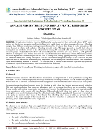
  • 7. International Research Journal of Engineering and Technology (IRJET) e-ISSN: 2395-0056 Volume: 06 Issue: 02 | Feb 2019 www.irjet.net p-ISSN: 2395-0072 One Day National Conference on Recent Advancement in Civil Engineering (RACE 2K19) 25th February 2019 Organized by Department of Civil Engineering, T John Institute of Technology, Bangalore-83 © 2019, IRJET | Impact Factor value: 7.211 | ISO 9001:2008 Certified Journal | Page 1928 Table 3.1 Mesh Convergence Study for interfacial stresses Distance from plateendin mm Stresses in MPa 4mmmesh Stresses in MPa 8mm mesh Stresses in MPa 10mm mesh 0 2.03 1.88 1.68 2 2.26 2.08 1.80 4 1.81 1.76 1.65 6 1.43 1.39 1.31 8 0.83 0.8 0.76 10 0.41 0.39 0.36 12 0.1 0.07 0.064 14 0.096 0.065 0.06 Figure 3.3.Mesh convergence study The boundary conditions adopted for the plated beam is simply supported. It is subjected to a uniformly distributed load of 15N/mm. The material properties of validating model are given in table 3.2. Table 3.2 Properties of validating model
  • 8. International Research Journal of Engineering and Technology (IRJET) e-ISSN: 2395-0056 Volume: 06 Issue: 02 | Feb 2019 www.irjet.net p-ISSN: 2395-0072 One Day National Conference on Recent Advancement in Civil Engineering (RACE 2K19) 25th February 2019 Organized by Department of Civil Engineering, T John Institute of Technology, Bangalore-83 © 2019, IRJET | Impact Factor value: 7.211 | ISO 9001:2008 Certified Journal | Page 1929 Figure 3.5 Interfacial stresses near the plate end. Figure 3.5 explains from observation that the stress pattern near the plate end for the finite element model created for validation in the present study is almost similar to that of the stress behaviour obtained by J.G. Teng et al and there was a little percentage error in the result values due to selection of bigger mesh by considering the computational resource constraints. Since, the mesh size considered by J.G. Teng et al is 0.4mmx0.4mm where as it is 4mmx4mm for the finite element validation model. 3.6. PRESENT STUDY The material properties given in table 3.3 have been used to create the model for analyzing the interfacial stresses in the adhesive layer. The boundary condition adopted is simply supported. The behaviour of interfacial stresses has been investigated by considering the effect of various geometric and mechanical properties of the adherents. Major two cases considered in the present study are the behaviour and influence of interfacial stresses near the plate end for the cause of failure when the beam is subjected to uniformly distributed load and two-point loading. Further, two cases are considered in two-point loading, for the plate when terminated within the constant moment region and the plate extended beyond the constant moment region where the bending moment is minimal. Finite element model of externally plated RC beam is developed in ABAQUS to study the interfacial stress behaviour in the adhesive layer near the plate end. All the elements are modelled with C3D8R linear brick element. The typical finite element model of the plated beam is shown in the figure 3.8. Figure 3.6 Typical view of a plated RC beam subjected to UDL
  • 9. International Research Journal of Engineering and Technology (IRJET) e-ISSN: 2395-0056 Volume: 06 Issue: 02 | Feb 2019 www.irjet.net p-ISSN: 2395-0072 One Day National Conference on Recent Advancement in Civil Engineering (RACE 2K19) 25th February 2019 Organized by Department of Civil Engineering, T John Institute of Technology, Bangalore-83 © 2019, IRJET | Impact Factor value: 7.211 | ISO 9001:2008 Certified Journal | Page 1930 Figure 3.7 Cases considered in plated RC beam subjected to two-point loading Figure 3.8 Typical finite element model of the plated beam Parametric study is carried out with different geometric properties and different soffit plate material. The step analysis considered in the present study is static general. The material properties used in the present study are given in table 3.2. Table 3.3 Properties of present model 4.0. RESULTS AND DISCUSSIONS 4.1 GENERAL A three dimensional finite element model of externally plated reinforced concrete beam is developed with the material properties mentioned in table 3.3 using ABAQUS. In the present study, importance is given mainly to understand the behaviour of interfacial stresses near the plate end.
  • 10. International Research Journal of Engineering and Technology (IRJET) e-ISSN: 2395-0056 Volume: 06 Issue: 02 | Feb 2019 www.irjet.net p-ISSN: 2395-0072 One Day National Conference on Recent Advancement in Civil Engineering (RACE 2K19) 25th February 2019 Organized by Department of Civil Engineering, T John Institute of Technology, Bangalore-83 © 2019, IRJET | Impact Factor value: 7.211 | ISO 9001:2008 Certified Journal | Page 1931 4.2 PARAMETRIC STUDY A parametric study is presented here in which finite element interfacial normal and shear stress behaviour are compared when one of the parameters was varied each time with all the other values as given in Table 3.3 unless otherwise stated to give a more comprehensive assessment of the performance of the plated beams. The beam of Figure 3.6 was taken as the reference beam. The parameters varied in the present study include-  The adhesive layer thickness  The adhesive layer elastic modulus  The soffit plate thickness  The soffit plate material 4.2.1 Loading Two loading conditions are considered in the present study- A uniformly distributed load of 50KN/m is applied along the length of the beam as shown in Figure 3.6 and the parameters are varied in this loading condition alone. Two-point loading of 30KN at each point is applied on the beam by maintaining the dimensions of concrete adherent constant and by varying the length of plate, one by terminating plate within the constant moment region and the other by extending plate beyond CMR where bending moment is minimal as shown in Figure 3.7. 4.2.2 Effect of Adhesive layer thickness Interfacial normal and shear stresses were obtained for four different adhesive layer thicknesses of 1, 2, 3 and 4 mm with all other properties as given in Table 3.3. Both the interfacial normal and shear stresses are shown in Figures 4.1 and 4.2 respectively for the region near the plate end. Figure 4.1 Effect of adhesive layer thickness on interfacial normal stress
  • 11. International Research Journal of Engineering and Technology (IRJET) e-ISSN: 2395-0056 Volume: 06 Issue: 02 | Feb 2019 www.irjet.net p-ISSN: 2395-0072 One Day National Conference on Recent Advancement in Civil Engineering (RACE 2K19) 25th February 2019 Organized by Department of Civil Engineering, T John Institute of Technology, Bangalore-83 © 2019, IRJET | Impact Factor value: 7.211 | ISO 9001:2008 Certified Journal | Page 1932 Figure 4.2 Effect of adhesive layer thickness on interfacial shear stress It can be seen that reducing the thickness of the adhesive layer leads to an increase in both the normal stress (Figure 4.1) and the shear stress (Figure 4.2). The peak interfacial normal stress occurs near the end of the plate. At the end of the plate, the interfacial shear stress values are slightly tending towards zero. The peak finite element shear stress occurs at a short distance from the end of the plate, rather than at the end of the plate. Table 4.1 Peak interfacial stresses for different adhesive layer thickness 4.2.3 Effect of adhesive elastic modulus The effect of varying the elastic modulus of the adhesive is shown in Figures 4.3 and 4.4. As the elastic modulus of the adhesive is increased, the interfacial normal and shear stresses also increase. Figure 4.3 Effect of adhesive elastic modulus on interfacial normal stress
  • 12. International Research Journal of Engineering and Technology (IRJET) e-ISSN: 2395-0056 Volume: 06 Issue: 02 | Feb 2019 www.irjet.net p-ISSN: 2395-0072 One Day National Conference on Recent Advancement in Civil Engineering (RACE 2K19) 25th February 2019 Organized by Department of Civil Engineering, T John Institute of Technology, Bangalore-83 © 2019, IRJET | Impact Factor value: 7.211 | ISO 9001:2008 Certified Journal | Page 1933 The plate length considered in case-1 is assumed to be 800mm, while all the other properties are as per mentioned in table 3.3. It is observed that the peak stresses are obtained near the plate end in both the cases; stresses are highly increased near the plate end in the case where plate is terminated in CMR when compared to case-2. Figure 4.10 and 4.11 shows the stress contours for case-1 and case-2 respectively. Figure 4.10 Stress contour when the plate is terminated within CMR Figure 4.11 Stress contour when plate is extended beyond CMR 4.3 STRESS CONTOURS The observation of stress contours helps to understand the interfacial stress behaviour very easily. The most common pattern of the stress contour has been observed in almost all the cases in the present study with the stresses starting high near the plate end and gradually decreasing along the length of plate. Figure 4.12 and 4.13 shows the stresses observed in adhesive layer. Figure 4.12 Stress contour of adhesive when plate is terminated in CMR Figure 4.13 Stress contour of adhesive layer for beam subjected to UDL
  • 13. International Research Journal of Engineering and Technology (IRJET) e-ISSN: 2395-0056 Volume: 06 Issue: 02 | Feb 2019 www.irjet.net p-ISSN: 2395-0072 One Day National Conference on Recent Advancement in Civil Engineering (RACE 2K19) 25th February 2019 Organized by Department of Civil Engineering, T John Institute of Technology, Bangalore-83 © 2019, IRJET | Impact Factor value: 7.211 | ISO 9001:2008 Certified Journal | Page 1934 5.0. CONCLUSIONS 5.1. SUMMARY A careful finite element investigation into interfacial stresses in reinforced concrete (RC) beams strengthened with a bonded soffit plate has been dealt in the present study. The present study was focused on the behaviour of interfacial shear and normal stresses in the adhesive layer near the plate end. The parametric study is done when one of the parameters was varied each time with all the other values as given in Table 3.3 unless otherwise stated to give a more comprehensive assessment of the performance of the plated beams when they are subjected to uniformly distributed load. Another loading condition is also considered in the present study i.e. to assess the influence of the position of plate termination on the interfacial stresses under two-point loading. 5.2. CONCLUSIONS Based on the results of finite element analysis, the following conclusions are derived.  In general, it is observed that, Uniform stress distributions in the adhesive layer as assumed in early existing approximate analytical solutions are found at a small distance away from the end of the plate.  To analyze externally plated RC beams for accurate determination of the interfacial stresses, a very fine mesh has to be used so that the effect of any further mesh refinement is reduced to a zone near the end of the plate.  Finite element results showed that stresses vary strongly in the adhesive layer, in particular near the end of the plate.  Under the action of uniformly distribute load, the following conclusion are derived from the parametric study. The interfacial stresses were found to increase with a reduction in adhesive layer thickness, and peak stress values are obtained near the plate end then the stress distribution is almost uniform a little away from end of the plate.  The interfacial stresses were found to increase with an increase in adhesive elastic modulus and plate thickness.  The effect of adhesive elastic modulus haven’t shown any significant variation in adhesive stresses whereas, the variation in adhesive thickness have shown significant influence on stress distribution particularly near the plate end.  The replacement of CFRP to steel plate has shown a considerable amount of reduction in peak stresses.  Under the action of two-point loading  Termination of plate within the constant moment region is resulting to very strong variation in stresses near the plate end and the peak values are high compared to case of which plate extended beyond CMR.  It is found feasible to terminate plate at a position where bending moment is minimal for a better performance of the beam. Further parametric studies in this case and consideration of shear deformation effect helps for complete assessment of stress distributions. By considering all the above conclusions and existing design a predictive model can be prepared in practical approach which helps for better performance of structure. 5.3. FUTURE SCOPE OF WORK An experimental approach is to be carried out with the specifications of analytical model used in the present study.  Comparative studies are to be done for Finite element model and experimental model.  Consideration of shear deformation effect on interfacial stresses has a great scope in future work.  Values thus obtained are to be verified with the existing analytical solutions and conclusions can be declared on the interfacial stress influence on failure modes.
  • 14. International Research Journal of Engineering and Technology (IRJET) e-ISSN: 2395-0056 Volume: 06 Issue: 02 | Feb 2019 www.irjet.net p-ISSN: 2395-0072 One Day National Conference on Recent Advancement in Civil Engineering (RACE 2K19) 25th February 2019 Organized by Department of Civil Engineering, T John Institute of Technology, Bangalore-83 © 2019, IRJET | Impact Factor value: 7.211 | ISO 9001:2008 Certified Journal | Page 1935 REFERENCES 1) ABAQUS user’s manual, Version 6.11. (2011). Dassault Systemes Simulia Corp., Providence, RI, USA. 2) Tim Stratford, John Cadei (2006) “Elastic analysis of adhesion stresses for the design of a strengthening plate bonded to a beam”, Construction and Building Materials 20 (2006) 34–45. 3) Narayanamurthy V, J.F.Chen, J. Cairns, A. Ramaswamy (2011) “Effect of shear deformation on interfacial stresses in plated beams subjected to arbitrary loading”, International Journal of Adhesion & Adhesives 31 (2011) 862–874. 4) Teng J.G., J.W. Zhang, S.T. Smith (2001) “Interfacial stresses in reinforced concrete beams bonded with a soffit plate: a finite element study”, Construction and Building Materials 16(2002).1-4. 5) Abu Thomas Zachariah (2006) “Finite Element Modelling of Adhesive Interface between Steel and CFRP”, Chalmers, Civil and Environmental Engineering, Master’s Thesis 2006:61. 6) S.T. Smith, J.G. Teng (2000) “Interfacial stresses in plated beams”, Engineering Structures 23 (2001) 857–871.