SlideShare a Scribd company logo
1 of 11
Download to read offline
Fifteen steps of molding design and design focus
A mold is an industrial product that shapes a material by a certain structure in a specific structure,
and is also a production tool capable of mass-producing industrial product parts having a certain
shape and size requirement. Large to airplanes, cars, small cups, nails, almost all industrial
products must rely on molding. High precision, high consistency, and high productivity of parts
produced by mold are unmatched by any other processing method. Molds largely determine
quality, efficiency and new product development capabilities of product. Therefore, mold has
honorary title of “Mother of Industry”.
Mold designer refers to personnel who are engaged in digital design of enterprise molds,
including cavity molds and cold stamping molds, and fully applied digital design tools to improve
molding design quality and shorten molding design cycle on the basis of traditional molding
design. Mold designer can be employed in the fields of CNC programming, mold 3D design, and
product development 3D design.
 Step 1: Analysis and digestion of 2D/3D drawing of product, content
includes following aspects:
1. Geometry of product.
2, Size, tolerance and design basis of product.
3. Technical requirements of product (ie technical conditions).
4. Name, shrinkage and color of plastic used in product.
5. Surface requirements of product.
 Step 2: Determination of injection machine type
Specification of injection is mainly determined by size and production volume of plastic product.
When designing injection machine, designer mainly considers plasticizing rate, injection volume,
clamping force, effective area of mounting mold (spacing inside injection rod), modulus, top
ejection form and determined length. If customer has provided type or specification of injectable
use, designer must check parameters and if it does not meet requirements, it must be consulted
with customer.
 Step 3: Determination of number and layout of cavities
Determination of number of mold cavity is mainly determined by projected area of product,
geometry (with or without side cores), accuracy of product, batch size, and economic benefits.
Number of mold cavity is determined mainly by following factors:
1. Production batch of products (monthly batch or annual batch).
2. Whether product has side core and its treatment method.
3. Outer dimensions of mold and effective area of injection molding (or spacing inside injection
rod).
4. Weight of product and injection volume of injection machine.
5. Projected area and clamping force of product.
6, Product accuracy.
7, Product color.
8. Economic benefits (production value of each set of molds).
These factors are sometimes mutually constrained, so when designing a design, coordination
must be made to ensure that main conditions are met.
After number of cavities is determined, arrangement of cavities and layout of cavity positions are
performed. Arrangement of cavities involves size of mold, design of gating system, balance of
gating system, design of core (slider) mechanism, design of insert core, and design of hot runner
system. These problems are related to selection of parting surface and gate position, so in
specific design process, necessary adjustments must be made to achieve most perfect design.
 Step 4: Determination of parting surface
Parting surface has been specified in some foreign product drawings, but in many molding design,
it is determined by mold personnel. Generally speaking, parting surface on the plane is easier to
handle. Sometimes you should pay special attention to three-dimensional parting surface.
Selection of parting surface should follow following principles:
1, Does not affect appearance of product, especially for products with clear requirements on
appearance, should pay attention to impact of shape on the appearance.
2, To ensure accuracy of product.
3, Conducive to molding process, especially processing of cavity.
4. Conducive to design of gating system, exhaust system and cooling system.
5. It is beneficial to demoulding product to ensure that product is left on movable mold side
when mold is opened.
6, Easy to metal inserts.
When designing lateral parting mechanism, it should be ensured that it is safe and reliable, avoid
interference with fixed mechanism as much as possible. Otherwise, a pre-recovery mechanism
should be set on mold.
 Step 5: Determination of mold base and selection of standard parts
After all above contents are determined, mold base is designed according to specified content.
When designing formwork, use standard formwork as much as possible to determine form,
specifications and thickness of A/B plates of standard formwork. Standard parts include two
types: common standard parts and standard parts for molds. General standard parts such as
fasteners. Standard parts for molds such as positioning ring, sprue bushing, push rod, push tube,
guide post, guide sleeve, mold-specific spring, cooling and heating element, secondary parting
mechanism and standard components for precision positioning.
It should be emphasized that when designing molds, standard mold base and standard parts are
used as much as possible, because a large part of standard parts have been commercialized and
can be purchased at any time, which is extremely advantageous for shortening manufacturing
cycle and reducing manufacturing cost.
After buyer has been sized, necessary strength and rigidity calculations are performed on
mold-related parts to check that selected formwork is appropriate, especially for large molds.
 Step 6: Design of gating system
Design of gating system includes selection of main flow path, shape of cross-section of runner,
and determination of dimensions.
If a point gate is used, in order to ensure separation of runner, attention should also be paid to
design of degasser.
In designing gating system, first is to choose location of gate. Appropriate choice of location of
gate will directly affect quality of product and smoothness of injection process. Choice of gate
location should follow following principles:
1. Position of gate should be selected on parting surface as much as possible to facilitate
processing of mold and cleaning of gate.
2. Distance between gate location and various parts of cavity should be as uniform as possible,
and process should be the shortest (it is difficult to do with a large nozzle).
3. Position of gate should ensure that plastic is injected into cavity against spacious and
thick-walled part of cavity to facilitate inflow of plastic.
4. Avoid plastics from penetrating into cavity wall, core or insert when flowing into cavity, so that
plastics can flow into all parts of cavity as soon as possible to avoid deformation of core or insert.
5, Try to avoid production of weld lines. If it is to be produced, make dissolution marks appear in
places where product is not important.
6. Position of gate and direction of plastic injection should be, plastic can flow uniformly along
parallel direction of cavity when injecting into cavity, and it is beneficial to discharge of gas in
cavity.
7. Gate should be designed to be the easiest part to remove on product, while not affecting
appearance of product as much as possible.
 Step 7: Design of ejection system
Ejector form of product can be divided into three categories: mechanical ejection, hydraulic
ejection, and pneumatic ejection.
Mechanical ejection is the last link in injection molding process. Quality of ejection will
ultimately determine quality of product. Therefore, product ejection cannot be ignored.
Following principles should be observed when designing an ejector system:
1. In order to prevent product from being deformed due to ejection, thrust point should be as
close as possible to core or part that is difficult to demould. For example, elongated hollow
cylinder on product is mostly pushed out by a push tube. Arrangement of thrust points should be
as balanced as possible.
2. Thrust point should be applied to part where product can withstand the most stress and part
with good rigidity, such as rib, flange, wall edge of shell type product, etc.
3, Try to avoid thrust point on thinner surface of product, to prevent product from whitening, top
height, etc., such as shell-shaped products and cylindrical products are mostly pushed out by
push plates.
4, Try to avoid appearance of product, ejection device should be placed on hidden or
non-decorative surface of product. In particular, attention should be paid to choice of position
and ejection form for transparent articles.
5. In order to make product evenly stressed when it is ejected, and avoid deformation of product
due to vacuum adsorption, a composite ejection or special form of ejector system, such as push
rod, push plate or push rod, push tube composite, is often used. To eject, or use air intake push
rod, push block, etc. If necessary, an intake valve should also be provided.
 Step 8: Design of cooling system
Design of cooling system is a cumbersome task, considering cooling effect, uniformity of cooling
and effect of cooling system on overall structure of mold. Design of cooling system includes
following:
1. Arrangement and specific form of cooling system.
2. Determination of specific location and size of cooling system.
3. Key parts are the cooling of the dynamic model core or insert.
4. Cooling of side slider and side slide core.
5. Design of cooling components and selection of cooling standard components.
6. Design of sealing structure.
Layout of Cavity Cooling System
Layout of Core Cooling System
 Step 9: Design of guide device
Guides on plastic injection mold have been determined using standard mold base. Under normal
circumstances, designer only needs to select according to mold base specifications. However,
when a precision guide is required according to requirements of product, it must be designed by
designer according to mold structure.
General orientation is divided into: orientation between moving and fixed molds; guiding of push
plate and push rod fixing plate; guiding between pushing plate and moving plate; guiding
between fixed die seat and push pirated version. Generally, guiding device is limited by
processing precision or after a period of use, precision of matching is lowered, which directly
affects precision of product. Therefore, precision positioning component must be separately
designed for product with high precision. Some have been standardized, such as tapered
positioning pins, positioning blocks, etc., but some precision guiding and positioning devices
must be specially designed according to specific structure of module.
 Step 10: Selection of mold steel
Selection of materials for mold forming parts (cavities, cores) is mainly determined according to
batch size and plastic type of products. For products with high gloss or transparency, martensitic
corrosion resistant stainless steel or age hardened steel of type 4Cr13 is mainly used.
For plastic products containing glass fiber reinforced, quenched steel with high wear resistance
such as Cr12MoV should be used.
When material of product is PVC, POM or contains a flame retardant, corrosion resistant stainless
steel must be used.
 Step 11: Drawing fit chart
After aligning formwork and related content is determined, assembly drawing can be drawn. In
process of assembly drawing, further coordination and improvement of selected gating system,
cooling system, core pulling system, ejector system, to achieve a more perfect design from
structure.
 Step 12: Drawing of mold main part
When design a cavity or core drawing, necessary molding dimensions, tolerances, and draft
angles are coordinated, and design basis is coordinated with design basis of product. At the same
time, it is also necessary to consider processability of cavity and core during processing,
mechanical properties and reliability during use.
When design a structural part drawing, when a standard formwork is used, most of structural
parts other than standard formwork may not be drawn.
 Step 13: Proofreading of design drawings
After mold drawing design is completed, mold designer will submit design drawings and related
original materials to supervisor for proofreading.
Proofreading personnel shall systematically proofread overall structure, working principle and
feasibility of mold according to relevant design basis and requirements provided by customer.
 Step 14: Designing drawing
Once mold design drawings are completed, they must be submitted to customer for approval.
Only after customer agrees, mold can be put into production. When a customer has a large
opinion that requires major changes, it must be re-designed and then handed over to customer
for approval until customer is satisfied.
 Step 15: Designing exhaust system
Exhaust system plays a vital role in ensuring quality of product. Exhaust methods are as follows:
1. Use exhaust slot. Venting groove is generally located at portion where cavity is finally filled.
Depth of venting groove varies from plastic and is essentially determined by maximum clearance
allowed when plastic does not create a flash.
2. Use matching clearance of core, insert, push rod, or special exhaust plug to exhaust.
3, Sometimes in order to prevent vacuum deformation of product in the top, it is necessary to
design exhaust insert.
 Conclusion
Combine above molding design procedures, some of which can be considered together, and
some content should be considered repeatedly. Because factors are often contradictory, they
must be continuously demonstrated and coordinated in design process to get better treatment.
In particular, content related to mold structure must be taken seriously, and often several
solutions should be considered at the same time. For each structure, list advantages and
disadvantages of each aspect as much as possible, and analyzes them one by one to optimize.
Structural reasons will directly affect manufacture and use of mold, serious consequences will
even cause entire mold to be scrapped. Therefore, molding design is a key step to ensure quality
of mold, and its design process is a systematic project.
 Key points in mold design:
1. Reasonable overall layout of mold.
2, Choice of parting surface
3, Layout of flow channel, selection of gate
4, Ejection device
5, Water distribution
6, Choice of exhaust
7. Pay attention to draft angle when mold is divided, extraction of insert, treatment of rubbing
angle, and shrinkage of material.
8, Processing drawing should be detailed, but simple.
 How do we simplify mold structure to the greatest extent possible?
On one hand, when reviewing products with customers, it is necessary to highlight problems of
mold release brought by product to mold opening, whether to improve products: on other hand,
whether meeting is held in the company before mold design, soliciting various feasible structural
proposals to determine final plan from perspective of customer requirements.
1. Feasibility analysis of products of designed molds. Taking computer case as an example, firstly,
assembly drawings of each component are analyzed by design software, that is, set of drawings
mentioned in the work to ensure correctness of drawings of each product before molding design.
On other hand, you can familiarize yourself with importance of each component in whole chassis
to determine key size, which is very beneficial in mold design.
2. After product analysis, analyze product using mold structure, carry out process of product,
determine content of each process, and use design software to carry out product development.
When product is launched, it generally starts from subsequent project, for example, a product
requires five processes, stamping is completed from product drawing to fourth, third, second,
and first projects, a graphic is copied and then previous project is executed. That is, product of
five projects is completed, and then detailed work is carried out. Note that this step is very
important and needs to be very careful. If this step is completed well, it will save a lot of time in
drawing mold diagram. After stamping content of each project is determined, including in the
forming mold, inner and outer lines of thickness of product material are retained to determine
size of convex and concave molds.
3. Prepare materials. According to product development drawing, determine size of template in
drawings, including fixed plates, unloading plates, convex and concave molds, inserts, etc., pay
attention to preparation directly in product development drawing, which is of great benefit to
drawing of mold drawing. I have seen some mold designer directly calculate product drawing to
prepare material. This method is too inefficient, draw template size directly on the drawing, and
express it in form of a group diagram. In terms of preparation of materials, on other hand, a lot of
work is saved in work of various parts of mold, because in work of drawing each component, it is
only necessary to add positioning, pins, guide posts and screw holes in preparation drawing.
4. After preparation is completed, mold drawing can be fully entered, and a copy can be made in
preparation drawing to draw components, such as adding screw holes, guide post holes,
positioning holes, etc. And in punching die. Hole for each hole needs to be cut by wire. In forming
die, forming gap of upper and lower molds must not be forgotten, so mold drawing of one
product after completion of these work is almost completed 80%, In addition, in process of
designing mold drawing, it is necessary to pay attention to: each process, refers to production,
such as fitter scribing, wire cutting, etc. to different processing steps have a complete production
of layer, which has great benefits for wire cutting and drawing management, such as color
distinction, etc. Dimensional marking is also a very important job, and it is also the most
troublesome job, because it is too time consuming.
5. After above drawings are completed, drawings cannot be issued. It is also necessary to
proofread mold drawings, assemble all accessories, make different layers for each different mold
plate, and use same basis as guide post holes to perform mold. Insert product development
drawings into group diagrams to ensure that hole positions of template are consistent and gap
between upper and lower molds of bending position is correct.
Sixteen steps of mold design and design focus

More Related Content

What's hot

What's hot (20)

Injection moulding
Injection mouldingInjection moulding
Injection moulding
 
Engineering Guidelines to Designing Plastic Parts for Injection Molding
Engineering Guidelines to Designing Plastic Parts for Injection MoldingEngineering Guidelines to Designing Plastic Parts for Injection Molding
Engineering Guidelines to Designing Plastic Parts for Injection Molding
 
Sheet Metal Operations
Sheet Metal OperationsSheet Metal Operations
Sheet Metal Operations
 
Sand Casting
Sand Casting Sand Casting
Sand Casting
 
Manufacturing Technology 1 full unit notes
Manufacturing Technology 1 full unit notesManufacturing Technology 1 full unit notes
Manufacturing Technology 1 full unit notes
 
4.patterns
4.patterns4.patterns
4.patterns
 
Types of dies
Types of diesTypes of dies
Types of dies
 
Casting
CastingCasting
Casting
 
Plastic Molding Defects
Plastic Molding DefectsPlastic Molding Defects
Plastic Molding Defects
 
9.special casting processes
9.special casting processes9.special casting processes
9.special casting processes
 
ppt on Sheet metal process
ppt on Sheet metal processppt on Sheet metal process
ppt on Sheet metal process
 
FDM FUSED DEPOSITION MODELLING
FDM FUSED DEPOSITION MODELLINGFDM FUSED DEPOSITION MODELLING
FDM FUSED DEPOSITION MODELLING
 
Pattern making
Pattern makingPattern making
Pattern making
 
Casting
CastingCasting
Casting
 
Chapter 1 introduction to casting process
Chapter 1 introduction to casting processChapter 1 introduction to casting process
Chapter 1 introduction to casting process
 
Pro E/Mold Design (Pro/MOLDESIGN)
Pro E/Mold Design (Pro/MOLDESIGN)Pro E/Mold Design (Pro/MOLDESIGN)
Pro E/Mold Design (Pro/MOLDESIGN)
 
Plastic injection moulding
Plastic injection mouldingPlastic injection moulding
Plastic injection moulding
 
Design for Plastics
Design for Plastics Design for Plastics
Design for Plastics
 
Design for Manufacturing-Module 5
Design for Manufacturing-Module 5 Design for Manufacturing-Module 5
Design for Manufacturing-Module 5
 
ISOTHERMAL FORGING
ISOTHERMAL FORGINGISOTHERMAL FORGING
ISOTHERMAL FORGING
 

Similar to Sixteen steps of mold design and design focus

DESIGN OF MOULD TOOL & COOLING CHANNEL OPTIMIZATION OF REMOTE CONTROL TOP PANEL
DESIGN OF MOULD TOOL & COOLING CHANNEL OPTIMIZATION OF REMOTE CONTROL TOP PANELDESIGN OF MOULD TOOL & COOLING CHANNEL OPTIMIZATION OF REMOTE CONTROL TOP PANEL
DESIGN OF MOULD TOOL & COOLING CHANNEL OPTIMIZATION OF REMOTE CONTROL TOP PANELIjripublishers Ijri
 
Project Report File of Mouldflow Analysis
Project Report File of Mouldflow AnalysisProject Report File of Mouldflow Analysis
Project Report File of Mouldflow AnalysisJatinder Singh
 
Conceptual design of injection mold tool for the chair hand rest component
Conceptual design of injection mold tool for the chair hand rest componentConceptual design of injection mold tool for the chair hand rest component
Conceptual design of injection mold tool for the chair hand rest componenteSAT Publishing House
 
IRJET-Design Optimization of Mold for Dust Proof Cap
IRJET-Design Optimization of Mold for Dust Proof CapIRJET-Design Optimization of Mold for Dust Proof Cap
IRJET-Design Optimization of Mold for Dust Proof CapIRJET Journal
 
Industrial Trainig report fdocxhshjjdlvgeiheqkddwy
Industrial Trainig report fdocxhshjjdlvgeiheqkddwyIndustrial Trainig report fdocxhshjjdlvgeiheqkddwy
Industrial Trainig report fdocxhshjjdlvgeiheqkddwyssuserc4e7cc1
 
The ROI of Improved Injection Molding Process Flow
The ROI of Improved Injection Molding Process FlowThe ROI of Improved Injection Molding Process Flow
The ROI of Improved Injection Molding Process FlowKaysun Corporation
 
How to design injection molding product?
How to design injection molding product?How to design injection molding product?
How to design injection molding product?JasmineHL
 
A Design and Analysis of Two Plate Injection Mould Tool For Wi-Fi RouterTherm...
A Design and Analysis of Two Plate Injection Mould Tool For Wi-Fi RouterTherm...A Design and Analysis of Two Plate Injection Mould Tool For Wi-Fi RouterTherm...
A Design and Analysis of Two Plate Injection Mould Tool For Wi-Fi RouterTherm...EditorJST
 
The ROI of Improved Project Flow: How Injection Molders Impact Outcomes
The ROI of Improved Project Flow: How Injection Molders Impact OutcomesThe ROI of Improved Project Flow: How Injection Molders Impact Outcomes
The ROI of Improved Project Flow: How Injection Molders Impact OutcomesKaysun Corporation
 
A Review on Design of Fixtures
A Review on Design of FixturesA Review on Design of Fixtures
A Review on Design of FixturesLaukik Raut
 
Demystifying Designing for ‘X’ by ProTek Medical
Demystifying Designing for ‘X’ by ProTek Medical Demystifying Designing for ‘X’ by ProTek Medical
Demystifying Designing for ‘X’ by ProTek Medical ProtekMedical
 
6 points about ejector pins help your injection molding work increase 50%!
6 points about ejector pins help your injection molding work increase 50%!6 points about ejector pins help your injection molding work increase 50%!
6 points about ejector pins help your injection molding work increase 50%!JasmineHL
 
Know about injection moulding copy
Know about injection moulding   copyKnow about injection moulding   copy
Know about injection moulding copyBhushan Gadilohar
 
A Review on Design of a Fixture for Rear Cover
A Review on Design of a Fixture for Rear CoverA Review on Design of a Fixture for Rear Cover
A Review on Design of a Fixture for Rear Coverijsrd.com
 
IRJET- Design and Development of Gear Shift Boot Die
IRJET- Design and Development of Gear Shift Boot DieIRJET- Design and Development of Gear Shift Boot Die
IRJET- Design and Development of Gear Shift Boot DieIRJET Journal
 
IRJET- Simulation for Optimum Gate Location in Plastic Injection Moulding for...
IRJET- Simulation for Optimum Gate Location in Plastic Injection Moulding for...IRJET- Simulation for Optimum Gate Location in Plastic Injection Moulding for...
IRJET- Simulation for Optimum Gate Location in Plastic Injection Moulding for...IRJET Journal
 

Similar to Sixteen steps of mold design and design focus (20)

DESIGN OF MOULD TOOL & COOLING CHANNEL OPTIMIZATION OF REMOTE CONTROL TOP PANEL
DESIGN OF MOULD TOOL & COOLING CHANNEL OPTIMIZATION OF REMOTE CONTROL TOP PANELDESIGN OF MOULD TOOL & COOLING CHANNEL OPTIMIZATION OF REMOTE CONTROL TOP PANEL
DESIGN OF MOULD TOOL & COOLING CHANNEL OPTIMIZATION OF REMOTE CONTROL TOP PANEL
 
DESIGN OF MOULD TOOL & COOLING CHANNEL OPTIMIZATION OF REMOTE CONTROL TOP PANEL
DESIGN OF MOULD TOOL & COOLING CHANNEL OPTIMIZATION OF REMOTE CONTROL TOP PANELDESIGN OF MOULD TOOL & COOLING CHANNEL OPTIMIZATION OF REMOTE CONTROL TOP PANEL
DESIGN OF MOULD TOOL & COOLING CHANNEL OPTIMIZATION OF REMOTE CONTROL TOP PANEL
 
Project Report File of Mouldflow Analysis
Project Report File of Mouldflow AnalysisProject Report File of Mouldflow Analysis
Project Report File of Mouldflow Analysis
 
Conceptual design of injection mold tool for the chair hand rest component
Conceptual design of injection mold tool for the chair hand rest componentConceptual design of injection mold tool for the chair hand rest component
Conceptual design of injection mold tool for the chair hand rest component
 
Mt2421032111
Mt2421032111Mt2421032111
Mt2421032111
 
IRJET-Design Optimization of Mold for Dust Proof Cap
IRJET-Design Optimization of Mold for Dust Proof CapIRJET-Design Optimization of Mold for Dust Proof Cap
IRJET-Design Optimization of Mold for Dust Proof Cap
 
polymer processing ppt
polymer processing  pptpolymer processing  ppt
polymer processing ppt
 
Industrial Trainig report fdocxhshjjdlvgeiheqkddwy
Industrial Trainig report fdocxhshjjdlvgeiheqkddwyIndustrial Trainig report fdocxhshjjdlvgeiheqkddwy
Industrial Trainig report fdocxhshjjdlvgeiheqkddwy
 
The ROI of Improved Injection Molding Process Flow
The ROI of Improved Injection Molding Process FlowThe ROI of Improved Injection Molding Process Flow
The ROI of Improved Injection Molding Process Flow
 
How to design injection molding product?
How to design injection molding product?How to design injection molding product?
How to design injection molding product?
 
A Design and Analysis of Two Plate Injection Mould Tool For Wi-Fi RouterTherm...
A Design and Analysis of Two Plate Injection Mould Tool For Wi-Fi RouterTherm...A Design and Analysis of Two Plate Injection Mould Tool For Wi-Fi RouterTherm...
A Design and Analysis of Two Plate Injection Mould Tool For Wi-Fi RouterTherm...
 
The ROI of Improved Project Flow: How Injection Molders Impact Outcomes
The ROI of Improved Project Flow: How Injection Molders Impact OutcomesThe ROI of Improved Project Flow: How Injection Molders Impact Outcomes
The ROI of Improved Project Flow: How Injection Molders Impact Outcomes
 
A Review on Design of Fixtures
A Review on Design of FixturesA Review on Design of Fixtures
A Review on Design of Fixtures
 
Demystifying Designing for ‘X’ by ProTek Medical
Demystifying Designing for ‘X’ by ProTek Medical Demystifying Designing for ‘X’ by ProTek Medical
Demystifying Designing for ‘X’ by ProTek Medical
 
6 points about ejector pins help your injection molding work increase 50%!
6 points about ejector pins help your injection molding work increase 50%!6 points about ejector pins help your injection molding work increase 50%!
6 points about ejector pins help your injection molding work increase 50%!
 
Minimization of Sink Mark Defects in Injection Molding Process
Minimization of Sink Mark Defects in Injection Molding ProcessMinimization of Sink Mark Defects in Injection Molding Process
Minimization of Sink Mark Defects in Injection Molding Process
 
Know about injection moulding copy
Know about injection moulding   copyKnow about injection moulding   copy
Know about injection moulding copy
 
A Review on Design of a Fixture for Rear Cover
A Review on Design of a Fixture for Rear CoverA Review on Design of a Fixture for Rear Cover
A Review on Design of a Fixture for Rear Cover
 
IRJET- Design and Development of Gear Shift Boot Die
IRJET- Design and Development of Gear Shift Boot DieIRJET- Design and Development of Gear Shift Boot Die
IRJET- Design and Development of Gear Shift Boot Die
 
IRJET- Simulation for Optimum Gate Location in Plastic Injection Moulding for...
IRJET- Simulation for Optimum Gate Location in Plastic Injection Moulding for...IRJET- Simulation for Optimum Gate Location in Plastic Injection Moulding for...
IRJET- Simulation for Optimum Gate Location in Plastic Injection Moulding for...
 

More from Gud Mould Industry Limited

Design of Injection Mold for Breast Shield with In.pdf
Design of Injection Mold for Breast Shield with In.pdfDesign of Injection Mold for Breast Shield with In.pdf
Design of Injection Mold for Breast Shield with In.pdfGud Mould Industry Limited
 
A complete collection of plastic parts design tech.pdf
A complete collection of plastic parts design tech.pdfA complete collection of plastic parts design tech.pdf
A complete collection of plastic parts design tech.pdfGud Mould Industry Limited
 
Design of injection mold for door trim panel of SA.pdf
Design of injection mold for door trim panel of SA.pdfDesign of injection mold for door trim panel of SA.pdf
Design of injection mold for door trim panel of SA.pdfGud Mould Industry Limited
 
Analysis of the development trend of the global an.pdf
Analysis of the development trend of the global an.pdfAnalysis of the development trend of the global an.pdf
Analysis of the development trend of the global an.pdfGud Mould Industry Limited
 
Design of injection mould for 135° elbow pipe of i
Design of injection mould for 135° elbow pipe of iDesign of injection mould for 135° elbow pipe of i
Design of injection mould for 135° elbow pipe of iGud Mould Industry Limited
 
Mould Design Sharing-Design of Gating System (Part 1)
Mould Design Sharing-Design of Gating System (Part 1)Mould Design Sharing-Design of Gating System (Part 1)
Mould Design Sharing-Design of Gating System (Part 1)Gud Mould Industry Limited
 
Hot runner nozzle cooling method and its influence
Hot runner nozzle cooling method and its influenceHot runner nozzle cooling method and its influence
Hot runner nozzle cooling method and its influenceGud Mould Industry Limited
 
36 common plastic raw materials molding temperature that you must know
36 common plastic raw materials molding temperature that you must know36 common plastic raw materials molding temperature that you must know
36 common plastic raw materials molding temperature that you must knowGud Mould Industry Limited
 
Quenching, tempering, normalizing, annealing, do you know clearly?
Quenching, tempering, normalizing, annealing, do you know clearly?Quenching, tempering, normalizing, annealing, do you know clearly?
Quenching, tempering, normalizing, annealing, do you know clearly?Gud Mould Industry Limited
 
Analysis of common faults in hot runner systems
Analysis of common faults in hot runner systemsAnalysis of common faults in hot runner systems
Analysis of common faults in hot runner systemsGud Mould Industry Limited
 
36 common plastic raw materials molding temperatur
36 common plastic raw materials molding temperatur36 common plastic raw materials molding temperatur
36 common plastic raw materials molding temperaturGud Mould Industry Limited
 
Analysis and elimination of gas mark in plastic pr
Analysis and elimination of gas mark in plastic prAnalysis and elimination of gas mark in plastic pr
Analysis and elimination of gas mark in plastic prGud Mould Industry Limited
 

More from Gud Mould Industry Limited (15)

Design of Injection Mold for Breast Shield with In.pdf
Design of Injection Mold for Breast Shield with In.pdfDesign of Injection Mold for Breast Shield with In.pdf
Design of Injection Mold for Breast Shield with In.pdf
 
A complete collection of plastic parts design tech.pdf
A complete collection of plastic parts design tech.pdfA complete collection of plastic parts design tech.pdf
A complete collection of plastic parts design tech.pdf
 
Design of injection mold for door trim panel of SA.pdf
Design of injection mold for door trim panel of SA.pdfDesign of injection mold for door trim panel of SA.pdf
Design of injection mold for door trim panel of SA.pdf
 
Analysis of the principle of plastic flow.pdf
Analysis of the principle of plastic flow.pdfAnalysis of the principle of plastic flow.pdf
Analysis of the principle of plastic flow.pdf
 
Analysis of the development trend of the global an.pdf
Analysis of the development trend of the global an.pdfAnalysis of the development trend of the global an.pdf
Analysis of the development trend of the global an.pdf
 
Design of injection mould for 135° elbow pipe of i
Design of injection mould for 135° elbow pipe of iDesign of injection mould for 135° elbow pipe of i
Design of injection mould for 135° elbow pipe of i
 
Gud 2021-1
Gud 2021-1Gud 2021-1
Gud 2021-1
 
Presentation of Gud Mould Industry Limited
Presentation of Gud Mould Industry LimitedPresentation of Gud Mould Industry Limited
Presentation of Gud Mould Industry Limited
 
Mould Design Sharing-Design of Gating System (Part 1)
Mould Design Sharing-Design of Gating System (Part 1)Mould Design Sharing-Design of Gating System (Part 1)
Mould Design Sharing-Design of Gating System (Part 1)
 
Hot runner nozzle cooling method and its influence
Hot runner nozzle cooling method and its influenceHot runner nozzle cooling method and its influence
Hot runner nozzle cooling method and its influence
 
36 common plastic raw materials molding temperature that you must know
36 common plastic raw materials molding temperature that you must know36 common plastic raw materials molding temperature that you must know
36 common plastic raw materials molding temperature that you must know
 
Quenching, tempering, normalizing, annealing, do you know clearly?
Quenching, tempering, normalizing, annealing, do you know clearly?Quenching, tempering, normalizing, annealing, do you know clearly?
Quenching, tempering, normalizing, annealing, do you know clearly?
 
Analysis of common faults in hot runner systems
Analysis of common faults in hot runner systemsAnalysis of common faults in hot runner systems
Analysis of common faults in hot runner systems
 
36 common plastic raw materials molding temperatur
36 common plastic raw materials molding temperatur36 common plastic raw materials molding temperatur
36 common plastic raw materials molding temperatur
 
Analysis and elimination of gas mark in plastic pr
Analysis and elimination of gas mark in plastic prAnalysis and elimination of gas mark in plastic pr
Analysis and elimination of gas mark in plastic pr
 

Recently uploaded

IAC 2024 - IA Fast Track to Search Focused AI Solutions
IAC 2024 - IA Fast Track to Search Focused AI SolutionsIAC 2024 - IA Fast Track to Search Focused AI Solutions
IAC 2024 - IA Fast Track to Search Focused AI SolutionsEnterprise Knowledge
 
Kotlin Multiplatform & Compose Multiplatform - Starter kit for pragmatics
Kotlin Multiplatform & Compose Multiplatform - Starter kit for pragmaticsKotlin Multiplatform & Compose Multiplatform - Starter kit for pragmatics
Kotlin Multiplatform & Compose Multiplatform - Starter kit for pragmaticscarlostorres15106
 
Swan(sea) Song – personal research during my six years at Swansea ... and bey...
Swan(sea) Song – personal research during my six years at Swansea ... and bey...Swan(sea) Song – personal research during my six years at Swansea ... and bey...
Swan(sea) Song – personal research during my six years at Swansea ... and bey...Alan Dix
 
My Hashitalk Indonesia April 2024 Presentation
My Hashitalk Indonesia April 2024 PresentationMy Hashitalk Indonesia April 2024 Presentation
My Hashitalk Indonesia April 2024 PresentationRidwan Fadjar
 
Hyderabad Call Girls Khairatabad ✨ 7001305949 ✨ Cheap Price Your Budget
Hyderabad Call Girls Khairatabad ✨ 7001305949 ✨ Cheap Price Your BudgetHyderabad Call Girls Khairatabad ✨ 7001305949 ✨ Cheap Price Your Budget
Hyderabad Call Girls Khairatabad ✨ 7001305949 ✨ Cheap Price Your BudgetEnjoy Anytime
 
Integration and Automation in Practice: CI/CD in Mule Integration and Automat...
Integration and Automation in Practice: CI/CD in Mule Integration and Automat...Integration and Automation in Practice: CI/CD in Mule Integration and Automat...
Integration and Automation in Practice: CI/CD in Mule Integration and Automat...Patryk Bandurski
 
FULL ENJOY 🔝 8264348440 🔝 Call Girls in Diplomatic Enclave | Delhi
FULL ENJOY 🔝 8264348440 🔝 Call Girls in Diplomatic Enclave | DelhiFULL ENJOY 🔝 8264348440 🔝 Call Girls in Diplomatic Enclave | Delhi
FULL ENJOY 🔝 8264348440 🔝 Call Girls in Diplomatic Enclave | Delhisoniya singh
 
Tech-Forward - Achieving Business Readiness For Copilot in Microsoft 365
Tech-Forward - Achieving Business Readiness For Copilot in Microsoft 365Tech-Forward - Achieving Business Readiness For Copilot in Microsoft 365
Tech-Forward - Achieving Business Readiness For Copilot in Microsoft 3652toLead Limited
 
Presentation on how to chat with PDF using ChatGPT code interpreter
Presentation on how to chat with PDF using ChatGPT code interpreterPresentation on how to chat with PDF using ChatGPT code interpreter
Presentation on how to chat with PDF using ChatGPT code interpreternaman860154
 
Injustice - Developers Among Us (SciFiDevCon 2024)
Injustice - Developers Among Us (SciFiDevCon 2024)Injustice - Developers Among Us (SciFiDevCon 2024)
Injustice - Developers Among Us (SciFiDevCon 2024)Allon Mureinik
 
Pigging Solutions in Pet Food Manufacturing
Pigging Solutions in Pet Food ManufacturingPigging Solutions in Pet Food Manufacturing
Pigging Solutions in Pet Food ManufacturingPigging Solutions
 
Breaking the Kubernetes Kill Chain: Host Path Mount
Breaking the Kubernetes Kill Chain: Host Path MountBreaking the Kubernetes Kill Chain: Host Path Mount
Breaking the Kubernetes Kill Chain: Host Path MountPuma Security, LLC
 
SQL Database Design For Developers at php[tek] 2024
SQL Database Design For Developers at php[tek] 2024SQL Database Design For Developers at php[tek] 2024
SQL Database Design For Developers at php[tek] 2024Scott Keck-Warren
 
Slack Application Development 101 Slides
Slack Application Development 101 SlidesSlack Application Development 101 Slides
Slack Application Development 101 Slidespraypatel2
 
Automating Business Process via MuleSoft Composer | Bangalore MuleSoft Meetup...
Automating Business Process via MuleSoft Composer | Bangalore MuleSoft Meetup...Automating Business Process via MuleSoft Composer | Bangalore MuleSoft Meetup...
Automating Business Process via MuleSoft Composer | Bangalore MuleSoft Meetup...shyamraj55
 
Advanced Test Driven-Development @ php[tek] 2024
Advanced Test Driven-Development @ php[tek] 2024Advanced Test Driven-Development @ php[tek] 2024
Advanced Test Driven-Development @ php[tek] 2024Scott Keck-Warren
 
CloudStudio User manual (basic edition):
CloudStudio User manual (basic edition):CloudStudio User manual (basic edition):
CloudStudio User manual (basic edition):comworks
 
Azure Monitor & Application Insight to monitor Infrastructure & Application
Azure Monitor & Application Insight to monitor Infrastructure & ApplicationAzure Monitor & Application Insight to monitor Infrastructure & Application
Azure Monitor & Application Insight to monitor Infrastructure & ApplicationAndikSusilo4
 

Recently uploaded (20)

IAC 2024 - IA Fast Track to Search Focused AI Solutions
IAC 2024 - IA Fast Track to Search Focused AI SolutionsIAC 2024 - IA Fast Track to Search Focused AI Solutions
IAC 2024 - IA Fast Track to Search Focused AI Solutions
 
The transition to renewables in India.pdf
The transition to renewables in India.pdfThe transition to renewables in India.pdf
The transition to renewables in India.pdf
 
Kotlin Multiplatform & Compose Multiplatform - Starter kit for pragmatics
Kotlin Multiplatform & Compose Multiplatform - Starter kit for pragmaticsKotlin Multiplatform & Compose Multiplatform - Starter kit for pragmatics
Kotlin Multiplatform & Compose Multiplatform - Starter kit for pragmatics
 
Swan(sea) Song – personal research during my six years at Swansea ... and bey...
Swan(sea) Song – personal research during my six years at Swansea ... and bey...Swan(sea) Song – personal research during my six years at Swansea ... and bey...
Swan(sea) Song – personal research during my six years at Swansea ... and bey...
 
My Hashitalk Indonesia April 2024 Presentation
My Hashitalk Indonesia April 2024 PresentationMy Hashitalk Indonesia April 2024 Presentation
My Hashitalk Indonesia April 2024 Presentation
 
E-Vehicle_Hacking_by_Parul Sharma_null_owasp.pptx
E-Vehicle_Hacking_by_Parul Sharma_null_owasp.pptxE-Vehicle_Hacking_by_Parul Sharma_null_owasp.pptx
E-Vehicle_Hacking_by_Parul Sharma_null_owasp.pptx
 
Hyderabad Call Girls Khairatabad ✨ 7001305949 ✨ Cheap Price Your Budget
Hyderabad Call Girls Khairatabad ✨ 7001305949 ✨ Cheap Price Your BudgetHyderabad Call Girls Khairatabad ✨ 7001305949 ✨ Cheap Price Your Budget
Hyderabad Call Girls Khairatabad ✨ 7001305949 ✨ Cheap Price Your Budget
 
Integration and Automation in Practice: CI/CD in Mule Integration and Automat...
Integration and Automation in Practice: CI/CD in Mule Integration and Automat...Integration and Automation in Practice: CI/CD in Mule Integration and Automat...
Integration and Automation in Practice: CI/CD in Mule Integration and Automat...
 
FULL ENJOY 🔝 8264348440 🔝 Call Girls in Diplomatic Enclave | Delhi
FULL ENJOY 🔝 8264348440 🔝 Call Girls in Diplomatic Enclave | DelhiFULL ENJOY 🔝 8264348440 🔝 Call Girls in Diplomatic Enclave | Delhi
FULL ENJOY 🔝 8264348440 🔝 Call Girls in Diplomatic Enclave | Delhi
 
Tech-Forward - Achieving Business Readiness For Copilot in Microsoft 365
Tech-Forward - Achieving Business Readiness For Copilot in Microsoft 365Tech-Forward - Achieving Business Readiness For Copilot in Microsoft 365
Tech-Forward - Achieving Business Readiness For Copilot in Microsoft 365
 
Presentation on how to chat with PDF using ChatGPT code interpreter
Presentation on how to chat with PDF using ChatGPT code interpreterPresentation on how to chat with PDF using ChatGPT code interpreter
Presentation on how to chat with PDF using ChatGPT code interpreter
 
Injustice - Developers Among Us (SciFiDevCon 2024)
Injustice - Developers Among Us (SciFiDevCon 2024)Injustice - Developers Among Us (SciFiDevCon 2024)
Injustice - Developers Among Us (SciFiDevCon 2024)
 
Pigging Solutions in Pet Food Manufacturing
Pigging Solutions in Pet Food ManufacturingPigging Solutions in Pet Food Manufacturing
Pigging Solutions in Pet Food Manufacturing
 
Breaking the Kubernetes Kill Chain: Host Path Mount
Breaking the Kubernetes Kill Chain: Host Path MountBreaking the Kubernetes Kill Chain: Host Path Mount
Breaking the Kubernetes Kill Chain: Host Path Mount
 
SQL Database Design For Developers at php[tek] 2024
SQL Database Design For Developers at php[tek] 2024SQL Database Design For Developers at php[tek] 2024
SQL Database Design For Developers at php[tek] 2024
 
Slack Application Development 101 Slides
Slack Application Development 101 SlidesSlack Application Development 101 Slides
Slack Application Development 101 Slides
 
Automating Business Process via MuleSoft Composer | Bangalore MuleSoft Meetup...
Automating Business Process via MuleSoft Composer | Bangalore MuleSoft Meetup...Automating Business Process via MuleSoft Composer | Bangalore MuleSoft Meetup...
Automating Business Process via MuleSoft Composer | Bangalore MuleSoft Meetup...
 
Advanced Test Driven-Development @ php[tek] 2024
Advanced Test Driven-Development @ php[tek] 2024Advanced Test Driven-Development @ php[tek] 2024
Advanced Test Driven-Development @ php[tek] 2024
 
CloudStudio User manual (basic edition):
CloudStudio User manual (basic edition):CloudStudio User manual (basic edition):
CloudStudio User manual (basic edition):
 
Azure Monitor & Application Insight to monitor Infrastructure & Application
Azure Monitor & Application Insight to monitor Infrastructure & ApplicationAzure Monitor & Application Insight to monitor Infrastructure & Application
Azure Monitor & Application Insight to monitor Infrastructure & Application
 

Sixteen steps of mold design and design focus

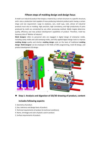
  • 1. Fifteen steps of molding design and design focus A mold is an industrial product that shapes a material by a certain structure in a specific structure, and is also a production tool capable of mass-producing industrial product parts having a certain shape and size requirement. Large to airplanes, cars, small cups, nails, almost all industrial products must rely on molding. High precision, high consistency, and high productivity of parts produced by mold are unmatched by any other processing method. Molds largely determine quality, efficiency and new product development capabilities of product. Therefore, mold has honorary title of “Mother of Industry”. Mold designer refers to personnel who are engaged in digital design of enterprise molds, including cavity molds and cold stamping molds, and fully applied digital design tools to improve molding design quality and shorten molding design cycle on the basis of traditional molding design. Mold designer can be employed in the fields of CNC programming, mold 3D design, and product development 3D design.  Step 1: Analysis and digestion of 2D/3D drawing of product, content includes following aspects: 1. Geometry of product. 2, Size, tolerance and design basis of product. 3. Technical requirements of product (ie technical conditions). 4. Name, shrinkage and color of plastic used in product. 5. Surface requirements of product.
  • 2.  Step 2: Determination of injection machine type Specification of injection is mainly determined by size and production volume of plastic product. When designing injection machine, designer mainly considers plasticizing rate, injection volume, clamping force, effective area of mounting mold (spacing inside injection rod), modulus, top ejection form and determined length. If customer has provided type or specification of injectable use, designer must check parameters and if it does not meet requirements, it must be consulted with customer.  Step 3: Determination of number and layout of cavities Determination of number of mold cavity is mainly determined by projected area of product, geometry (with or without side cores), accuracy of product, batch size, and economic benefits. Number of mold cavity is determined mainly by following factors: 1. Production batch of products (monthly batch or annual batch). 2. Whether product has side core and its treatment method. 3. Outer dimensions of mold and effective area of injection molding (or spacing inside injection rod). 4. Weight of product and injection volume of injection machine. 5. Projected area and clamping force of product. 6, Product accuracy. 7, Product color. 8. Economic benefits (production value of each set of molds). These factors are sometimes mutually constrained, so when designing a design, coordination must be made to ensure that main conditions are met. After number of cavities is determined, arrangement of cavities and layout of cavity positions are performed. Arrangement of cavities involves size of mold, design of gating system, balance of gating system, design of core (slider) mechanism, design of insert core, and design of hot runner system. These problems are related to selection of parting surface and gate position, so in specific design process, necessary adjustments must be made to achieve most perfect design.
  • 3.  Step 4: Determination of parting surface Parting surface has been specified in some foreign product drawings, but in many molding design, it is determined by mold personnel. Generally speaking, parting surface on the plane is easier to handle. Sometimes you should pay special attention to three-dimensional parting surface. Selection of parting surface should follow following principles: 1, Does not affect appearance of product, especially for products with clear requirements on appearance, should pay attention to impact of shape on the appearance. 2, To ensure accuracy of product. 3, Conducive to molding process, especially processing of cavity. 4. Conducive to design of gating system, exhaust system and cooling system. 5. It is beneficial to demoulding product to ensure that product is left on movable mold side when mold is opened. 6, Easy to metal inserts. When designing lateral parting mechanism, it should be ensured that it is safe and reliable, avoid interference with fixed mechanism as much as possible. Otherwise, a pre-recovery mechanism should be set on mold.
  • 4.  Step 5: Determination of mold base and selection of standard parts After all above contents are determined, mold base is designed according to specified content. When designing formwork, use standard formwork as much as possible to determine form, specifications and thickness of A/B plates of standard formwork. Standard parts include two types: common standard parts and standard parts for molds. General standard parts such as fasteners. Standard parts for molds such as positioning ring, sprue bushing, push rod, push tube, guide post, guide sleeve, mold-specific spring, cooling and heating element, secondary parting mechanism and standard components for precision positioning. It should be emphasized that when designing molds, standard mold base and standard parts are used as much as possible, because a large part of standard parts have been commercialized and can be purchased at any time, which is extremely advantageous for shortening manufacturing cycle and reducing manufacturing cost. After buyer has been sized, necessary strength and rigidity calculations are performed on mold-related parts to check that selected formwork is appropriate, especially for large molds.  Step 6: Design of gating system Design of gating system includes selection of main flow path, shape of cross-section of runner, and determination of dimensions. If a point gate is used, in order to ensure separation of runner, attention should also be paid to design of degasser. In designing gating system, first is to choose location of gate. Appropriate choice of location of gate will directly affect quality of product and smoothness of injection process. Choice of gate location should follow following principles: 1. Position of gate should be selected on parting surface as much as possible to facilitate processing of mold and cleaning of gate. 2. Distance between gate location and various parts of cavity should be as uniform as possible, and process should be the shortest (it is difficult to do with a large nozzle). 3. Position of gate should ensure that plastic is injected into cavity against spacious and thick-walled part of cavity to facilitate inflow of plastic.
  • 5. 4. Avoid plastics from penetrating into cavity wall, core or insert when flowing into cavity, so that plastics can flow into all parts of cavity as soon as possible to avoid deformation of core or insert. 5, Try to avoid production of weld lines. If it is to be produced, make dissolution marks appear in places where product is not important. 6. Position of gate and direction of plastic injection should be, plastic can flow uniformly along parallel direction of cavity when injecting into cavity, and it is beneficial to discharge of gas in cavity. 7. Gate should be designed to be the easiest part to remove on product, while not affecting appearance of product as much as possible.  Step 7: Design of ejection system Ejector form of product can be divided into three categories: mechanical ejection, hydraulic ejection, and pneumatic ejection. Mechanical ejection is the last link in injection molding process. Quality of ejection will ultimately determine quality of product. Therefore, product ejection cannot be ignored. Following principles should be observed when designing an ejector system: 1. In order to prevent product from being deformed due to ejection, thrust point should be as close as possible to core or part that is difficult to demould. For example, elongated hollow cylinder on product is mostly pushed out by a push tube. Arrangement of thrust points should be as balanced as possible. 2. Thrust point should be applied to part where product can withstand the most stress and part with good rigidity, such as rib, flange, wall edge of shell type product, etc. 3, Try to avoid thrust point on thinner surface of product, to prevent product from whitening, top height, etc., such as shell-shaped products and cylindrical products are mostly pushed out by push plates. 4, Try to avoid appearance of product, ejection device should be placed on hidden or non-decorative surface of product. In particular, attention should be paid to choice of position and ejection form for transparent articles. 5. In order to make product evenly stressed when it is ejected, and avoid deformation of product
  • 6. due to vacuum adsorption, a composite ejection or special form of ejector system, such as push rod, push plate or push rod, push tube composite, is often used. To eject, or use air intake push rod, push block, etc. If necessary, an intake valve should also be provided.  Step 8: Design of cooling system Design of cooling system is a cumbersome task, considering cooling effect, uniformity of cooling and effect of cooling system on overall structure of mold. Design of cooling system includes following: 1. Arrangement and specific form of cooling system. 2. Determination of specific location and size of cooling system. 3. Key parts are the cooling of the dynamic model core or insert. 4. Cooling of side slider and side slide core. 5. Design of cooling components and selection of cooling standard components. 6. Design of sealing structure.
  • 7. Layout of Cavity Cooling System Layout of Core Cooling System  Step 9: Design of guide device Guides on plastic injection mold have been determined using standard mold base. Under normal circumstances, designer only needs to select according to mold base specifications. However, when a precision guide is required according to requirements of product, it must be designed by designer according to mold structure. General orientation is divided into: orientation between moving and fixed molds; guiding of push plate and push rod fixing plate; guiding between pushing plate and moving plate; guiding between fixed die seat and push pirated version. Generally, guiding device is limited by processing precision or after a period of use, precision of matching is lowered, which directly affects precision of product. Therefore, precision positioning component must be separately designed for product with high precision. Some have been standardized, such as tapered positioning pins, positioning blocks, etc., but some precision guiding and positioning devices must be specially designed according to specific structure of module.  Step 10: Selection of mold steel Selection of materials for mold forming parts (cavities, cores) is mainly determined according to batch size and plastic type of products. For products with high gloss or transparency, martensitic corrosion resistant stainless steel or age hardened steel of type 4Cr13 is mainly used. For plastic products containing glass fiber reinforced, quenched steel with high wear resistance such as Cr12MoV should be used. When material of product is PVC, POM or contains a flame retardant, corrosion resistant stainless steel must be used.  Step 11: Drawing fit chart After aligning formwork and related content is determined, assembly drawing can be drawn. In process of assembly drawing, further coordination and improvement of selected gating system, cooling system, core pulling system, ejector system, to achieve a more perfect design from structure.
  • 8.  Step 12: Drawing of mold main part When design a cavity or core drawing, necessary molding dimensions, tolerances, and draft angles are coordinated, and design basis is coordinated with design basis of product. At the same time, it is also necessary to consider processability of cavity and core during processing, mechanical properties and reliability during use. When design a structural part drawing, when a standard formwork is used, most of structural parts other than standard formwork may not be drawn.  Step 13: Proofreading of design drawings After mold drawing design is completed, mold designer will submit design drawings and related original materials to supervisor for proofreading. Proofreading personnel shall systematically proofread overall structure, working principle and feasibility of mold according to relevant design basis and requirements provided by customer.  Step 14: Designing drawing Once mold design drawings are completed, they must be submitted to customer for approval. Only after customer agrees, mold can be put into production. When a customer has a large opinion that requires major changes, it must be re-designed and then handed over to customer for approval until customer is satisfied.  Step 15: Designing exhaust system Exhaust system plays a vital role in ensuring quality of product. Exhaust methods are as follows: 1. Use exhaust slot. Venting groove is generally located at portion where cavity is finally filled. Depth of venting groove varies from plastic and is essentially determined by maximum clearance allowed when plastic does not create a flash. 2. Use matching clearance of core, insert, push rod, or special exhaust plug to exhaust. 3, Sometimes in order to prevent vacuum deformation of product in the top, it is necessary to design exhaust insert.  Conclusion
  • 9. Combine above molding design procedures, some of which can be considered together, and some content should be considered repeatedly. Because factors are often contradictory, they must be continuously demonstrated and coordinated in design process to get better treatment. In particular, content related to mold structure must be taken seriously, and often several solutions should be considered at the same time. For each structure, list advantages and disadvantages of each aspect as much as possible, and analyzes them one by one to optimize. Structural reasons will directly affect manufacture and use of mold, serious consequences will even cause entire mold to be scrapped. Therefore, molding design is a key step to ensure quality of mold, and its design process is a systematic project.  Key points in mold design: 1. Reasonable overall layout of mold. 2, Choice of parting surface 3, Layout of flow channel, selection of gate 4, Ejection device 5, Water distribution 6, Choice of exhaust 7. Pay attention to draft angle when mold is divided, extraction of insert, treatment of rubbing angle, and shrinkage of material. 8, Processing drawing should be detailed, but simple.  How do we simplify mold structure to the greatest extent possible? On one hand, when reviewing products with customers, it is necessary to highlight problems of mold release brought by product to mold opening, whether to improve products: on other hand, whether meeting is held in the company before mold design, soliciting various feasible structural proposals to determine final plan from perspective of customer requirements. 1. Feasibility analysis of products of designed molds. Taking computer case as an example, firstly, assembly drawings of each component are analyzed by design software, that is, set of drawings mentioned in the work to ensure correctness of drawings of each product before molding design. On other hand, you can familiarize yourself with importance of each component in whole chassis to determine key size, which is very beneficial in mold design. 2. After product analysis, analyze product using mold structure, carry out process of product,
  • 10. determine content of each process, and use design software to carry out product development. When product is launched, it generally starts from subsequent project, for example, a product requires five processes, stamping is completed from product drawing to fourth, third, second, and first projects, a graphic is copied and then previous project is executed. That is, product of five projects is completed, and then detailed work is carried out. Note that this step is very important and needs to be very careful. If this step is completed well, it will save a lot of time in drawing mold diagram. After stamping content of each project is determined, including in the forming mold, inner and outer lines of thickness of product material are retained to determine size of convex and concave molds. 3. Prepare materials. According to product development drawing, determine size of template in drawings, including fixed plates, unloading plates, convex and concave molds, inserts, etc., pay attention to preparation directly in product development drawing, which is of great benefit to drawing of mold drawing. I have seen some mold designer directly calculate product drawing to prepare material. This method is too inefficient, draw template size directly on the drawing, and express it in form of a group diagram. In terms of preparation of materials, on other hand, a lot of work is saved in work of various parts of mold, because in work of drawing each component, it is only necessary to add positioning, pins, guide posts and screw holes in preparation drawing. 4. After preparation is completed, mold drawing can be fully entered, and a copy can be made in preparation drawing to draw components, such as adding screw holes, guide post holes, positioning holes, etc. And in punching die. Hole for each hole needs to be cut by wire. In forming die, forming gap of upper and lower molds must not be forgotten, so mold drawing of one product after completion of these work is almost completed 80%, In addition, in process of designing mold drawing, it is necessary to pay attention to: each process, refers to production, such as fitter scribing, wire cutting, etc. to different processing steps have a complete production of layer, which has great benefits for wire cutting and drawing management, such as color distinction, etc. Dimensional marking is also a very important job, and it is also the most troublesome job, because it is too time consuming. 5. After above drawings are completed, drawings cannot be issued. It is also necessary to proofread mold drawings, assemble all accessories, make different layers for each different mold plate, and use same basis as guide post holes to perform mold. Insert product development drawings into group diagrams to ensure that hole positions of template are consistent and gap between upper and lower molds of bending position is correct.