Hot runner nozzle cooling method and its influence
•
0 likes•40 views

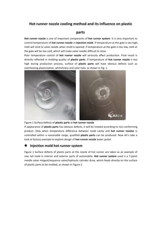
Hot runner nozzle is one of important components of hot runner system. It is very important to control temperature of hot runner nozzle in injection mold. If temperature at the gate is too high, melt will stick to valve needle when mold is opened. If temperature at the gate is too low, melt at the gate will be too cold, which will make valve needle difficult to close.

Recommended
Recommended
More Related Content
Similar to Hot runner nozzle cooling method and its influence
Similar to Hot runner nozzle cooling method and its influence (20)
More from Gud Mould Industry Limited
More from Gud Mould Industry Limited (11)
Recently uploaded
Recently uploaded (20)
Hot runner nozzle cooling method and its influence
- 1. Hot runner nozzle cooling method and its influence on plastic parts Hot runner nozzle is one of important components of hot runner system. It is very important to control temperature of hot runner nozzle in injection mold. If temperature at the gate is too high, melt will stick to valve needle when mold is opened. If temperature at the gate is too low, melt at the gate will be too cold, which will make valve needle difficult to close. Poor temperature control of hot runner nozzle will seriously affect production. Final result is directly reflected in molding quality of plastic parts. If temperature of hot runner nozzle is too high during production process, surface of plastic parts will have obvious defects such as overheating plasticization, whitishness and solar halo, as shown in Fig. 1. Figure 1 Surface defects of plastic parts at hot runner nozzle If appearance of plastic parts has obvious defects, it will be treated according to non-conforming product. Only when temperature difference between mold cavity and hot runner nozzles is controlled within a reasonable range, qualified plastic parts can be produced. Now let's take a look at factory example to explore design of hot runner nozzle water jacket. Injection mold hot runner system Figure 1 Surface defects of plastic parts at the nozzle of hot runner are taken as an example of rear tail mold in interior and exterior parts of automobile. Hot runner system used is a 7-point needle valve integral/sequence valve/hydraulic cylinder drive, which feeds directly on the surface of plastic parts to be molded, as shown in Figure 2.
- 2. Figure 2 hot runner system Figure 3 Cooling water channel in hot runner system Circulating cooling water circuit in hot runner system is shown in Figure 3. Its function is to insulate heat transfer between hot runner plate and hydraulic cylinder to ensure normal operation and service life of hydraulic cylinder.
- 3. Figure 4 Water/oil inlet and outlet manifold Cooling water channel in hot runner system is generally in series, and each series is not allowed to exceed 3 points. As shown in Fig. 4, on water/oil inlet and outlet block, there are 5 sets of cooling water inlet and outlet ports on water/oil inlet and outlet block, but each cylinder in hot runner system controls 1 needle valve feed point, and each requires water cooling. There are 7 feed points in rear-end mold hot runner system (see Figure 2), where two feed points are connected in series to meet series requirements of hot runner system. Valve needle drive cylinder of hot runner system is generally divided into two types: hydraulic cylinder drive and cylinder drive. Under same conditions, cylinder block volume is larger than hydraulic cylinder volume. Pressure of hydraulic cylinder is large but not environmentally friendly, pressure of cylinder is small and environmentally friendly. Mold in the example is driven by a hydraulic cylinder due to weight of plastic parts, length of hot nozzle, and injection pressure. Plastic parts process analysis Molded plastic part is rear side tail in interior and exterior parts of automobile, process analysis is shown in Fig. 5.
- 4. Figure 5 Plastic parts process analysis Plastic parts are made of PP+T20, outer dimensions are 1320mm*758mm*329mm, mass is 1.853kg, and average wall thickness is 2.2mm. Recommended mold temperature is 45 ℃ . Recommended plastic melting temperature is 220 ℃ , ejection temperature is 124 ℃ , and maximum shear rate is 100000 s-1. Warpage analysis requires that temperature difference of molded parts in mold should be controlled at ±20℃. Hot runner nozzle cooling For design of cooling water channel of hot runner nozzle, after years of tracking and improvement, style is continuously optimized and innovated to meet characteristics, cost control of manufactured mold. Following is a list of several hot nozzle cooling waterway design schemes. Nozzle cooling scheme 1
- 5. Figure 6 Waterway styles provided by hot runner manufacturers and actual designed waterway locations For automotive interior and exterior trim injection molds, manufacturer provides a hot runner system with hot water on both sides of nozzle. As shown in Figure 6, mold for forming inner and outer trim is generally medium and large molds with complex molding surfaces or parting surfaces around feed point. Figure 7 Recommended range of water channel distance When there is no large plane around feeding point to provide position of water channel, cooling water channel should be designed as evenly as possible under conditions allowed by mold structure. Water channel diameter should be as large as possible, quantity should be as large as possible. Distance between cooling water channel and cavity surface should be as equal as possible, as shown in Figure 7. Among them, hot runner nozzle needs to be reinforced by heat. When designing waterway around nozzle, distance is usually smaller than that of normal waterway. Therefore, it is necessary to design a better cooling waterway scheme. Nozzle cooling scheme 2
- 6. Figure 8 Adding inserts at feed point Adding one insert at feeding point of plastic parts, as shown in Fig. 8. It can avoid complicated arrangement of molding surface or parting surface, which makes waterway arrangement difficult, so that water path arranged can ensure temperature of insert is consistent with that of mold cavity, and surface quality of plastic parts is ensured. Nozzle cooling scheme 3 Figure 9 Designing water towers and inclined waterways around feed point For feed point locations that are not suitable for designing inserts, water towers can be designed around feed point, as shown in Figure 9, and oblique waterway cooling can be designed. However, cooling effect of water tower an oblique waterway is not ideal, because water tower and oblique waterway are far away from feeding point, there is a certain temperature difference between center of feeding point and cooling water tower, which has a certain influence on surface quality of molded plastic part, and is not the best production state. Nozzle cooling scheme 4
- 7. Figure 10 hot nozzle cooling water jacket On the basis of designing water tower, cooling effect of feed point is further improved, and one annular water path is designed for hot nozzle, that is, one hot nozzle cooling water jacket is added, as shown in FIG 10. Cooling water jacket is simple to process, convenient to install, and uniform in cooling. Disadvantage is that nozzle is not cooled enough, and there is a certain distance from feeding point. Temperature at nozzle is not optimal temperature, and temperature is also adjusted by mold cavity and mold temperature machine. Nozzle cooling scheme 5 Figure 11 with waterway inserts Surface quality of plastic parts is relatively high. Hot nozzle inserts need to be evenly cooled, size is small, and parts are compact. Water-filled inserts can be used, as shown in Figure 11. Cooling effect of contoured waterway insert is very good, but cost is also high.
- 8. Figure 12: Separate processing of water-filled inserts Conformal waterway insert is a brazed insert that divides part into several pieces, processes preset water path on split block, and brazes it into one part, leaving a 1.5~3mm finishing allowance for shape, such as Figure 12 shows. Disadvantage is that it can not be argon-arc welded. If temperature exceeds 400℃, solder in conformal waterway insert will melt and parts will leak, but higher cost laser welding can be used. In addition, thickness of brazed position of segmented block cannot be greater than 30 mm, otherwise quality of segmented block will be affected. Internal shape of insert waterway insert is complicated, and traditional processing method will be limited. However, it can be formed by a new processing method. One is a 3D printed molding part, which can meet requirements of mold, and hardness of part can reach 46~50HRC. Internal quality and surface quality of parts are also qualified; second is diffusion welding, which is similar to brazed manufacturing of water-filled inserts. Parts are first divided into several pieces, and preset water path is processed on divided pieces, but welding methods are different. Diffusion welding does not require soldering, but processing requirements are high, surface roughness of parts is very high, which is equivalent to mirror surface. Split blocks are pressed together and high temperature is added. It takes several days to make divided blocks bond well together, and properties of entire material are obtained after successful welding. Regardless of whether conformal waterway insert is brazed, diffusion welded, or 3D printed, cooling water used inside insert must be purified water. If ordinary cooling water is used, mold will last for a long time, and scale will precipitate in the waterway. It is difficult to clean on the wall of water pipe, and it will reduce cooling effect of cooling water. Poor thermal conductivity will cause mold cooling condition to deteriorate. With this complicated insert water path, injection mold has a good cooling effect, but later mold use cost and maintenance cost are high. In addition, cost of hot nozzle water jacket for processing contoured waterway insert is also high. Nozzle cooling scheme 6
- 9. Figure 13 Integral hot nozzle cooling water jacket At present, commonly used integral hot nozzle water jacket is shown in Fig. 13. This cooling method can not only cool nozzle water jacket head in place, but also has simple processing technology, convenient disassembly and maintenance. For example, rear side tail mold has 7 feeding points, corresponding to 7 integral hot nozzle water jackets, each water jacket has a separate cooling water circuit. Under temperature control of external mold temperature machine, it is easier to achieve same temperature as rear side injection mold cavity. It has been verified by multiple molds that structure of water jacket is reliable, cooling water flows evenly on water jacket, and manufacturing process is simple. On this basis, water jacket is further standardized. Water jacket material is made of hot-working die steel SKD61 with a hardness of 50~55HRC. Standard external dimension is φ 89mm*200mm. Material of single water jacket and all processing and molding costs are about 2,000 yuan. Mold flow analysis and test mode verification After mold flow analysis, result is obtained through test mold verification. Mold of side tail after molding uses hot nozzle water jacket, cooling effect is obvious, cooling time is reduced by 3~4s in a single production cycle, and production of similar parts is generally performed. Cycle is 45s, and now it is directly reduced to 41s (see Figure 14). Production efficiency has increased by more than 8%, saving resources.
- 10. Figure 14 rear side tail feed filling pattern and production cycle Figure 15 High surface quality plastic parts After verification by multiple molds, surface quality of molded parts was compared, as shown in Fig. 15. By designing integral hot nozzle cooling water jacket, not only high surface quality molded parts are obtained, but also cooling effect is good, which is important for improving quality of molded plastic parts and shortening production cycle.