Design of injection mold for door trim panel of SA.pdf
•
0 likes•35 views

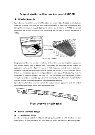
Figure 1 shows interior trim panel of left front door of a certain model. This door panel adopts an integrated structure. Trim panel and horn grille are integrated on door panel interior panel, and horn grille is honeycomb-shaped. Door panel interior panel material is PP-T20, the overall dimensions are 885mm*718mm*122mm, main body wall thickness is 2.2mm, and weight is 1780g.

Recommended
Recommended
More Related Content
Similar to Design of injection mold for door trim panel of SA.pdf
Similar to Design of injection mold for door trim panel of SA.pdf (20)
More from Gud Mould Industry Limited
More from Gud Mould Industry Limited (10)
Recently uploaded
Recently uploaded (20)
Design of injection mold for door trim panel of SA.pdf
- 1. Design of injection mold for door trim panel of SAIC GM 1 Product Analysis Figure 1 shows interior trim panel of left front door of a certain model. This door panel adopts an integrated structure. Trim panel and horn grille are integrated on door panel interior panel, and horn grille is honeycomb-shaped. Door panel interior panel material is PP-T20, the overall dimensions are 885mm*718mm*122mm, main body wall thickness is 2.2mm, and weight is 1780g. Design points of door trim panel are as follows: ① Door trim panel is an important appearance skin pattern, defects such as welding lines, flow marks, and shrinkage are not allowed on appearance surface; ② Door trim panel is high-frequency contact part of customers. Appearance parting line of product should be invisible and smooth to touch, especially parting lines in upper decorative panel area and glove box area are exposed. The two parting lines are not allowed to have step difference and flash; ③ Door trim panel is directly assembled on sheet metal, there can be no assembly gap with sheet metal parts, and deformation of product after injection molding is required to be within controllable range of loading. Figure 2 shows front door water-cut bracket. This product is a non-appearance part. It is welded and installed in decorative area of front door interior panel. 2 Mold structure design 2.1 Mold layout design In order to improve production efficiency of door panel, combined with structure and size characteristics of front door panel, left front door trim panel, left front door water-cut bracket,
- 2. right front door trim panel, and right front door water-cut bracket are designed to be formed on a pair of molds, mold adopts the layout of "1+1+1+1", as shown in Figure 3. 2.2 Design of mold gating system 2.2.1 Determination of gate quantity and gate location Due to large size of front door trim panel and existence of a horn grille structure, it is not easy to fill, so it is necessary to design multi-point feeding. After optimization and analysis of Moldflow, it is decided that a single front door trim panel adopts a 10-point needle valve feeding scheme, left/right water-cut brackets share a 2-point needle valve hot runner. Layout of feeding point is shown in Figure 4. Among them, points 1, 2, 3, 4, 5, 6, 7, 8, and 10 use side gates, and gate size is 15mm*1.2mm;
- 3. point 9 is located on door opening side of car door, and uses horn lurking gates. Size is 6mm*1mm; point 11 and 12 use side gates, and gate size is 20mm*1.2mm. Inner diameter of hot runner is φ22mm, diameter of valve needle is φ8mm, and diameter of hot runner gate is φ 6mm. After repeated optimization and analysis by Moldflow, it was finally determined that opening sequence of hot runner sequence valve of a single front door trim panel is: point 1→point 2/3/4 →point 5/6→point 7/8/9→point 10, hot runner sequence valve opening sequence of left/right front door water cut bracket is point 11→point 12. Among them, point 1 and point 11 are turned on at the same time. Analysis results of Moldflow weld lines are shown in Figure 5. Weld lines are all located in non-appearance area because there are many mounting holes in this area. The overall appearance area is well filled and meets design requirements. Deformation analysis results of Moldflow products are shown in Figure 6. Deformation in X, Y, and Z directions of product is small, mainly shrinkage deformation, and the overall deformation is relatively uniform, which meets product design requirements.
- 4. 2.2.2 Design of hot runner sequence valve Design of hot runner sequence valve is shown in Figure 7. According to analysis results of Moldflow, mold adopts a 22-point hot runner sequence valve design. 2.3 Main mechanism of mold Main mechanisms of mold include insert structure in upper decorative plate area, insert structure in sundries box area, door panel horn mesh cover ejection mechanism, and oblique push mechanism, as shown in Figure 8.
- 5. 2.3.1 Large insert structure Since door trim panel is a product that is frequently contacted by customers, parting line in upper trim panel area and glove box area is exposed, can be touched by hand, in order to ensure quality of parting line in these two areas, insert structure is designed on mold respectively. , as shown in Fig. 9(a). In order to ensure quality of parting line and improve matching accuracy of inserts, positioning bosses are designed on both upper decorative plate inserts and sundries box inserts, as shown in Figure 9(b). Positioning boss has two main functions: ① During mold assembly process, insert is locked on mold cavity plate through positioning boss, so as to correct parting line segment difference; ② During injection process, inserts are interlocked in mold cavity through positioning bosses to avoid dislocation and deformation of mold parts due to excessive injection pressure, and improve quality of parting line. In addition, two inserts are designed with cooling water circuits to cool inserts during injection. 2.3.2 Horn grille pop-up mechanism In order to ensure smooth demoulding of door panel horn grille mesh, ejector mechanism is designed, including step push rod, ejector push rod fixing plate, ejector ejector plate, ejector ejector plate guide column, support column, ejector top bottom plate, ejector top bottom plate guide column, spring, ejector top support plate, etc., as shown in Figure 10 .
- 6. Among them, step push rod is installed between ejector push rod fixing plate and ejection ejector push plate, space between ejection ejector push rod fixing plate and ejection ejector push plate is fixed by screws; ejector push plate guide column passes through ejector push rod fixing plate and ejection ejector plate, ejector ejector plate guide column is fixed on mold core; two ends of support column are respectively fixed on ejection ejector ejector plate and ejection ejector bottom plate by screws, guide column of ejector bottom plate passes through ejector bracket and ejector bottom plate, guide column of ejector bottom plate is fixed on ejector bracket by screws; spring passes through guide post of top bottom plate and is installed between top support plate and top bottom plate, and initial state of spring is in a preloaded state; ejector support plate is fixed on movable mold base plate of mold by screws. Movement principle of ejector mechanism is shown in Figure 11. During product pushing process, push plate moves upward, and spring in pre-loaded state drives the entire ejection mechanism to move upward with push plate. When product is pushed out 15mm, fixed plate of ejector push rod contacts mold core, movement of ejector mechanism ends, and other mechanisms continue to move under drive of ejector plate. When mold is reset, when push plate moves down to 15mm from end of reset, push plate contacts with bottom plate of ejection top, and push plate presses ejection mechanism to move down with it until end of reset of push plate. When ejector mechanism is reset with push plate, spring of ejector mechanism is compressed to store energy for driving ejector mechanism to move next time. 2.3.3 Inclined push mechanism Inverted structures such as buckle mounting seat on the back of interior trim panel of front door are formed by an oblique push mechanism, as shown in Figure 12. 2.4 Design of cooling system In injection molding process, mold temperature directly affects molding quality (deformation, dimensional accuracy, mechanical properties and surface quality) and production efficiency of product. It is necessary to design a temperature adjustment system according to material properties and requirements of molding process. In order to avoid warpage and deformation caused by uneven cooling of product, cavity plate and core waterway of door panel mold have following design features. (1) According to shape characteristics of door panel, cooling waterway layout of "waterway + water well" is adopted. Follow shape of product as much as possible to design a conformal waterway. For areas with insufficient cooling, design water wells or inclined water wells for auxiliary cooling. Cooling waterway design of mold cavity plate and core is shown in Figure 13.
- 7. (2) Diameter of waterway is designed to be φ15mm, and diameter of water well is designed to be φ24mm to ensure sufficient heat transfer area. (3) Cavity plate and core in horn grill area are designed with independent water channels, and hot water is passed to ensure filling of horn mesh. (4) Mold adopts centralized water supply method, and water collecting block is designed to be connected with injection molding machine. (5) Temperature of cavity plate and core is independently controlled by mold temperature machine.