SlideShare a Scribd company logo
1 of 6
Download to read offline
Design of Injection Mould for 135° Elbow Pipe of Injection
Molding Machine
Abstract A 2-cavity two-plate mold was designed for injection molding of plastic parts of 135°
elbow pipe of injection molding machine. Mold uses 4 types of demolding mechanisms for
demolding of molded plastic parts, including bend pipe, straight pipe, retractable, push rod
ejection and other demoulding mechanisms. Elbow core pulling mechanism uses a rack to drive
sector gear, then arc slider is driven to perform rotary core pulling; straight tube core pulling
mechanism uses a hydraulic cylinder to drive inner and outer wall cores to perform 2 core pulling;
inner core pulling mechanism uses T-slots locking block to drive inner retractable core pulling;
plastic part is finally pushed out by push rod.
 0 Preface
135 ° special-shaped elbow joint of oil guide pipe of injection molding machine is used for
special pipe joint position. It is a functional part that needs to be designed with special structural
features. Axonometric drawing of plastic part is shown in Figure 1. Left end is a circular arc tube
with ring ribs, and right end is a straight tube; on outer wall of junction of circular arc tube and
straight tube, a bracket sleeve is additionally provided for sleeve connection with other plastic
parts. Inner wall of bracket sleeve is provided with 3 screw posts, the lower end is provided with
a straight groove. A plastic clamping groove is formed between bracket sleeve and inner wall of
straight pipe. There are multiple lattice ribs on outer wall of bracket; an extension strip is also
provided in bracket sleeve, a buckle is provided on extension strip. Outer wall of arc tube is
provided with 4 rings of ring ribs and multiple triangular ribs. Taking into account use of plastic
parts, plastic parts are made of ABS engineering plastics with a shrinkage rate of 0.5% to 0.6%.
Figure 1 Special-shaped pipe joints
 1 Parting surface design
For plastic part in Figure 1, when designing mold, setting of parting surface is mainly restricted by
following factors: ①Ring ribs and multiple triangular ribs on outer wall of arc tube can only use
two-part demoulding method; ②Inner wall features of stent sleeve can only be pulled out along
center line of bracket sleeve and center line of three screw columns, lattice ribs on outer wall of
bracket sleeve can only be pulled out in vertical direction perpendicular to surface where lattice
ribs are located. Demoulding of buckle feature can only be carried out in direction perpendicular
to bottom surface of buckle; ③Demoulding of inner wall of arc tube can only be demoulded by
core pulling of arc rotation; ④Inner wall of straight pipe feature needs to be core-pulled and
demoulded, core-pulling direction can be set in same direction as inner wall of stent sleeve.
From above analysis, it can be seen that plastic part to be molded can only be typed at PL shown
in Figure 2 to facilitate demolding of molded plastic part, simplify demolding mechanism and
mold structure. Under parting setting of PL surface, automatic demoulding of molded plastic part
can be realized by setting only 3 slider mechanisms. Functions of corresponding three sliders are:
① Slider 1 is shaped with wall-clamping grooves, straight grooves, screw posts and formed tube
features; ② Slider 2 is shaped with arc tube inner wall features; ③ Slider 3 is shaped with ribs
and buckles feature. Ring rib and rest of outer wall of plastic part are formed and demolded by
fixed mold insert and movable mold insert.
Figure 2 Parting and demolding design
 2 Forming part design
In parting state shown in Figure 2, determined molded part design is shown in Figure 3. Slider 1
corresponds to a straight tube slide, slide 2 corresponds to an arc slide, and slide 3 corresponds
to an inner core-pulling slide. Straight tube slide block drives core pulling through hydraulic
mechanism, circular arc slide block drives rack through hydraulic mechanism, rack drives sector
gear, and sector gear drives circular arc slide block through rotating shaft to implement rotating
core pulling. Inner core-pulling slider integrates its driving and locking requirements, can be
locked and driven by a T-slot locking block, inner core-pulling is implemented for corresponding
features.
Figure 3 Design of molded parts
Considering production efficiency of plastic parts, layout of 2 cavities is adopted. In order to
simplify mechanism and optimize mold structure, straight pipe sliders of 2 cavities in Figure 3 are
driven by a common hydraulic mechanism, arc sliders in two cavities are also driven by a
common rack and slider mechanism. Inner core-pulling sliders of two cavities also use common
T-slot locking block for locking and driving.
In design of gating system, in view of convenience of runner processing, a φ8 mm CNC milling
cutter is used to process circular runner, considering structural space setting, reducing use size of
mold base, and using oblique gate for sprue bushing.
 3 Mold structure design
 3.1 Dynamic and fixed mold design
According to 2-cavity structure set on parting surface, corresponding movable and fixed mold
structures are shown in Figure 4. Combining demolding mechanism and requirements of
simplifying mold structure, a two-plate mold base is selected. In fixed mold setting, cavity plate
adopts an eccentric arrangement to ensure that center of sprue sleeve is aligned with center of
mold base. Overall cavity of mold is eccentrically poured to control injection pressure. Cavity
plate insert is installed in fixed mold plate. Material is 2344 alloy steel and a single waterway is
used for cooling.
Figure 4 Dynamic and fixed mold structure
In movable mold, 3 composite mechanisms are used to simultaneously perform core-pulling and
demolding of two cavities. Corresponding mechanisms are straight tube core-pulling mechanism,
elbow core-pulling mechanism and inner core-pulling mechanism. Final demolding of plastic part
to be formed is carried out by pushing out with a push rod, core insert is installed on movable
mold plate, material is P20, and a single waterway is also used for cooling.
 3.2 Mold structure
Mold structure is shown in Figure 5.
Figure 5 Mold structure
1. Fixed mold base plate 2. Fixed template 3. Arc slider 4. Arc pressing bar 5. Limit screw 6.
Rotating shaft 7. Connecting screw 8. Rotating shaft 9. Sector gear 10. Rack 11. Rack Slider 12.
Spacer 13. Movable mold base 14. Pusher 15. Travel switch 16. Movable mold pad 17. Movable
template 18. Limit glass beads 19. Inner core-pulling slider 20. T-shaped locking block 21. Core
insert 22. Cavity plate insert 23. Diagonal sprue sleeve 24. Wall-clamping groove core 25. Straight
pipe core 26. Straight pipe slider 27. Hydraulic cylinder 28. Reset rod 29. Reset rod Spring 30.
Limit block 31. Support column 32. Push rod 33. Push plate guide column 34. Guide column 35.
Hydraulic cylinder
(1) Mold adopts a two-plate mold base, and a movable mold backing plate 16 is added under
movable mold plate 17 to facilitate installation of elbow core-pulling mechanism.
(2) In elbow core pulling mechanism assembly, core pulling assembly of a single cavity mainly
includes parts 3~11. Piston rod of hydraulic cylinder 35 drives rack slider 11 to move, and rack
slider 11 drives sector gear 9 to rotate around center of rotating shaft 8, rotating shaft 8 then
drives arc slider 3 located in arc bead 4 on movable mold plate 17 to rotate, inner wall of circular
arc tube of molded plastic part is rotated and cored. Position of circular arc slider 3 is restricted
by limit screw 5.
(3) Inner core pulling mechanism. Inner core pulling mechanism components mainly include parts
18 to 20. When mold is opened, inclined T-shaped grooves on both sides of T-shaped locking
block 20 simultaneously drive two inner core-pulling sliders on both sides to implement inner
core-pulling. Limits of two retracting core-pulling sliders are respectively limited by their
respective limit glass beads 18.
(4) Straight tube core pulling mechanism. Straight tube core pulling mechanism is a double core
pulling mechanism, a delay core pulling is set between two core pullings, delay distance is 10 mm.
Mechanism components include parts 24 to 27. In first core-pulling process, wall-clamping
groove core 24 is first drawn out by 10 mm, then inner wall core of straight tube is drawn out.
Both cores are driven by straight tube slider 26. Tube slider 26 is driven by piston rod of hydraulic
cylinder 27.
(5) Launch agency. Final demolding of plastic part is realized by pushing out a plurality of push
rods 32, push rod 32 is pushed by push plate 14, push plate 14 is connected and driven by ejector
rod of injection molding machine through connecting rod. In order to prevent push rod 32 from
interfering with slider of straight tube core pulling mechanism and arc slider of elbow core pulling
mechanism when resetting, push rod 32 must be retracted to its position before resetting.
Therefore, push plate 14 is equipped with a travel switch to detect its reset. Only after push plate
14 is reset, piston rods of hydraulic cylinders 27 and 35 can act to drive sliders on respective
mechanisms to reset.
 3.3 Mold work process
When mold is working, operating principle of mechanism is as follows.
(1) Piston rod of hydraulic cylinder is core-pulled first. Before mold is opened, because hydraulic
cylinders 27 and 35 are in series, piston rod of hydraulic cylinder 35 moves first to complete core
pulling of inner wall of elbow, then piston rod of hydraulic cylinder 27 moves to complete core
pulling of wall groove and inner wall of straight pipe. .
(2) Mold has only a single parting surface. When mold is opened after injection, sliding block of
injection molding machine drives movable mold to move, mold opens at parting surface.
(3) Launch. After mold is opened, movable mold continues to move, ejector rod of injection
molding machine drives push plate 14, push plate 14 pushes push rod to push plastic part out of
core insert 21 to realize demolding of plastic part.
(4) Reset. When resetting, ejection mechanism is reset first, reset detection is performed by
travel switch 15, piston rods of hydraulic cylinders 27 and 35 are sequentially controlled to drive
parts to reset.
 4 Conclusion
Combined with structure of plastic part, a 2-cavity two-platen injection mold was designed.
Single-point side gate was used for pouring, main runner uses inclined gate bushings to supply
materials, which optimizes mold structure. In order to realize automatic demoulding of plastic
parts, 4 kinds of demoulding mechanisms are used to assist demoulding, namely, bend tube core
pulling mechanism, straight tube core pulling mechanism, internal retractable core pulling
mechanism, and push rod ejecting demoulding mechanism. Mold structure design utilizes mold
base structure space and saves material costs.

More Related Content

Similar to Design of injection mould for 135° elbow pipe of i

Pyramid type plate bending machine
Pyramid type plate bending machinePyramid type plate bending machine
Pyramid type plate bending machineeSAT Journals
 
Iaetsd advancement in clicker machine and die
Iaetsd advancement in clicker machine and dieIaetsd advancement in clicker machine and die
Iaetsd advancement in clicker machine and dieIaetsd Iaetsd
 
What is the inclined top mold?
What is the inclined top mold?What is the inclined top mold?
What is the inclined top mold?JasmineHL
 
Sh series cone crusher
Sh series cone crusherSh series cone crusher
Sh series cone crusherSHANHU GROUP
 
Finite Element Simulation Analysis of Double Nosing Process in the Assembly o...
Finite Element Simulation Analysis of Double Nosing Process in the Assembly o...Finite Element Simulation Analysis of Double Nosing Process in the Assembly o...
Finite Element Simulation Analysis of Double Nosing Process in the Assembly o...IJRES Journal
 
Solidworks Lego Power Digger
Solidworks Lego Power DiggerSolidworks Lego Power Digger
Solidworks Lego Power DiggerMichael Lagalle
 
Final Robot Report
Final Robot ReportFinal Robot Report
Final Robot ReportYuji Heid
 
Antique Marine Steam Engine Solidoworks Project
Antique Marine Steam Engine Solidoworks ProjectAntique Marine Steam Engine Solidoworks Project
Antique Marine Steam Engine Solidoworks ProjectMichael Lagalle
 
Volvo ec460 b lr ec460blr excavator service repair manual
Volvo ec460 b lr ec460blr excavator service repair manualVolvo ec460 b lr ec460blr excavator service repair manual
Volvo ec460 b lr ec460blr excavator service repair manualjfkseksmemqw
 
Sheet metal forming processes
Sheet metal forming processesSheet metal forming processes
Sheet metal forming processesKhushhal Khan
 
Design & Optimization of Equipment for Insertion of Tube Bundle of Heat Excha...
Design & Optimization of Equipment for Insertion of Tube Bundle of Heat Excha...Design & Optimization of Equipment for Insertion of Tube Bundle of Heat Excha...
Design & Optimization of Equipment for Insertion of Tube Bundle of Heat Excha...IJMER
 
Circulating Water Pump Overhauling Report (Capacity- 29,000 m3/hr)
Circulating Water Pump Overhauling Report (Capacity- 29,000 m3/hr)Circulating Water Pump Overhauling Report (Capacity- 29,000 m3/hr)
Circulating Water Pump Overhauling Report (Capacity- 29,000 m3/hr)Shah Jalal
 

Similar to Design of injection mould for 135° elbow pipe of i (14)

Pyramid type plate bending machine
Pyramid type plate bending machinePyramid type plate bending machine
Pyramid type plate bending machine
 
Iaetsd advancement in clicker machine and die
Iaetsd advancement in clicker machine and dieIaetsd advancement in clicker machine and die
Iaetsd advancement in clicker machine and die
 
What is the inclined top mold?
What is the inclined top mold?What is the inclined top mold?
What is the inclined top mold?
 
Sh series cone crusher
Sh series cone crusherSh series cone crusher
Sh series cone crusher
 
Finite Element Simulation Analysis of Double Nosing Process in the Assembly o...
Finite Element Simulation Analysis of Double Nosing Process in the Assembly o...Finite Element Simulation Analysis of Double Nosing Process in the Assembly o...
Finite Element Simulation Analysis of Double Nosing Process in the Assembly o...
 
Final BMX Report
Final BMX ReportFinal BMX Report
Final BMX Report
 
Michanical actuators
Michanical actuatorsMichanical actuators
Michanical actuators
 
Solidworks Lego Power Digger
Solidworks Lego Power DiggerSolidworks Lego Power Digger
Solidworks Lego Power Digger
 
Final Robot Report
Final Robot ReportFinal Robot Report
Final Robot Report
 
Antique Marine Steam Engine Solidoworks Project
Antique Marine Steam Engine Solidoworks ProjectAntique Marine Steam Engine Solidoworks Project
Antique Marine Steam Engine Solidoworks Project
 
Volvo ec460 b lr ec460blr excavator service repair manual
Volvo ec460 b lr ec460blr excavator service repair manualVolvo ec460 b lr ec460blr excavator service repair manual
Volvo ec460 b lr ec460blr excavator service repair manual
 
Sheet metal forming processes
Sheet metal forming processesSheet metal forming processes
Sheet metal forming processes
 
Design & Optimization of Equipment for Insertion of Tube Bundle of Heat Excha...
Design & Optimization of Equipment for Insertion of Tube Bundle of Heat Excha...Design & Optimization of Equipment for Insertion of Tube Bundle of Heat Excha...
Design & Optimization of Equipment for Insertion of Tube Bundle of Heat Excha...
 
Circulating Water Pump Overhauling Report (Capacity- 29,000 m3/hr)
Circulating Water Pump Overhauling Report (Capacity- 29,000 m3/hr)Circulating Water Pump Overhauling Report (Capacity- 29,000 m3/hr)
Circulating Water Pump Overhauling Report (Capacity- 29,000 m3/hr)
 

More from Gud Mould Industry Limited

A complete collection of plastic parts design tech.pdf
A complete collection of plastic parts design tech.pdfA complete collection of plastic parts design tech.pdf
A complete collection of plastic parts design tech.pdfGud Mould Industry Limited
 
Analysis of the development trend of the global an.pdf
Analysis of the development trend of the global an.pdfAnalysis of the development trend of the global an.pdf
Analysis of the development trend of the global an.pdfGud Mould Industry Limited
 
Mould Design Sharing-Design of Gating System (Part 1)
Mould Design Sharing-Design of Gating System (Part 1)Mould Design Sharing-Design of Gating System (Part 1)
Mould Design Sharing-Design of Gating System (Part 1)Gud Mould Industry Limited
 
Hot runner nozzle cooling method and its influence
Hot runner nozzle cooling method and its influenceHot runner nozzle cooling method and its influence
Hot runner nozzle cooling method and its influenceGud Mould Industry Limited
 
36 common plastic raw materials molding temperature that you must know
36 common plastic raw materials molding temperature that you must know36 common plastic raw materials molding temperature that you must know
36 common plastic raw materials molding temperature that you must knowGud Mould Industry Limited
 
Quenching, tempering, normalizing, annealing, do you know clearly?
Quenching, tempering, normalizing, annealing, do you know clearly?Quenching, tempering, normalizing, annealing, do you know clearly?
Quenching, tempering, normalizing, annealing, do you know clearly?Gud Mould Industry Limited
 
Analysis of common faults in hot runner systems
Analysis of common faults in hot runner systemsAnalysis of common faults in hot runner systems
Analysis of common faults in hot runner systemsGud Mould Industry Limited
 
36 common plastic raw materials molding temperatur
36 common plastic raw materials molding temperatur36 common plastic raw materials molding temperatur
36 common plastic raw materials molding temperaturGud Mould Industry Limited
 
Analysis and elimination of gas mark in plastic pr
Analysis and elimination of gas mark in plastic prAnalysis and elimination of gas mark in plastic pr
Analysis and elimination of gas mark in plastic prGud Mould Industry Limited
 

More from Gud Mould Industry Limited (13)

A complete collection of plastic parts design tech.pdf
A complete collection of plastic parts design tech.pdfA complete collection of plastic parts design tech.pdf
A complete collection of plastic parts design tech.pdf
 
Analysis of the principle of plastic flow.pdf
Analysis of the principle of plastic flow.pdfAnalysis of the principle of plastic flow.pdf
Analysis of the principle of plastic flow.pdf
 
Analysis of the development trend of the global an.pdf
Analysis of the development trend of the global an.pdfAnalysis of the development trend of the global an.pdf
Analysis of the development trend of the global an.pdf
 
Gud 2021-1
Gud 2021-1Gud 2021-1
Gud 2021-1
 
Presentation of Gud Mould Industry Limited
Presentation of Gud Mould Industry LimitedPresentation of Gud Mould Industry Limited
Presentation of Gud Mould Industry Limited
 
Mould Design Sharing-Design of Gating System (Part 1)
Mould Design Sharing-Design of Gating System (Part 1)Mould Design Sharing-Design of Gating System (Part 1)
Mould Design Sharing-Design of Gating System (Part 1)
 
Hot runner nozzle cooling method and its influence
Hot runner nozzle cooling method and its influenceHot runner nozzle cooling method and its influence
Hot runner nozzle cooling method and its influence
 
36 common plastic raw materials molding temperature that you must know
36 common plastic raw materials molding temperature that you must know36 common plastic raw materials molding temperature that you must know
36 common plastic raw materials molding temperature that you must know
 
Quenching, tempering, normalizing, annealing, do you know clearly?
Quenching, tempering, normalizing, annealing, do you know clearly?Quenching, tempering, normalizing, annealing, do you know clearly?
Quenching, tempering, normalizing, annealing, do you know clearly?
 
Analysis of common faults in hot runner systems
Analysis of common faults in hot runner systemsAnalysis of common faults in hot runner systems
Analysis of common faults in hot runner systems
 
Sixteen steps of mold design and design focus
Sixteen steps of mold design and design focusSixteen steps of mold design and design focus
Sixteen steps of mold design and design focus
 
36 common plastic raw materials molding temperatur
36 common plastic raw materials molding temperatur36 common plastic raw materials molding temperatur
36 common plastic raw materials molding temperatur
 
Analysis and elimination of gas mark in plastic pr
Analysis and elimination of gas mark in plastic prAnalysis and elimination of gas mark in plastic pr
Analysis and elimination of gas mark in plastic pr
 

Recently uploaded

Work-Permit-Receiver-in-Saudi-Aramco.pptx
Work-Permit-Receiver-in-Saudi-Aramco.pptxWork-Permit-Receiver-in-Saudi-Aramco.pptx
Work-Permit-Receiver-in-Saudi-Aramco.pptxJuliansyahHarahap1
 
NO1 Top No1 Amil Baba In Azad Kashmir, Kashmir Black Magic Specialist Expert ...
NO1 Top No1 Amil Baba In Azad Kashmir, Kashmir Black Magic Specialist Expert ...NO1 Top No1 Amil Baba In Azad Kashmir, Kashmir Black Magic Specialist Expert ...
NO1 Top No1 Amil Baba In Azad Kashmir, Kashmir Black Magic Specialist Expert ...Amil baba
 
Design For Accessibility: Getting it right from the start
Design For Accessibility: Getting it right from the startDesign For Accessibility: Getting it right from the start
Design For Accessibility: Getting it right from the startQuintin Balsdon
 
Jaipur ❤CALL GIRL 0000000000❤CALL GIRLS IN Jaipur ESCORT SERVICE❤CALL GIRL IN...
Jaipur ❤CALL GIRL 0000000000❤CALL GIRLS IN Jaipur ESCORT SERVICE❤CALL GIRL IN...Jaipur ❤CALL GIRL 0000000000❤CALL GIRLS IN Jaipur ESCORT SERVICE❤CALL GIRL IN...
Jaipur ❤CALL GIRL 0000000000❤CALL GIRLS IN Jaipur ESCORT SERVICE❤CALL GIRL IN...jabtakhaidam7
 
AIRCANVAS[1].pdf mini project for btech students
AIRCANVAS[1].pdf mini project for btech studentsAIRCANVAS[1].pdf mini project for btech students
AIRCANVAS[1].pdf mini project for btech studentsvanyagupta248
 
Double Revolving field theory-how the rotor develops torque
Double Revolving field theory-how the rotor develops torqueDouble Revolving field theory-how the rotor develops torque
Double Revolving field theory-how the rotor develops torqueBhangaleSonal
 
Navigating Complexity: The Role of Trusted Partners and VIAS3D in Dassault Sy...
Navigating Complexity: The Role of Trusted Partners and VIAS3D in Dassault Sy...Navigating Complexity: The Role of Trusted Partners and VIAS3D in Dassault Sy...
Navigating Complexity: The Role of Trusted Partners and VIAS3D in Dassault Sy...Arindam Chakraborty, Ph.D., P.E. (CA, TX)
 
Hospital management system project report.pdf
Hospital management system project report.pdfHospital management system project report.pdf
Hospital management system project report.pdfKamal Acharya
 
Theory of Time 2024 (Universal Theory for Everything)
Theory of Time 2024 (Universal Theory for Everything)Theory of Time 2024 (Universal Theory for Everything)
Theory of Time 2024 (Universal Theory for Everything)Ramkumar k
 
Bhubaneswar🌹Call Girls Bhubaneswar ❤Komal 9777949614 💟 Full Trusted CALL GIRL...
Bhubaneswar🌹Call Girls Bhubaneswar ❤Komal 9777949614 💟 Full Trusted CALL GIRL...Bhubaneswar🌹Call Girls Bhubaneswar ❤Komal 9777949614 💟 Full Trusted CALL GIRL...
Bhubaneswar🌹Call Girls Bhubaneswar ❤Komal 9777949614 💟 Full Trusted CALL GIRL...Call Girls Mumbai
 
"Lesotho Leaps Forward: A Chronicle of Transformative Developments"
"Lesotho Leaps Forward: A Chronicle of Transformative Developments""Lesotho Leaps Forward: A Chronicle of Transformative Developments"
"Lesotho Leaps Forward: A Chronicle of Transformative Developments"mphochane1998
 
Online electricity billing project report..pdf
Online electricity billing project report..pdfOnline electricity billing project report..pdf
Online electricity billing project report..pdfKamal Acharya
 
457503602-5-Gas-Well-Testing-and-Analysis-pptx.pptx
457503602-5-Gas-Well-Testing-and-Analysis-pptx.pptx457503602-5-Gas-Well-Testing-and-Analysis-pptx.pptx
457503602-5-Gas-Well-Testing-and-Analysis-pptx.pptxrouholahahmadi9876
 
Learn the concepts of Thermodynamics on Magic Marks
Learn the concepts of Thermodynamics on Magic MarksLearn the concepts of Thermodynamics on Magic Marks
Learn the concepts of Thermodynamics on Magic MarksMagic Marks
 
XXXXXXXXXXXXXXXXXXXXXXXXXXXXXXXXXXXXXXXXXXXXXXXXXXXX
XXXXXXXXXXXXXXXXXXXXXXXXXXXXXXXXXXXXXXXXXXXXXXXXXXXXXXXXXXXXXXXXXXXXXXXXXXXXXXXXXXXXXXXXXXXXXXXXXXXXXXXX
XXXXXXXXXXXXXXXXXXXXXXXXXXXXXXXXXXXXXXXXXXXXXXXXXXXXssuser89054b
 
A CASE STUDY ON CERAMIC INDUSTRY OF BANGLADESH.pptx
A CASE STUDY ON CERAMIC INDUSTRY OF BANGLADESH.pptxA CASE STUDY ON CERAMIC INDUSTRY OF BANGLADESH.pptx
A CASE STUDY ON CERAMIC INDUSTRY OF BANGLADESH.pptxmaisarahman1
 
Hostel management system project report..pdf
Hostel management system project report..pdfHostel management system project report..pdf
Hostel management system project report..pdfKamal Acharya
 
Tamil Call Girls Bhayandar WhatsApp +91-9930687706, Best Service
Tamil Call Girls Bhayandar WhatsApp +91-9930687706, Best ServiceTamil Call Girls Bhayandar WhatsApp +91-9930687706, Best Service
Tamil Call Girls Bhayandar WhatsApp +91-9930687706, Best Servicemeghakumariji156
 
1_Introduction + EAM Vocabulary + how to navigate in EAM.pdf
1_Introduction + EAM Vocabulary + how to navigate in EAM.pdf1_Introduction + EAM Vocabulary + how to navigate in EAM.pdf
1_Introduction + EAM Vocabulary + how to navigate in EAM.pdfAldoGarca30
 

Recently uploaded (20)

Work-Permit-Receiver-in-Saudi-Aramco.pptx
Work-Permit-Receiver-in-Saudi-Aramco.pptxWork-Permit-Receiver-in-Saudi-Aramco.pptx
Work-Permit-Receiver-in-Saudi-Aramco.pptx
 
NO1 Top No1 Amil Baba In Azad Kashmir, Kashmir Black Magic Specialist Expert ...
NO1 Top No1 Amil Baba In Azad Kashmir, Kashmir Black Magic Specialist Expert ...NO1 Top No1 Amil Baba In Azad Kashmir, Kashmir Black Magic Specialist Expert ...
NO1 Top No1 Amil Baba In Azad Kashmir, Kashmir Black Magic Specialist Expert ...
 
FEA Based Level 3 Assessment of Deformed Tanks with Fluid Induced Loads
FEA Based Level 3 Assessment of Deformed Tanks with Fluid Induced LoadsFEA Based Level 3 Assessment of Deformed Tanks with Fluid Induced Loads
FEA Based Level 3 Assessment of Deformed Tanks with Fluid Induced Loads
 
Design For Accessibility: Getting it right from the start
Design For Accessibility: Getting it right from the startDesign For Accessibility: Getting it right from the start
Design For Accessibility: Getting it right from the start
 
Jaipur ❤CALL GIRL 0000000000❤CALL GIRLS IN Jaipur ESCORT SERVICE❤CALL GIRL IN...
Jaipur ❤CALL GIRL 0000000000❤CALL GIRLS IN Jaipur ESCORT SERVICE❤CALL GIRL IN...Jaipur ❤CALL GIRL 0000000000❤CALL GIRLS IN Jaipur ESCORT SERVICE❤CALL GIRL IN...
Jaipur ❤CALL GIRL 0000000000❤CALL GIRLS IN Jaipur ESCORT SERVICE❤CALL GIRL IN...
 
AIRCANVAS[1].pdf mini project for btech students
AIRCANVAS[1].pdf mini project for btech studentsAIRCANVAS[1].pdf mini project for btech students
AIRCANVAS[1].pdf mini project for btech students
 
Double Revolving field theory-how the rotor develops torque
Double Revolving field theory-how the rotor develops torqueDouble Revolving field theory-how the rotor develops torque
Double Revolving field theory-how the rotor develops torque
 
Navigating Complexity: The Role of Trusted Partners and VIAS3D in Dassault Sy...
Navigating Complexity: The Role of Trusted Partners and VIAS3D in Dassault Sy...Navigating Complexity: The Role of Trusted Partners and VIAS3D in Dassault Sy...
Navigating Complexity: The Role of Trusted Partners and VIAS3D in Dassault Sy...
 
Hospital management system project report.pdf
Hospital management system project report.pdfHospital management system project report.pdf
Hospital management system project report.pdf
 
Theory of Time 2024 (Universal Theory for Everything)
Theory of Time 2024 (Universal Theory for Everything)Theory of Time 2024 (Universal Theory for Everything)
Theory of Time 2024 (Universal Theory for Everything)
 
Bhubaneswar🌹Call Girls Bhubaneswar ❤Komal 9777949614 💟 Full Trusted CALL GIRL...
Bhubaneswar🌹Call Girls Bhubaneswar ❤Komal 9777949614 💟 Full Trusted CALL GIRL...Bhubaneswar🌹Call Girls Bhubaneswar ❤Komal 9777949614 💟 Full Trusted CALL GIRL...
Bhubaneswar🌹Call Girls Bhubaneswar ❤Komal 9777949614 💟 Full Trusted CALL GIRL...
 
"Lesotho Leaps Forward: A Chronicle of Transformative Developments"
"Lesotho Leaps Forward: A Chronicle of Transformative Developments""Lesotho Leaps Forward: A Chronicle of Transformative Developments"
"Lesotho Leaps Forward: A Chronicle of Transformative Developments"
 
Online electricity billing project report..pdf
Online electricity billing project report..pdfOnline electricity billing project report..pdf
Online electricity billing project report..pdf
 
457503602-5-Gas-Well-Testing-and-Analysis-pptx.pptx
457503602-5-Gas-Well-Testing-and-Analysis-pptx.pptx457503602-5-Gas-Well-Testing-and-Analysis-pptx.pptx
457503602-5-Gas-Well-Testing-and-Analysis-pptx.pptx
 
Learn the concepts of Thermodynamics on Magic Marks
Learn the concepts of Thermodynamics on Magic MarksLearn the concepts of Thermodynamics on Magic Marks
Learn the concepts of Thermodynamics on Magic Marks
 
XXXXXXXXXXXXXXXXXXXXXXXXXXXXXXXXXXXXXXXXXXXXXXXXXXXX
XXXXXXXXXXXXXXXXXXXXXXXXXXXXXXXXXXXXXXXXXXXXXXXXXXXXXXXXXXXXXXXXXXXXXXXXXXXXXXXXXXXXXXXXXXXXXXXXXXXXXXXX
XXXXXXXXXXXXXXXXXXXXXXXXXXXXXXXXXXXXXXXXXXXXXXXXXXXX
 
A CASE STUDY ON CERAMIC INDUSTRY OF BANGLADESH.pptx
A CASE STUDY ON CERAMIC INDUSTRY OF BANGLADESH.pptxA CASE STUDY ON CERAMIC INDUSTRY OF BANGLADESH.pptx
A CASE STUDY ON CERAMIC INDUSTRY OF BANGLADESH.pptx
 
Hostel management system project report..pdf
Hostel management system project report..pdfHostel management system project report..pdf
Hostel management system project report..pdf
 
Tamil Call Girls Bhayandar WhatsApp +91-9930687706, Best Service
Tamil Call Girls Bhayandar WhatsApp +91-9930687706, Best ServiceTamil Call Girls Bhayandar WhatsApp +91-9930687706, Best Service
Tamil Call Girls Bhayandar WhatsApp +91-9930687706, Best Service
 
1_Introduction + EAM Vocabulary + how to navigate in EAM.pdf
1_Introduction + EAM Vocabulary + how to navigate in EAM.pdf1_Introduction + EAM Vocabulary + how to navigate in EAM.pdf
1_Introduction + EAM Vocabulary + how to navigate in EAM.pdf
 

Design of injection mould for 135° elbow pipe of i

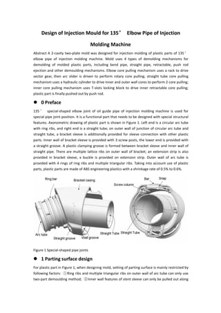
  • 1. Design of Injection Mould for 135° Elbow Pipe of Injection Molding Machine Abstract A 2-cavity two-plate mold was designed for injection molding of plastic parts of 135° elbow pipe of injection molding machine. Mold uses 4 types of demolding mechanisms for demolding of molded plastic parts, including bend pipe, straight pipe, retractable, push rod ejection and other demoulding mechanisms. Elbow core pulling mechanism uses a rack to drive sector gear, then arc slider is driven to perform rotary core pulling; straight tube core pulling mechanism uses a hydraulic cylinder to drive inner and outer wall cores to perform 2 core pulling; inner core pulling mechanism uses T-slots locking block to drive inner retractable core pulling; plastic part is finally pushed out by push rod.  0 Preface 135 ° special-shaped elbow joint of oil guide pipe of injection molding machine is used for special pipe joint position. It is a functional part that needs to be designed with special structural features. Axonometric drawing of plastic part is shown in Figure 1. Left end is a circular arc tube with ring ribs, and right end is a straight tube; on outer wall of junction of circular arc tube and straight tube, a bracket sleeve is additionally provided for sleeve connection with other plastic parts. Inner wall of bracket sleeve is provided with 3 screw posts, the lower end is provided with a straight groove. A plastic clamping groove is formed between bracket sleeve and inner wall of straight pipe. There are multiple lattice ribs on outer wall of bracket; an extension strip is also provided in bracket sleeve, a buckle is provided on extension strip. Outer wall of arc tube is provided with 4 rings of ring ribs and multiple triangular ribs. Taking into account use of plastic parts, plastic parts are made of ABS engineering plastics with a shrinkage rate of 0.5% to 0.6%. Figure 1 Special-shaped pipe joints  1 Parting surface design For plastic part in Figure 1, when designing mold, setting of parting surface is mainly restricted by following factors: ①Ring ribs and multiple triangular ribs on outer wall of arc tube can only use two-part demoulding method; ②Inner wall features of stent sleeve can only be pulled out along
  • 2. center line of bracket sleeve and center line of three screw columns, lattice ribs on outer wall of bracket sleeve can only be pulled out in vertical direction perpendicular to surface where lattice ribs are located. Demoulding of buckle feature can only be carried out in direction perpendicular to bottom surface of buckle; ③Demoulding of inner wall of arc tube can only be demoulded by core pulling of arc rotation; ④Inner wall of straight pipe feature needs to be core-pulled and demoulded, core-pulling direction can be set in same direction as inner wall of stent sleeve. From above analysis, it can be seen that plastic part to be molded can only be typed at PL shown in Figure 2 to facilitate demolding of molded plastic part, simplify demolding mechanism and mold structure. Under parting setting of PL surface, automatic demoulding of molded plastic part can be realized by setting only 3 slider mechanisms. Functions of corresponding three sliders are: ① Slider 1 is shaped with wall-clamping grooves, straight grooves, screw posts and formed tube features; ② Slider 2 is shaped with arc tube inner wall features; ③ Slider 3 is shaped with ribs and buckles feature. Ring rib and rest of outer wall of plastic part are formed and demolded by fixed mold insert and movable mold insert. Figure 2 Parting and demolding design  2 Forming part design In parting state shown in Figure 2, determined molded part design is shown in Figure 3. Slider 1 corresponds to a straight tube slide, slide 2 corresponds to an arc slide, and slide 3 corresponds to an inner core-pulling slide. Straight tube slide block drives core pulling through hydraulic mechanism, circular arc slide block drives rack through hydraulic mechanism, rack drives sector gear, and sector gear drives circular arc slide block through rotating shaft to implement rotating core pulling. Inner core-pulling slider integrates its driving and locking requirements, can be locked and driven by a T-slot locking block, inner core-pulling is implemented for corresponding features.
  • 3. Figure 3 Design of molded parts Considering production efficiency of plastic parts, layout of 2 cavities is adopted. In order to simplify mechanism and optimize mold structure, straight pipe sliders of 2 cavities in Figure 3 are driven by a common hydraulic mechanism, arc sliders in two cavities are also driven by a common rack and slider mechanism. Inner core-pulling sliders of two cavities also use common T-slot locking block for locking and driving. In design of gating system, in view of convenience of runner processing, a φ8 mm CNC milling cutter is used to process circular runner, considering structural space setting, reducing use size of mold base, and using oblique gate for sprue bushing.  3 Mold structure design  3.1 Dynamic and fixed mold design According to 2-cavity structure set on parting surface, corresponding movable and fixed mold structures are shown in Figure 4. Combining demolding mechanism and requirements of simplifying mold structure, a two-plate mold base is selected. In fixed mold setting, cavity plate adopts an eccentric arrangement to ensure that center of sprue sleeve is aligned with center of mold base. Overall cavity of mold is eccentrically poured to control injection pressure. Cavity plate insert is installed in fixed mold plate. Material is 2344 alloy steel and a single waterway is used for cooling.
  • 4. Figure 4 Dynamic and fixed mold structure In movable mold, 3 composite mechanisms are used to simultaneously perform core-pulling and demolding of two cavities. Corresponding mechanisms are straight tube core-pulling mechanism, elbow core-pulling mechanism and inner core-pulling mechanism. Final demolding of plastic part to be formed is carried out by pushing out with a push rod, core insert is installed on movable mold plate, material is P20, and a single waterway is also used for cooling.  3.2 Mold structure Mold structure is shown in Figure 5. Figure 5 Mold structure 1. Fixed mold base plate 2. Fixed template 3. Arc slider 4. Arc pressing bar 5. Limit screw 6. Rotating shaft 7. Connecting screw 8. Rotating shaft 9. Sector gear 10. Rack 11. Rack Slider 12. Spacer 13. Movable mold base 14. Pusher 15. Travel switch 16. Movable mold pad 17. Movable template 18. Limit glass beads 19. Inner core-pulling slider 20. T-shaped locking block 21. Core insert 22. Cavity plate insert 23. Diagonal sprue sleeve 24. Wall-clamping groove core 25. Straight pipe core 26. Straight pipe slider 27. Hydraulic cylinder 28. Reset rod 29. Reset rod Spring 30. Limit block 31. Support column 32. Push rod 33. Push plate guide column 34. Guide column 35.
  • 5. Hydraulic cylinder (1) Mold adopts a two-plate mold base, and a movable mold backing plate 16 is added under movable mold plate 17 to facilitate installation of elbow core-pulling mechanism. (2) In elbow core pulling mechanism assembly, core pulling assembly of a single cavity mainly includes parts 3~11. Piston rod of hydraulic cylinder 35 drives rack slider 11 to move, and rack slider 11 drives sector gear 9 to rotate around center of rotating shaft 8, rotating shaft 8 then drives arc slider 3 located in arc bead 4 on movable mold plate 17 to rotate, inner wall of circular arc tube of molded plastic part is rotated and cored. Position of circular arc slider 3 is restricted by limit screw 5. (3) Inner core pulling mechanism. Inner core pulling mechanism components mainly include parts 18 to 20. When mold is opened, inclined T-shaped grooves on both sides of T-shaped locking block 20 simultaneously drive two inner core-pulling sliders on both sides to implement inner core-pulling. Limits of two retracting core-pulling sliders are respectively limited by their respective limit glass beads 18. (4) Straight tube core pulling mechanism. Straight tube core pulling mechanism is a double core pulling mechanism, a delay core pulling is set between two core pullings, delay distance is 10 mm. Mechanism components include parts 24 to 27. In first core-pulling process, wall-clamping groove core 24 is first drawn out by 10 mm, then inner wall core of straight tube is drawn out. Both cores are driven by straight tube slider 26. Tube slider 26 is driven by piston rod of hydraulic cylinder 27. (5) Launch agency. Final demolding of plastic part is realized by pushing out a plurality of push rods 32, push rod 32 is pushed by push plate 14, push plate 14 is connected and driven by ejector rod of injection molding machine through connecting rod. In order to prevent push rod 32 from interfering with slider of straight tube core pulling mechanism and arc slider of elbow core pulling mechanism when resetting, push rod 32 must be retracted to its position before resetting. Therefore, push plate 14 is equipped with a travel switch to detect its reset. Only after push plate 14 is reset, piston rods of hydraulic cylinders 27 and 35 can act to drive sliders on respective mechanisms to reset.  3.3 Mold work process When mold is working, operating principle of mechanism is as follows. (1) Piston rod of hydraulic cylinder is core-pulled first. Before mold is opened, because hydraulic cylinders 27 and 35 are in series, piston rod of hydraulic cylinder 35 moves first to complete core pulling of inner wall of elbow, then piston rod of hydraulic cylinder 27 moves to complete core pulling of wall groove and inner wall of straight pipe. . (2) Mold has only a single parting surface. When mold is opened after injection, sliding block of injection molding machine drives movable mold to move, mold opens at parting surface. (3) Launch. After mold is opened, movable mold continues to move, ejector rod of injection molding machine drives push plate 14, push plate 14 pushes push rod to push plastic part out of core insert 21 to realize demolding of plastic part. (4) Reset. When resetting, ejection mechanism is reset first, reset detection is performed by travel switch 15, piston rods of hydraulic cylinders 27 and 35 are sequentially controlled to drive parts to reset.  4 Conclusion
  • 6. Combined with structure of plastic part, a 2-cavity two-platen injection mold was designed. Single-point side gate was used for pouring, main runner uses inclined gate bushings to supply materials, which optimizes mold structure. In order to realize automatic demoulding of plastic parts, 4 kinds of demoulding mechanisms are used to assist demoulding, namely, bend tube core pulling mechanism, straight tube core pulling mechanism, internal retractable core pulling mechanism, and push rod ejecting demoulding mechanism. Mold structure design utilizes mold base structure space and saves material costs.