Carbon Stock Assessment in Banten Province and Demak, Central Java, Indonesia
Zhang1996 galvanic corrosion of zn
1. REVIEW'
Galvanic Corrosion of Zinc and Its Alloys
X. G. Zhang*
COMINCO Product Technology Centre, Sheridan Park, Mississauga, Ontario, Canada L5K 184
ABSTRACT
Theoretical and practical information on galvanic corrosion of zinc and its alloys, coupled to other metals, particu-
larly steel, is organized and presented, along with a conceptual and elemental analysis of galvanic coupling between zinc
and steel. Various factors which may play roles in galvanic action between zinc and coupled metals are systematically dis-
cussed. The principles and practical applications of galvanic protection for steel by zinc coatings, zinc anodes, zinc-rich
paints, and other means are also reviewed. Galvanic corrosion of zinc as well as galvanic corrosion of steel are essential-
ly determined by chemical and electrochemical processes in the system, which is a function of the electrode potentials,
reactions involved, metallurgical properties, of the materials, surface conditions, electrolytic properties, and geometric
arrangement.
Introduction
The most important commercial application of zinc and
its alloys is for the protection of steel. Through galvaniz-
ing, metal spraying, sacrificial anodes, zinc-dust paints,
and other methods, zinc-protected steels are widely used
in automobiles, building structures, reinforced concrete,
roofing, and other domestic and industrial structures. In
the case of zinc-coated steel, i.e., galvanized steel, the pro-
tection is mainly due to the much better corrosion resist-
ance of zinc since, in most natural environments, zinc cor-
rodes by a factor of 5 to 100 times slower than steel.1'2
Extra protection is provided, at places where the coating
is damaged and the steel is exposed, by galvanic action
between the zinc coating and the substrate steel.
Galvanic corrosion is particularly important for appli-
cations of zinc and its alloys, whether as a coating, an
anode, or a zinc-dust paint. In most situations, unlike
many other metals, galvanic corrosion of zinc is desirable
because it is required for protecting another metal, usual-
ly steel. The unique role of zinc in galvanic protection is
mainly owing to its low position in the galvanic series.
Also, because of its relatively low self-corrosion rate and
lack of full passivation in many common environments, it
has a high current efficiency in many situations as sacrifi-
cial anode for galvanic protection of steel structures.'2°
The galvanic corrosion of zinc has been the subject of
maoy investigations. As shown in Table I, various factors
have been studied on the galvanic action between zinc
and other common metals and alloys. However, there has
been little effort to systematically organize the informa-
tion generated in these studies. It is the objective of this
paper to systematically summarize theoretical and exper-
imental information concerning the effect of various fac-
tors on the galvanic corrosion of zinc and its alloys as well
as on the galvanic protection of steels. A conceptual and
elemental analysis is also made for the galvanic action
between zinc and steel for geometries of particular impor-
tance to applications.
Factors in Galvanic Corrosion
When two dissimilar metals in electrical contact with
each other are exposed to an electrolyte, a current, which
is called a galvanic current, flows from one to the other.
Electrochemical Society Active Member
Galvanic corrosion is that part of the corrosion which
occurs to the anodic member of such a couple and is
directly related to the galvanic current by Faraday's law.3
Under a galvanic corrosion condition, the simultaneous
additional corrosion taking place on the anode of the cou-
ple is called the local corrosion. The local corrosion may or
may not equal the corrosion, called the normal corrosion,
taking place when the two metals are not electrically con-
nected. The difference between the local corrosion and the
normal corrosion is called the difference effect which may
be positive if the local corrosion decreases when galvanic
current flows, or negative. A galvanic current generally
causes a reduction in the total rate of corrosion of the
cathodic member of the couple. In this case the cathodic
member is cathodically protected.42
The polarity and direction of galvanic current flow
between two connected bare metals is determined by the
thermodynamic reversible potentials of the metals. The
metal which has a higher reversible potential in the elec-
tromotive force (EMF) series is the cathode in the galvan-
ic couple. In real situations owing to the formation of a
surface oxide or a salt film on the surface, or owing to dif-
ferences in the local electrolytes around the two coupled
metals, the polarity may be different from that predicted
by the electromotive series.
Compared to normal corrosion, galvanic corrosion is
generally more complex owing to the fact that, in addition
to materials and environmental factors, it involves also
geometrical factors. The fundamental relationship in gal-
vanic corrosion is described by Kirchhoff's Second Law
EeEaIRe+IR,,, [11
where R, is the resistance of the electrolytic portion of the
galvanic circuit, Rm the resistance of the.metallic portion,
E the effective (polarized) potential of the cathodic mem-
ber of the couple, and Ea the effective (polarized) potential
of the anodic member Generally, Rm is very small and can
be neglected. Ea and F, are functions of the galvanic cur-
rent I; hence, the potential difference between the two
metals, when there is a current flow through the elec-
trolyte, does not equal the open-circuit cell potential.
In addition to the potential difference between the two
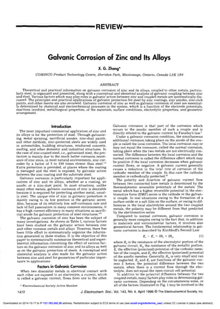
coupled metals, many factors play roles in determining gal-
vanic corrosion. Depending on the circumstances some, or
all of the factors illustrated in Fig. 1 may be involved in the
1472 J. Electrochem. Soc., Vol. 143, No. 4, April 1996 The Electrochernical Society, Inc.
) unless CC License in place (see abstract).ecsdl.org/site/terms_useaddress. Redistribution subject to ECS terms of use (see131.193.242.26Downloaded on 2014-10-17 to IP
2. Alloy
Al
Al alloys
Al alloys
Cu
Cu
Cu
Cu
Cu-Ni alloy
Cu, brass
Fe
Fe
Steel
Steel
Steel
Steel
Steel
Steel
Steel
Steel
Steel
Steel
Steel
Steel
Steel
Steel
Steel
Steel
Steel
Steel
Stainless steela
Stainless steelr
Passive zinc
Pb,Fe
Cd, Cu, Ni
Sn, stainless steel
Ti-6Al-4V
Al, Cu, Pd, Fe
Cu, Pd, Ni, Mg,
AmAl, Sn, Cr,
Steel, stainless steel
Carbon-filled polyethylene
Electrolyte
3.5% NaC1
3.5% NaC1
0.6 N NaCl
Humid gas
0.1 NNaC1
0.01 MNaC1
5% NaC1
Seawater
0.1 M Na2SO4,
XCI, KNO3
Seawater
3% NaC1
CO, SO2, NO2
In hot water
Hot tap water
Concrete
pH 3.8 to 9.5
0.05 1W t'{a2CO3
3.5% NaCl
0.1 M NaCl
1 N NaC1
0.6 NNaC1
Painted
Slmthetic seawater
NaC1, MgSO4, etc.
5% NaCI
Seawater
Soils
3% NaC1
0.01 M Na2SO4
0.001 M Na2SO4
Soils
0.01 NNaC1
0.1 MK,Cr04
Soils
Measurements
g,b Ig
E,I
E, I distribution
E distribution
E ,
E5ditribution
E distribution, I
E distribution
I, impedance
Eg, I
Eg, t
E,ej
I pH
*eight loss, E-I
E ,1
lforphology
Transient E-t
Weight loss
*eight loss
E,
E, I distribution
E, I distribution
ñ?drop
E , I, Weight loss
loss
Effect studied
Area effect
Al vs. alloys
Ni alloying
Kelvin probe
Effect of R
Modeling
Equipment
Cathodic protection
Corrosion rate
modeling
Zn-rich coating
pf reversal
P reversal
Cathodic protection
Galvanic E-I curve
P reversal
Corrosion products
Variation of pH
Galvanic protection
Ni alloying
Paint adhesion
Surface property
Solution effect
Effect of paint
Flow rate
Galvanic protection
SCC of steel
Thin electrolyte
Protection power
Effect of soil R
Area effect
Pitting
Er - E,
Corrosion rate
Corrosion rate
Area effect
Ref.
97
4
107
5
6
7
8
9
10
11
12, 13
14, 15
16, 11, 18
19
20
21
22
23, 24
25
108
27
29
30
so
32
33
34
35
36
37
38
39
40
41
54, 55
38
Galvanic current.
Potential of couple.
Potential of cathode.
Potential of anode.
Stainless steel.
Potential reversal.
galvanic corrosion, Generally, for a given couple, the fac-
tors in categories (a), (b), and (c) vary less from one situa-
tion to another than the factors in categories (d), (e), and (f).
The effect of the geometric factors on the galvanic actions
could, in many cases, be mathematically analyzed. On the
other hand, the effect of the factors related with electrode
surface condition and its effect on the reaction kinetics in
real situations can be very difficult to determine. (The sys-
tematic and detailed information on each of these factors
can be found in Corrosion and Electrochemistry of Zirtc.'20)
(a) Reversible el.cwde
petenaJs
(i') Reacti.n.s
zinc d*aaelukn
02 tluctien
hydrsen ev&uk•n
(C) Metallurgical facters
all.yuig
heat keatment
mschaiucal w.rking
(d) Surface csndions
surface catmenL
pastwt film
- cry*sl*n pr.ducts
(f) G.ometnc facters
area ,f zinc and Steel
distance between z.inc and steel
lecati.n
share and .nentauon
V
(e) Electrolyte preperues
ionic species
pH
conductivity
temperature
velume
flew rate
Fig. 1. Factors involved in.gal-
vanic corrosion of a zinc/steel
couple.
J. Elect rochem. Soc., Vol. 143, No. 4, April 1996 The Electrochemical Society, Inc. 1473
Table I. Studies on the galvanic corrosion of zinc coupled to different metal alloys in various eleclcolytes.
3.5% NaC1
Atmospheres
0.1 NNaC1
V
) unless CC License in place (see abstract).ecsdl.org/site/terms_useaddress. Redistribution subject to ECS terms of use (see131.193.242.26Downloaded on 2014-10-17 to IP
3. 1474 J. Electrochern. Soc., Vol. 143, No.4, April 1996 The Electrochemical Society, Inc.
Fig. 2. (a) General geometry of
a zinc/steel galvanic couple; (b)
geometry of zinc coated steel;
and (c) geometry of a zinc anode
coupled to a steel cathode.
L I. t't Ijzinc sleet
_______ —
I I w—
d o
electrolytt
d-__J'
Id
Analysis
The mathematical description of galvanic corrosion can
be very complex because of the many factors involved. It
can, however, be simplified for the galvanic corrosion of
zinc. In real applications, galvanic corrosion of zinc occurs
mainly in two situations: when it is used as a coating and
when it is used as a sacrificial anode. The specific geome-
tries involved in these applications may be generalized by
the scheme illustrated in Fig. 2a. When the distance
between zinc and steel, d, equals zero, it represents the
case of galvanized steel on which zinc coating is partially
removed as shown in Fig. 2b. On the other hand, the case
when d >> (Xagd), d >> Xce (the lengths of zinc and steel
electrodes) can be considered as that when the zinc is used
as a sacrificial anode as shown in Fig- 2c.
The basic relationships for the geometrical arrangement
shown in Fig. 2a can be expressed in the following
Ia=Ie [2]
B, — Ba = hlaV) —
,(x") + AVR(xa, x') Xa 0 [3]
X' 0
where B and B, are the corrosion potentials of zinc and
steel under separate open-circuit conditions, respectively;
ha and 'q, the anodic and cathodic overpotentials under
coupled condition; and AVR the ohmic potential drop
across the electrolyte between at on the zinc surface and at
on the steel surface. ' is the total anodic current and 4the
total cathodic current
Ia = Jd j(f)ja [4]
4 = ie(x')idx' [5]
in which 1 is the width of the electrodes and ia(at) and ijx')
the respective current densities on the anode and cathode.
Assuming both the anodic and cathodic reactions are acti-
vation controlled, they can be expressed by the Butler-
Volmer equation8 -
= iO [exp [Paaha(at)] — exp ['i3aeTIa(t)]1
= io,O, {exp [13,a'fle(X')] — exp [— ,,ii,(x')]}
in which 10a and i0, are the exchange currents for the anod-
ic and cathodic reactions, respectively, I3aa' Pa,, Pea, and I,,
the kinetic constants, and °a and 9, the area factors vary-
ing between 0 and L 9 equals 1 when the whole surface is
active and 9 is close to zero, if the surface is fully passi-
vated. In the cases where the cathodic reaction is limited
by oxygen diffusion in the electrolyte, Eq. 7 is replaced by
= 4FD0C02/S [8]
where F is the Faraday constant; D0, the diffusion coeffi-
cient of oxygen in the electrolyte; C02, the oxygen concen-
tration in the bulk; and 5, the thickness of the diffusion
layer.
The total ohmic potential drop in the electrolyte
between any two points on the surface of the anode and
the cathode for the situation in Fig. 2a consists of three
parts
AVR(f, Xe) = AVa(X') + MT,(x') 4-'A%76 [9]
where Va, LV,, and AT/ represent the ohmic potential drop
in the electrolyte in the x direction across the anode, across
the cathode, and across the distance between the, anode and
cathode, respectively. They can be further expressed by
LVa(Xa) = Jj(at)ff(f) [10]
LV,(x') = J03e(a')u11(X) [11]
= TaRd = 4Rd [12]
where R = pd/ti with p the resistivity of the electrolyte, t
the electrolyte thickness, d the distance between the anode
and cathode, 1 the width of the electrodes, and 3,, and .,,
given by the following Eq- 13 and 14, are the sums of the
current from at to Xae on the anode and from X' to X,, on the
cathode, respectively
= Jaeiv)ldra [13]
3, = [141
It can be seen that the factors listed under categories (a),
(b), (c), (d), and (e) in Fig. 1, contributed to galvanic action
through affecting the electrochemical reaction kinetics
given by Eq. 6 and 7. For example, changing the pH of the
solution may cause a change of the kinetic parameters: ia,,,
joe, Pa' or ii,,; or it may cause a change of the effective area,
°a, or 9, through passivation. On the other hand, the
geometric factors under category (f) may affect the gal-
vanic corrosion through the parameters in all the equa-
tions from 4 to 14.
Equations 4 to 14 apply to a rather general geometry.
For a specific application they can be further simplified.
In the case of Fig. 2b representing the galvanic action on
zinc-coated steel where the bare steel surface is next to the
zinc-coated steel surface, the term AT/ in Eq. 9 becomes
zero. For the geometry in Fig. 2c, representing the situa-
tion of galvanic protection of steel by a zinc anode when
d >> (Xee — d), d >> X,,, 4 and 4 in Eq. 4 and 5 simply
become iaAa and j,A, with A, = i(Xae — d) and A, = iXee, the
areas for the anode and the cathode, respectively. In addi-
tion, LVa and LV, in Eq. 9 can be taken as zero because
they are very small compared to LVd. In such a case, the
geometry in the galvanic cell, i.e., shape and orientation of
electrodes, size of the electrode, etc., become insignificant
in determining the galvanic action of the couple, and the
galvanic corrosion of the anode, as well as the galvanic
protection of the cathode becomes uniform (over the anode
electrolyte
/.zinc coatag
(b)
Xt L
(a)
(c)
and
[61
[7]
) unless CC License in place (see abstract).ecsdl.org/site/terms_useaddress. Redistribution subject to ECS terms of use (see131.193.242.26Downloaded on 2014-10-17 to IP
4. .1 Electrochem. Soc., Vol. 143, No. 4, April 1996 The Electrochemical Society, Inc. 1475
..1
C
I-z*&3
I-a&
and cathode surfaces). Thus, the galvanic action can be
fully described by the polarization characteristics of the
anode and the electrolyte resistance. In this case, the rela-
tion between the effective potentials, galvanic current, and
resistance can be graphically represented by the anodic
and cathodic polarization curves as shown in Fig. 3.
When the solution resistance R is infinite, no current
flows and E, — Ea is the open-circuit value of the cell
potential. As R is made smaller, I increases, and E — F,,
becomes smaller because of polarization. When H is zero,
F, — F,, becomes zero and the galvanic current reaches the
maximum, known as the "limiting galvanic current," and
is at the intersection of the polarization curves of the
anode and cathode. The exact shapes of the anodic and
cathodic polarization curves depend on the electrochemi-
cal reaction kinetics of each metal in the electrolyte and
are thus functions of pH, temperature, solution concentra-
tion, diffusion, formation of passive films, etc. Normally,
the anodic dissolution of zinc is activation controlled with
a relatively small Tafel slope (around 40 mV). The
cathodic reactions on the steel surface, on the other hand,
can either be activation or diffusion-controlled depending
on the conditions, particularly solution pH and aeration
conditions. The typical shape of anodic polarization curve
for zinc, (EA), and cathodic curve, (F,,), for steel are illus-
trated in Fig. 3.
A galvanic-corrosion system may operate under differ-
ent control mechanisms. If the anode does not polarize and
the cathode does, then, in solutions of low resistivity, the
current flow will be controlled entirely by the cathodic
electrode. Such a situation is considered to be under
cathodic control. If the anode polarizes and the cathode
does not, the status is reversed and the system is said to be
under anodic control. If neither electrode polarizes and the
current flow is controlled by the resistivity of the path,
mostly in the electrolyte, then the system is said to be
under resistance control.
Potential and Current Disfribution
The galvanic corrosion of the anode and the galvanic
protection of the cathode are essentially governed by the
potential distribution across the surface of the electrode.
The galvanic current distribution can be determined from
the potential distribution when the potential-current rela-
tionships for the electrodes are known. The exact descrip-
tion of the potential and current distributions on the sur-
faces of a galvanic couple can be obtained by solving
Laplace's equation.
V2 E(x, y, z) = 0
There are a number of mathematical models using
Laplace's equation for galvanic systems with different cell
geometries.46-4851'52 In these models the polarization para-
meter; Li, is often used
L, = 1/p I d1jdI, I [16]
where p is the specific resistivity of the electrolyte, I is the
current density, and is the overpotential of the anode or
the cathode. The polarization parameter, defined origi-
nally by Wagner,49 has the dimension of length and pro-
vides an electrochemical yardstick for classifying electro-
chemical systems. Waber and other authors1146-48 used the
parameter to describe the behaviors of galvanic corrosion
cells. According to Waber,46 whether the anode and cath-
ode behave "microscopically" or "macroscopically" is
determined by the ratio of the dimension of either elec-
trode, C,, divided by the polarization parameter, L,. The
mathematical modeling indicated that, when the ratio,
C,/L1, is small, the variation of current density across an
electrode is small, i.e., the electrode behaves microscopi-
cally. On the other hand, when the characterizing ratio is
large, i.e., when the electrode dimension is much larger
than L,, the electrode process can be regarded as macro-
scopic, and the variation of current density across the
electrode surface is large.
McCafferty48 modeled the potential distribution of a
concentric circular galvanic corrosion cell assuming a lin-
ear polarization for both the anodic and the cathodic reac-
tions. Figures 4 and 5 show the calculated results on the
potential distribution and current distribution as a func-
tion of electrolyte thickness for a polarization parameter
of the anode L,, = 1 cm and the cathode L,, = 10 cm. It can
be seen that, in the bulk electrolyte, the potential variation
across the electrodes is small but both the anode and the
cathode are strongly polarized; the actual electrode poten-
tials are far away from F°,, and E. Under a thin electrolyte,
the potential variation is large from the anode to the cath-
ode but both the anode and cathode are only slightly
polarized except for the areas near the boundary between
the anode and the cathode. The galvanic current increases
with increasing electrolyte thickness. Also, the current is
distributed on the electrode surface more uniformly in
bulk solution than in thin layer solutions where the cur-
rent is more concentrated near the contact line in the thin
GALVANIC CURRENT
Fig. 3. Graphic estimation of galvanic current.
0.5
RADIUS. r(cm)
Fig. 4. Distribution of electrode potential for I = 1 cm and 4, =
10 cm far different electrolyte thicknesses. (Anode radius a =
[15] 0.5 cm, cathode radius c = 1.0 cm; E°0 = OV, E = 1 V). 46
) unless CC License in place (see abstract).ecsdl.org/site/terms_useaddress. Redistribution subject to ECS terms of use (see131.193.242.26Downloaded on 2014-10-17 to IP
5. 1476 J. Electrochem. Soc., Vol. 143, No.4, April 1996 The Electrochemical Societç Inc.
0
0
a _____________ _____________
UI
p, mV
—7011
-iou
-4110
3110
—2110
-f00
0
-790
•
I•
-u00'
•
-400•
•
-'loll.
-2110
• -llh1l
•
t/Q
Zn. I • .CtiI
7 111 20 30 0 ill 50
4p,mV
Zn, • I • ,Cuj
0 10 2030 40111 60
a
Specimen Length, mm
Zn, , ,Cu
RADIUS. r ian)
, mY
800
-700
100 ______________
u_ 1020J0401.76Z7
Specimen Length, mm
Fig. 6. Distribution of potentials on the electrode surface ofa gal-
vanic couple Cu-Zn in a 0.1 N NaCI solution. Electrolyte thickness:
1, 165 p.m. 2, 70 p.m, and 3, bulk electrolyte. Cited in Ref. 6.
two electrodes are far away.35 The fact that the galvanic
current is higher for thinner electrolytes, is opposite to the
prediction of the mathematical models.48'52 In these models
the rate of cathodic reaction on the cathode is assumed to
be independent of the electrolyte thickness. However,
under thin layer electrolytes, the oxygen diffusion rate is
increased since oxygen reduction is the main reaction on
the steel cathode. This change of the relative galvanic cur-
rent values for small and large distances, shown in Fig. 8,
is due to the change of the rate limiting process from oxy-
gen diffusion at a close distance to ohmic conduction in
the electrolyte at a large distance.35
The galvanic corrosion of zinc under thin layer elec-
trolytes measured experimentally for the couple illustrat-
ed in Fig. 7 are summarized in Fig. 935 The galvanic cur-
rent (1) increases with the area of steel (Wl) up to a certain
size, then decreases slightly with larger areas. It decreases
Fig. 5. Current distribution for different electrolyte thicknesses
under the some conditions as in Fig. 4•48
electrolyte. According to the calculation of Doig and
Flewitt51 the potential distribution is uniform in the thick-
ness direction under a thin layer electrolyte, e.g., 1 mm. It
is nonuniform when the cell is under a thick electrolyte.
Similar results were reported by Morris and Smyrl52 for a
galvanic cell with coplanar electrodes. The potential dis-
tribution of galvanic corrosion with more general geomet-
rical conditions is calculated by Munn and Devereux using
a finite element method.11'53
One problem in mathematical modeling is the assump-
tion that both the anode and the cathode have a linear or
Tafel polarization behavior over the entire potential range.
However, the polarization characteristics of a metal elec-
trode are generally different for the anode and for the
cathode, and they vary in different potential ranges.
Sometimes they also vary with the physical elements in
the galvanic cell such as electrolyte thickness. In addition,
the electrode properties of the coupled metals usually
change with time due to changes on the surfaces and in the
solution. These elements need to be taken into considera-
tion in using a mathematical model for predicting long-
term behavior in a real galvanic system.
The potential distribution on the electrode surface of a
galvanic couple can be experimentally determined.
Rozenfeld6 showed that the potential variation of the sur-
face of a coplanar zinc/copper couple greatly increases
with decreasing electrolyte thickness on top of the surface,
as shown in Fig. 6. The sharpest potential changes take
place on the copper cathode, while the anode does not
polarize at all. Zhang and Valeriote35 measured the poten-
tial and current distributions of a coplanar zinc/steel cou-
ple under thin layer electrolyte of various thicknesses and
salt concentrations using the cell design shown in Fig. 7.
The potential distribution on the zinc and steel are similar
to that measured on zinc/copper couple shown in Fig. 6.
Figure 8 shows that the galvanic current is larger for a
thinner electrolyte when the anode and the cathode shown
in Fig. 7 are close together, but it is the opposite when the
Zinc Steel
Fig. 7. A schematic representation of the electrochemicol cell used
for obtaining data on protection distance and galvanic corrosion
current; D, the distance between the zinc and the steel electrode; W,
width of the steel electrode; and X, the position on the steel elec-
trode35 Reprinted from: X. G. Zhang and E. M. Valeriote, Corros.
Sci, 34, 1957 (1993) with the kind permission from Elsevier Science
Ltd., The Boulevard, Langford Lane, Kidlington 0X5 1GB, UK.
) unless CC License in place (see abstract).ecsdl.org/site/terms_useaddress. Redistribution subject to ECS terms of use (see131.193.242.26Downloaded on 2014-10-17 to IP
6. J. Electrochem. Soc., Vol. 143, No. 4, April 1996 The Electrochemical Society, Inc. 1477
Fig. 8. The galvanic current as a function of the distance between
the zinc and the steel in 0.001 M Na2504 solution of different elec-
trolyte thicknesses, t, for a steel width of 1 mm. Reprinted from:
X. G. Zhang and E. M. Valeriote, Corros. Sd., 34, 1957 (1994) with
the kind permission from Elsevier Science Ltd., The Boulevard,
Lanford Lane, Kidlington 0X5 1GB, UK.
sharply as the distance between zinc and steel (0) increas-
es because the system becomes ohmically- resistance con-
trolled. It is relatively less sensitive to the variation of
electrolyte layer thickness (t). The width of zinc has little
effect on the galvanic current because most anodic reac-
tions take place at a very narrow area at the edge closest
to the steel.
Effect of Coupled Metals
Different alloys have different electrode potentials.
However, the extent of the galvanic corrosion of a metal
does not always follow the potential difference between
the coupled metal alloys. Thble II shows that, although
the potential difference between steel and zinc is much
less than that between stainless steel and zinc and
between Ti-6Al-4V and zinc, the amount of galvanic cor-
rosion is much larger in the zinc/steel couple than in the
other two couples.41
This indicates that the difference in corrosion potentials
for uncoupled metals is not a reliable indicator of the
extent of galvanic corrosion. Similar results have been
reported on the galvanic corrosion of zinc when coupled to
various metal alloys in different atmospheres.54 As shown
in Table V, the amount of corrosion is more when zinc is
coupled to mild steel than to copper, although the poten-
tial difference between zinc and steel is smaller than that
between zinc and copper. In these situations, other factors,
such as reaction kinetics and formation of corrosion prod-
ucts, rather than just the potential difference between the
two metals, are the rate determining factors in the galvan-
ic corrosion. The different galvanic corrosion rates of the
anodes coupled with different cathode materials, when the
cathodic reaction is oxygen-diffusion limited, can be
explained by the different diffusion rates of oxygen
through the oxide films. On the other hand, when diffusion
is not the limiting process, the variation in galvanic
corrosion rate can only be due to the cathodic efficiency
for oxygen reduction in the oxide scale on the cathode
surf ace.4'
As a result of the galvanic corrosion of the anodic metal
the corrosion of the coupled metal or alloy is generally
reduced, that is, cathodically protected. The extent of pro-
tection for different metal alloys galvanically coupled to
(c)
1.4 mm
Fig. 9. Three-dimensional plots
of the galvanic corrosion current
of zinc in 0.001 M Na2SO4 solu-
tion for different distances ID)
between the zinc and the steeL
Reprinted from: X. G. Zhong and
E. M. Valenote, Corros. Sc,, 34,
1957 (1993) with the kind per-
mission from Elsevier Science
Ltd., The Boulevard, Lanford
Lane, Kidlington 0X5 1GB, UK.
Table II. Galvanic corrosion rate of zinc (20 cml
coupled to various alloys of equal size tested in
33% NaCI solution for 24 h. "
Coupled rw,b AV
alloy (m/y) (m/y) (mV)
0
0 0.5 1 1.5 2 2.5 3 3.5 4 4.5
DIstance 1cm)
Zn
SS 304
Ni
Cu
Ti-6A1-4V
Sn
4130 steel
Ccl
244
990
1065
315
320
1060
600
101
705
1390
1450
815
810
1550
660
0
905
817
811
729
435
483
258
Measured as galvanic current.
Measured as weight loss.C
Potential difference between zinc and the coupled metal
before testing.
Used with permission. F Mansfeld and J. Kenkel, Corroswm,
3t, 298 (1975).
I
D = 0.05mm
120 A
I
120 gA
D = S mn
w
14mm
(a) I
(b)
D =40mm 120 1jA
t
) unless CC License in place (see abstract).ecsdl.org/site/terms_useaddress. Redistribution subject to ECS terms of use (see131.193.242.26Downloaded on 2014-10-17 to IP
7. 1478 J Electrochem. Soc., Vol. 143, No.4, April 1996 The Electrochemical Society, Inc.
zinc has been investigated in atmospheres,5455 in sea-
water93 and in soils.3337 The galvanic corrosion of zinc is,
however, not always beneficial to the coupled metal. It was
reported that, although zinc is anodic to aluminum, the
amount of aluminum corrosion in 3.5% NaCl solution is
increased when coupled to zinc, compared to the uncou-
pled condition.97 Similar results were reported by
Mansfeld et at.4 for a zinc/aluminum alloy couple in 3.5%
NaC1 solution. The higher dissolution rate of the coupled
Al alloy compared to the uncoupled one is attributed to
increased alkalinity on the surface of the Al alloy due to
the cathodic reaction.
As can be noted in Table II, the weight loss of zinc when
galvanically coupled to other metal alloys can be much
larger than the sum of the galvanic corrosion calculated
from the faradaic current plus the normal corrosion meas-
ured in a noncoupled condition. This implies that self-cor-
rosion (or the local corrosion) of zinc is enhanced by gal-
vanic coupling to another alloy.
Effect of Alloying
The addition of alloying elements in zinc changes its
electrochemical properties, such as electrode potential,
dissolution kinetics, oxygen and hydrogen reduction over-
potentials, and formation of solid surface films.12' Since
zinc is widely used in applications in which the galvanic
protection of steel is an essential requirement, alloying is
usually engineered to improve the normal corrosion resist-
ance but not to reduce much of the electrode potential dif-
ference between zinc and steel. In general, additions of
small amounts of alloying elements change the corrosion
potential of zinc little. With additions of alloying element
to about 10%, the potential of the zinc alloy may change by
50 to 100 mV, usually to a more noble value than the corro-
sion potential of zinc, as shown in Table III. For alloys with
more noble elements like Cu, Ni, and Fe the potential can
be much more positive when the concentration is high. For
example, Baldwin et at.'°7" found that Zn-Ni alloys gal-
vanically corrode in 0.6 N NaC1 solution when coupled to
aluminum alloys or steel up to about 14% Ni concentra-
tion, above which the polarity reverses and the corrosion of
the coupled aluminum alloys or steel are accelerated.
The corrosion potential of an alloy in an electrolyte is a
function of time. It tends to change to more positive values
with the time of immersion because, in most cases, the
preferential dissolution of zinc causes an enrichment of
the more noble elements on the surface. The polarization
behavior of zinc can also be significantly affected by alloy-
ing. High polarization resistance is often not desirable for
zinc when used for galvanic protection of steel because a
large polarization of the zinc anode reduces the amount of
current available for the polarization of steel.
Effect of Area
The effect of the anode and cathode areas on the gal-
vanic corrosion depends on the type of control over the
system. If the galvanic system is under cathodic control,
Steel NaC1, Na2SO4 —0.55 to —0.65 35,56,57
Zinc NaC1, Na,SO, —1.00 to —1.10 35,43,58,120
5% Al 3% NaC1 —1.04/—1.07 56,59
55% Al 1 NNaCI —0.99/—lOS 56,60
10% Fe 0.1 MNaC1 —0.97/—0.95 57,61
25% Fe 0.1 MNaC1 —0.95 57
50% Fe 0.1 M NaC1 —0.72 57
25% Mn 3% NaC1 —1.05 62
10% Cr 5% NaC1 —0.95 61
10% Ti 5% NaCi —1.00 61
10% Mg
10% Ni
5% NaCI
5% NaC1
—1.10
—0.90/—100
61
94,61
20% Ni 3.5% NaC1 —0.7 63
10% Cu 3.5% NaCI —0.85/—1.02 63,61
40% Cu 3.5% NaC1 —0.4 63
10% Co 5% NaC1 —1.02 94
variation in the area of anode will change the total amount
of corrosion little but variation of the cathodic area will. It
is the opposite if the system is under anodic control. The
total amount of corrosion will change by an area variation
of both electrodes if the system is under mixed control.
When it is primarily under resistance control the corrosion
will only change with electrode area if the resistance of the
electrolyte changes also with the areas of electrodes.
Pryor and Keir23 studied the effect of areas of zinc and
iron on the galvanic corrosion of zinc in 1 M NaC1 aerated
solution. Figure 10 shows that the galvanic corrosion of
zinc increases with increasing iron cathode area. On the
other hand, the galvanic corrosion of zinc changes only
very slightly with increasing zinc anode area. The results
indicate that the galvanic corrosion of zinc is mainly
cathodically controlled. This is confirmed by the polariza-
tion curves of the zinc iron couple shown in Fig. 11. The
shape of the curves suggests that variation of the iron area
will significantly change the galvanic current but varia-
tion of the zinc area will change the current only slightly
The effect of area varies from situation to situation. It
has been found that the polarity of the zinc/steel couple in
hot water reversed faster for a larger steel to zinc area
ratio.'8 Schick3' found that galvanized steel, coupled to
301 stainless steel in a solution containing 266 mg/liter CF
and 70 mg/liter SO;2 is controlled by both anode and cath-
ode areas. Mansfeld and Kenkel'7 found that, for the Zn/Al
couple in 3.5% NaC1 solution, the galvanic current densi-
ty changed little with the variation of both the zinc anode
area and the aluminum cathode area, largely owing to the
inactive surface of the aluminum.
Effect of Solution Factors
In aqueous solution, zinc is normally anodic to most
other common metal alloys and corrodes galvanically.
However, in some solutions in which passivation occurs,
zinc can be cathodic to other metal alloys due to the high-
er corrosion potential of the passive surface. Table IV
shows the corrosion loss of zinc and steel in coupled and
uncoupled conditions in various solutions.3' In all the solu-
tions, the galvanic action results in a protection of the
steel but the amount of zinc corrosion varies with the com-
position of the solution. The difference in the corrosion
— Weight loss
-- - No. of couloinbs
Fig. 10. Effect of area of mild steel cathode on the weight loss of
Zn anode (of area 100 cm9 and on the number of coulombs flow-
ing between the Zn-steel couple over a 96 h period in 1 N NoCl
solution at 25°C. 25
Alloy
Table Ill. Corrosion potential of zinc alloys in solutions.
U
In
In
0
4)
0'--4
0,Solution F,,, (V) Ref.
In
a
0-.4
:3
0
U
4-4
0
'4
0,
a
:3
C
area of steel cathode, cm2
) unless CC License in place (see abstract).ecsdl.org/site/terms_useaddress. Redistribution subject to ECS terms of use (see131.193.242.26Downloaded on 2014-10-17 to IP
8. J. Electrochem. Soc., Vol. 143, No. 4, April 1996 The Electrochemical Society, Inc. 1479
rates in magnesium sulfate and sodium sulfate indicates
the significant effect of cations on the reaction kinetics.
The presence of metal ionic species more noble than zinc,
such as Cu2 in solution, are known to enhance the corro-
sion of zinc due to the minigalvanic cells between zinc and
the copper islands deposited on the zinc surface.96
In the case where there is only a limited amount of elec-
trolyte, the composition of the electrolyte may change as a
result of the galvanic action. Massinon and Dauchelle
found23'24 an increase of pH at a confined electrolyte after
a certain time of galvanic action for a zinc/steel couple.
Pryor and Keir25 pointed out, that when the distance
between the anode and cathode is small compared to the
dimension of the electrodes, the galvanic corrosion is small
due to the limitation in the mass transport of the reactants
and reaction products.
The position of a galvanic couple in the solution can also
affect the galvanic actions between the coupled metals.
Shams et al.'° found there is a larger potential variation
near the solution surface between a zinc anode and a cop-
per cathode, which are half-immersed in the solution, due
to the higher oxygen concentration near the surface than
in the bulk solution.
Effect of Surface Condition
Formation of a surface film, whether a salt film or an
oxide film, may significantly change the properties of the
surface.'2° It may not only affect the rate of galvanic cor-
rosion, but also affect the polarity of the galvanic couple.
Usually, in low pH solution, zinc corrodes without the for-
mation of solid corrosion products on the surface. The cor-
rosion products formed in neutral and slightly basic solu-
tions are oxide and hydroxides, usually only loosely
attached to the surface.99"°°"2° The corrosion products
Table IV. Corrosion rate of equal area zinc-steel couples in
various solutionso (mpy).3°
Uncoupled Coupled
Solution Zinc Steel Zinc Steel
0.05 M MgSO4 + 2.6 3.4
0.05 M Na2SO4 11.2 10 33
0.05 NaC1 10 10 30
0.005 M NaCl 4.4 7 8.6
Carbonic acid 0.4 2.9 1.5
Calcium carbonate + 5.9 +
Tap water + 2.8 +
Specimen of equal area partially immers
signs indicate specimens gained weight.
ed for 39 days. Plus
formed on the zinc surface, in the pH range between 9 and
13, have varying degrees of compactness and can result in
passivation of the zinc surface'°"°2 The presence of certain
ionic species, such as carbonate, phosphate, and chromate
can enhance the formation of a passive film in a broader
pH range.'°3 As a result of passivation, the potential of zinc
can shift to more positive values and, thus, change its gal-
vanic behavior when coupled to another metal. Typically,
for example, if a stable and compact zinc oxide is formed,
the zinc electrode may show a potential more noble than -
0.5 V,. This potential is considered to be related to the
semiconducting properties of zinc oxide. Because zinc
oxide is an n-type semiconductor and has a flatband
potential of between —0.4 and —0.6 Ve,26'64'65 at equilibri-
um a positive overpotential is required to balance the
charge accumulation at the solid/electrolyte interface.
In certain cases, when the formation of a surface film is
not complete, a part of the zinc surface is passivated and
acts as the cathode to form a local galvanic cell, causing an
enhanced corrosion of the rest of the nonpassivated zinc
surface.66 Shames et at.39 found that galvanic current is
developed between a passivated zinc sample and a par-
tially passivated sample positioned in a cell of two com-
partments, containing 0.1 M K2CrO4 in one and 0.1 M
K2CrO4 and some NaCl in the other, respectively. Pits were
found to generate as a result of such a corrosion situation.
The galvanic action can vary also with the surface con-
dition of the metals coupled to zinc. Different kinds of sur-
face films can form on the metals to change the surface
condition. For example, aluminum has a low reversible
electrode potential but is usually cathodic to zinc in neu-
tral or acidic solutions, due to the formation of a passive
aluminum oxide film. Formation of iron oxide of the form
Fe203 may not change the iron corrosion potential much
but may change the electrode behavior of iron because
Fe203, like ZnO, is an n-type semiconductor which facili-
tates the cathodic reaction but hinders the anodic
Jordan22'68 studied the effect of corrosion products of
zinc and steel on the galvanic corrosion rate of zinc. He
found that the galvanic corrosion rate is dependent on the
behavior of the corrosion products on the steel. According
to Stratman and Muller,95 oxygen reduction on an iron
electrode is greatly increased due to the formation of the
rust because oxygen can be reduced in the iron oxide scale
which has a much larger effective surface area.
Polarity Reversal
The polarity of a zinc/steel galvanic couple may reverse
under certain conditions. Since Schikorr'6 first reported
the phenomenon of polarity reversal of galvanized steel in
hot water, many studies have been made to determine the
different conditions for polarity reversal to occur in hot
water and diluted solutions.'5'17'2' The change in the zinc
electrode potential is generally found to be responsible for
the reversal of polarity. Polarity reversal does not occur in
distilled water up to 65°C. Furthermore, without the pres-
ence of oxygen, it does not occur in hot water.'7'71'69
Many factors, such as temperature, solution composi-
tion, duration, pH, and the zinc to steel area ratio, have
been found to affect the occurrence and the time for polar-
ity reversal. In distilled water, polarity reversal of the
zinc/steel couple does not always occur at high tempera-
tures.'7 The presence of certain ionic species is often
responsible for the reversal to occur. Hoxeng and Prutton'4
investigated several chemical species in hot water in the
presence of oxygen and found that sulfates and chlorides
decrease, whereas bicarbonates and nitrates increase the
probability of reversal. In the absence of oxygen, zinc is
+ always found to be anodic to the steel. In a later paper
+ Hoxeng98 reported that the addition of even small amounts
(up to 20 ppm) of calcium salts or silicates can also
+ decrease the probability of reversals.
The pH of the solutions in which reversal occurs is usual-
ly slightly basic. Hoxeng and Prutten'4 evaluated the effect
of pH on the zinc potential in solutions of constant bicar-
III-
0
-s
4
I-
zw
I.-
0
Fig. 11. Effect of area of steel cathode on the polarization curves
for the Zn-steel couple in 1 N NaCI using 100 cm2 of zinc.25
CUflRNT (MICROAMPS)
) unless CC License in place (see abstract).ecsdl.org/site/terms_useaddress. Redistribution subject to ECS terms of use (see131.193.242.26Downloaded on 2014-10-17 to IP
9. 1480 1 Electrocherri. Soc., Vol. 143, No. 4, April 1996 The Electrochemical Society, Inc.
bonate ion concentration and found that, at about 6 0°C, the
most noble potential was reached in the pH range between
7 and 8, but the overall variation was not large.
The mechanisms of polarity reversal of a zinc/steel cou-
ple in hot water and solutions have been investigated by a
number of authors.157375 It is generally concluded that
polarity reversal observed in hot water and solutions is
primarily due to the ennoblement of the zinc, because the
potential of the steel is relatively little affected by changes
in the temperature. The generalities are (i) ennoblement of
zinc only occurs in certain waters and solutions. It occurs
readily in the presence of bicarbonate and less readily, or
not at all, in the presence of chloride or sulfate. (ii) The
presence of oxygen is necessary for the ennoblement. (iii)
For a given solution, the tendency for ennoblement
increases with increasing temperature.
Atmospheric Environments
Field exposure data are valuable for a realistic evalua-
tion of the relative severity of galvanic corrosion.
Compared to other types of corrosion, galvanic corrosion
in the field has not been well investigated. This is proba-
bly due to the more complicated situation; besides all the
factors which may affect the normal corrosion of a metal,
others, such as the kind of cathodic materials, the size of
the electrodes, anode and cathode arrangement, etc., are
also involved in a galvanic corrosion system. In addition,
this complexity makes application of the field corrosion
data limited because in a real situation it is not often that
the whole arrangement, of material, dimensional, and geo-
metric, plus the environmental factors, is closely similar to
that of an earlier field test.
A test program of galvanic corrosion in atmospheres was
started as early as 1931 by the American Society for
Testing Materials (ASTM).54 Since then a number of exten-
sive exposure programs, most of which took zinc as one of
the metals for the galvanic corrosion couples, have been
carried out all over the world.55'76'77'75 In general, galvanic
corrosion under atmospheric environments are evaluated
by weight-loss measurement. Unlike other environments
where the potentials and/or the galvanic current of the
two coupled metals can be measured, it is very difficult to
measure the in situ potentials of the metals under atmos-
pheric conditions.
For weight-loss measurement, two types of assembly
have been mostly used: plate type and wire-on-bolt type.54
In the plate type of assembly, a strip of one metal is
attached by bolts to a panel of another metal. The bolts are
insulated from the strip and panel. The galvanic corrosion
is evaluated by visual examination or by weight-loss
measurement for the strip or panel. In the wire-on-bolt
type of assembly, a wire of the metal to be tested is tightly
wound in the threads of a bolt of the other metal in the
couple. The galvanic corrosion is quantitatively estimated
by comparing the weight loss of the coupled wire to that
wound on the threads of a plastic bolt.
Galvanic corrosion of galvanized steel occurs at areas
where the coating is damaged and the steel underneath is
exposed, such as at cuts or at scratches. At these areas, the
exposed steel is cathodically protected while the sur-
rounding zinc coating is galvanically corroded. However,
in most cases for galvanized steel, the amount of coating
loss due to galvanic corrosion, compared to normal corro-
sion, is small because the exposed areas of bare steel are
usually too small to cause significant corrosion of the rel-
atively much larger zinc surface area. As a result, the
atmospheric corrosion rate, including galvanic and normal
corrosion, of galvanized zinc coating is usually very simi-
lar to that of uncoupled zinc.
Galvanic corrosion can, however, be a significant con-
tributor to the total corrosion of zinc in atmospheres when
it is connected to other metals of similar size. Data in
Table V, reported by Kucera and Mattsson,54 show the gal-
vanic corrosion rate of zinc wires, when coupled to bolts of
various metals in different atmospheres. Depending on the
connected metal and the type of atmosphere, the galvanic
Table V. Galvanic corrosion rate of zinc coupled to other common
commercial metals in different atmospheres (pm/y)."
Coupled alloy Rural Urban Marine
Zinc freely exp.
Mild steel
0.5
3.0
2.4
3.3
1.3
3.9
Stainless steel 1.1 1.8 2.0
Copper
Lead
2.2
1.6
2.0
2.4
3.2
3.4
Nickel 1.5 1.9 2.8
Aluminum 0.4 1.1 1.1
Anod. aluminum 0.9 1.9 1.0
Tin LU 2.6 2.4
Chromium 0.7 1.4 1.9
Magnesium 0.02 0.04 1.1
corrosion can be as much as five times the normal corro-
sion of zinc in a rural atmosphere and three times that in
a marine atmosphere. It can be seen from Table V that the
amount of corrosion is not directly related to the differ-
ence between the reversible potentials of zinc and the cou-
pled metal. Among the metals, mild steel acts as the most
efficient cathodic material, largely owing to the volumi-
nous rust which can absorb pollutants and retain moisture
and thus give rise to an aggressive electrolyte of good
conductivity.
Table VI shows the galvanic corrosion of zinc and iron in
four different atmospheres using metal disks clamped
together with insulating washers.5° In this galvanic cell,
the corrosion rate of zinc disk samples is increased by a
factor of 1.7 to 3.7. For zinc/steel couples the galvanic cor-
rosion of zinc is generally insignificant compared to the
decrease in the corrosion of iron resulting from the gal-
vanic action. Galvanic protection of the steel is more effec-
tive in industrial and marine atmospheres than in rural
ones. This suggests that the pollutants in the atmospheres
are beneficial to the galvanic protection of steel, although
they are very harmful to the normal corrosion of the
uncoupled steel.
Compton and Mendizza57' showed that the extent of gal-
vanic corrosion of zinc does not vary much when coupled
to different metal alloys, even though there are wide dif-
ferences in the reversible potentials among the alloys.
They suggested that, under an atmospheric condition,
other factors, such as corrosion products on 2inc and other
metals, are more important in controlling the galvanic cor-
rosion of zinc than the differences in the metal potentials.
Zinc is usually anodic to other metal alloys in atmos-
pheric environments except for aluminum and magne-
sium. Aluminum in urban and marine atmospheres and
TableVI. Corrosion of golvonic couples in different atmospheres
after seven years' exposure.°'604
Industrial Industrial
Industrial Rural marine humid
Couple hi6 Rc W R W R W R
Zn/Zn 187 — 27 — 195 43 —
Zn/Pb 313 1.7 47 1.7 1.7 83
Zn/Cu 292 1.6 481.8 1.7 100 2.3
Zn/Al 362 1.9 1003.7 141
Zn/Fe 332 1.8 813.0 1.8 127
Fe/Fe 1825 — 470 — 1534 — 1406 —
Fe/Zn 43 1/40 147 1/3 5 1/300 6 1/230
Weight loss of the first metal in a couple, eg., Zn in Zn/Al.
Samples consisted of two 1.5 in. diam disks 1/16 in. in thickness,
clamped together with 1 in. diam Bakelite washers, giving an
exposed area of 1/16 in. all round the edge of the disk, and an
armular area 1/4 in. deep = 1.275 sq. in.
Weight loss.
Increase ratio.
Used by permission; R. W. Bailey and H. G. Ridge, Chemistry
end Industry, (Sept. 14, 1957).°
Data compiled from Ref. 54
) unless CC License in place (see abstract).ecsdl.org/site/terms_useaddress. Redistribution subject to ECS terms of use (see131.193.242.26Downloaded on 2014-10-17 to IP
10. J. Electrochem. Soc., Vol. 143, No. 4, April1996 The Electrochemical Society, Inc. 1481
magnesium in all atmospheres are usually anodic to zinc;
hence, their connection to zinc will reduce the corrosion of
zinc.5481'82 It is shown in Table V that the amount of zinc
corrosion is smaller when connected to aluminum than
that of a freestanding zinc sample, indicating a galvanic
protection of zinc by aluminum. Due to the formation of a
passive film, however, aluminum is cathodic to zinc in
many environments. Doyle and Wright77 have reported
that aluminum, when tested with wire on a zinc bolt, is
cathodic to the zinc in most industrial atmospheres and
some of the marine atmospheres but the resulting galvan-
ic corrosion of zinc is usually very small.
Galvanic action is most significant in marine atmos-
pheres because of the high conductivity of seawater, as
shown in Table VI. In a marine atmosphere, the galvanic
corrosion rate of zinc is found to increase at the beginning
of the exposure, then remains at a relatively constant
value afterward.79 Rain, compared to other types of mois-
ture, is particularly effective in enhancing galvanic corro-
sion. It has been found that the galvanic corrosion rate is
several times that of normal corrosion rates in an open
exposure while they are similar when under a rain shelter.
This can be explained by the fact that the electrolyte layer
formed by rain is thicker and has a smaller lateral electri-
cal resistance.
Soil Environments
Like the atmosphere, soil is a complex medium. There
are many sources in soils which can affect the electro-
chemical behavior of metal alloys and, therefore, the gal-
vanic actions between the alloys. The zinc electrode poten-
tial can vary hundreds of millivolts depending on the type
of soils.33'105 Thus, the galvanic series measured in soils
often do not follow the EMF series.83
Table VII, reported in a study by the National Bureau of
Standards (NBS), shows the annually averaged galvanic
corrosion rates of zinc after being coupled to steel with
different anode/cathode surface area ratios in different
soils.35"84 The cathode material was a 10 in. steel ring made
of a 0.5 in. diam rod. The zinc anode of different surface
areas was located 1 in. below the steel. It was found that
the amount of galvanic corrosion of zinc generally
increased with decreasing soil resistivity. However, the
degree of galvanic protection for the steel is lower in a soil
of higher resistivity. Table VII shows that, although the
total corrosion increases slightly with increasing zinc sur-
face area, the corrosion density decreases fairly signifi-
cantly, along with a significant reduction of the corrosion
of the steel. Escalante37 also found that a linear relation-
ship existed between the galvanic current and the resistiv-
ity of soils for a zinc/stainless steel couple separated 30 cm
apart from each other at a depth of 0.8 m.
There is a tendency for the galvanic current to decrease
with the time of exposure. This is attributed to the forma-
tion of anodic or/and cathodic reaction products having
the effect of hampering the electrochemical reactions. In
some soils, a protective cathodic film, which inhibits the
Table VII. Galvaniccorrosion of zinc/steel couple in soils.33
Soil
R
pH (fl-cm)
Area ratioa
zinc/steel
Cathode
(g/y)
Anode
(g/y)
Louisville, MS 4.3 9390 Uncoupled
1/20
2/20
3/20
10.1
8.3
5.1
4.94
0.12
1.55
3.36
6.1
West Austintown, CA 7.1 2582 Uncoupled
1/20
2/20
3/20
11.2
2.58
1.48
1.45
0.1
4.9
7.38
7.79
Latex, TX 4.5 821 Uncoupled
1/20
2/20
3/20
21.4
0.57
0.19
0.45
0.25
13.7
20.7
20.3
a Steel area = 2100 cm2.
cathodic reactions, can be formed on the steel which was
galvanically coupled to zinc.
Galvanic corrosion of zinc in soil is also found to occur
when connected to a nonmetallic conductive material.
Schick38 reported that in underground telephone plants,
due to galvanic action, rust formed on galvanized steel
used to support non-metallic conductive material hard-
ware which are electrically connected with rebar in con-
crete. Also, increased corrosion of galvanized steel posts
was observed when they were connected to a carbon-black
filled polyethylene jacketed power cable.
Galvanic Protection of Steel by Zinc
The galvanic corrosion of zinc generally results in gal-
vanic protection of the coupled alloy. This property of zinc
has been used in many applications, especially for the pro-
tection of steel. Coating steel with zinc is one of the most
common ways to prevent the steel from corrosion in nat-
ural environments. The steel is protected by the zinc coat-
ing through a barrier effect and a galvanic effect, in which
zinc acts as the sacrificial anode, while steel acts as the
cathode. Besides galvanizing, zinc is also widely used
cathodically as bulk sacrificial anode material for cathod-
ic protection of steel structures. The principles of a pro-
tection of steel structure through sacrificial zinc anodes
are in essence the same as those through impressed current
by a rectifier. When a cathodic current is passed through
steel, the potential of the steel is changed to more negative
potentials. When the potential is in the region where iron
is thermodynamically stable, the steel becomes inert. The
amount of current required for cathodic protection
depends on many conditions including all the factors illus-
trated in Fig. 1. The relations among polarization, elec-
trolyte resistance, and cathodic protection of iron have
been systematically studied by Holler.83
In most natural environments, zinc corrodes much less
than steel, by a factor of 10 to 100 times.2'33"2° The pro-
tection of steel by zinc coating is, thus, mainly through
the barrier effect. However, at the places where the zinc
coating is removed or defective, leaving the steel
exposed, the galvanic action between steel and zinc can
protect the exposed steel from corrosion. The galvanic
corrosion of galvanized steel is unique because, unlike
the other galvanic couplings, the combination of materi-
als and geometry in galvanized steel, do not change much
with application. The galvanic corrosion rate of zinc and,
at the same time, the extent of galvanic protection for the
steel, can be determined based on dimensional and envi-
ronmental factors.
In atmospheric environments, galvanic action on galva-
nized steel depends on factors such as the concentration of
the electrolyte, thickness of the electrolyte, and the dimen-
sion of the bare steel surface, distance between the zinc
and steel etc. These factors have been systematically stud-
ied by Zhang and Valeriote33'36 using a coplanarly coupled
zinc/steel cell under thin layer electrolytes (Fig. 8). Fig-
ure 12 shows that the protection area of the steel on which
the potential is below —700 mV2, proportionally increas-
es with increasing width of the steel to a certain value,
then decreases with further increases in the steel width. It
increases with increasing electrolyte thickness, although
less sensitively than with changing of steel width. For a
smaller steel width, the whole steel surface could be effec-
tively under galvanic protection even when the zinc is at
some distance. The protection distance (the distance
between the zinc and steel electrodes when the potential of
the steel is below —700 mVsce) increases with increasing the
conductivity and thickness of the electrolyte and with
decreasing area of steel.
Atmospheric exposure testing of mild steel wire on zinc
bolts indicated that galvanic action reduced the corrosion
of the steel wire by a factor of 10 to 40 depending on the
type of atmosphere.54 It can also be seen in Table VI, which
presents the results of a seven-year exposure test with
disks of the metals clamped together with insulating
washers exposing an annular area of each metal 1/45 in.
) unless CC License in place (see abstract).ecsdl.org/site/terms_useaddress. Redistribution subject to ECS terms of use (see131.193.242.26Downloaded on 2014-10-17 to IP
11. 1482 J. Electrochem. Soc., Vol. 143, No. 4, April 1996 The Electrochemical Society, Inc.
Fig. 12. Three-dimensional
plots of protection width X (the
galvanic protection area = X x
L, see Fig.7) as a function of the
electrolyte thickness (t}, steel
width (W), and the distance
between the zinc and steel (D);
(a) D = 0; (b) D = 5 mm.
Reprinted with permission: X. G.
Zhang and E. M. Valeriote,
Atmospherk Corrosion, ASTM
STP 1239, p. 230, American
Society for Testing and Materials,
Philadelphia, PA (1994).
Copyright ASTM.
wide. The galvanic action reduced the corrosion of steel by
40 times in industrial, 230 times in humid-industrial, and
300 times in seacoast industrial atmospheres. The reduc-
tion was only about three times in rural atmospheres. The
much lower galvanic effect on the corrosion of steel in
rural atmospheres is largely due to the relatively noncon-
ductive nature of the moisture. Table VI also shows that
the accelerating effect, a factor of 1.6 to 3, of galvanic
action on the corrosion of zinc is generally insignificant
compared with the reduction of steel corrosion.
The galvanic protection of steel by zinc anodes in soils
can be seen in Table Vu.33 The extent of protection
depends on the resistivity of the soils and the area ratio of
zinc vs. steel. In soil with a resistivity of 821 fl-cm the cor-
rosion of steel is virtually stopped with a zinc/steel area
ratio of 1/20, but in the soil with a resistance of 9390 fl-cm
and an area ratio of 3/20 the corrosion of the steel is
reduced by only half of that of the uncoupled steel. It can
be noted in Table VII that the amount of reduction in the
corrosion of steel is accompanied by a consumption of a
similar amount of zinc owing to the galvanic corrosion.
This is quite different from the galvanic effect in atmos-
pheric environments where the amount of galvanic corro-
sion of zinc is insignificant compared to the reduction in
the corrosion of steel (Table VII).
Zinc is a common material for making sacrificial anodes.
Historically, zinc anodes have been mostly used in sea-
water-oriented applications.t09 It is also used in the cathod-
ic protection for hot water tanks,11° fuel storage tanks,111
concrete rebar,112 and underground steel structures.113"14
Anodes can be designed according to composition, shape,
size, and position for specific applications'13111117
When zinc is used as an anode material in an electrolyte
of low resistivity, compared to other anode materials such
as aluminum and magnesium, it has the advantages of
high efficiency and little hydrogen evolution.'4 Self-corro-
sion due to hydrogen evolution is significant for magne-
sium in solutions with pH below 12 and for aluminum
with pH above l0.416 Owing to the small self-corrosion
rate in most natural environments, the zinc anode has a
high galvanic efficiency, 95% to almost 100%, because
zinc suspended in seawater or buried in the ground does
not corrode rapidly by self-corrosion.81 Another advantage
of zinc as an anode material is its generally low overpo-
tential for anodic dissolution. Because the overpotential
on the anode is low most of the potential difference
between zinc and steel is available to polarize the steel. In
some situations, the smaller potential difference between
zinc and steel compared to aluminum and magnesium has
an advantage in not causing overprotection which would
cause hydrogen evolution on the steel and a high anode
consumption rate.
When a zinc anode is employed in the cathodic protec-
tion of a steel ship hull in seawater, an empirical rule is to
employ one unit of zinc anode area for one hundred units
of surface area of a painted steel hull and one to five for
bare surface area.81 According to such a rule, the zinc
anode consumption rate is about 0.1 to 0.2 lb/year per
square foot of painted steel surface. The presence of Fe in
zinc anode even in very small amount, e.g., 0.001%, is
harmful to the performance of the anode.'18'11' The pres-
ence of Fe causes a reduction of current output and enno-
blement of the anode potential due to the formation of an
insulating dissolution product film on the surface of the
anode. Addition of Al can reduce the effect of Fe in the
zinc anode.11'
Steels are often protected by zinc-rich paints in which
the zinc dust not only serves as a binder material but also
provides some galvanic protection to the painted steel. For
zinc-rich coatings, three conditions must be satisfied for
the galvanic process to occur:'2'2 (i) the zinc particles in
the coating must be in electrical contact with each other,
(ii) the zinc particles must be in electrical contact with the
steel, and (iii) a continuous electrolyte must exist between
the zinc particles and the steel.
These conditiohs imply that the galvanic protection of
steel by zinc-rich coatings improves with increasing
amounts of zinc. Thus high zinc contents, higher than
70%, are needed for good galvanic protection of steel.12"1"2
Galvanic action of the zinc dust is usually effective in the
early stage because the oxidized zinc particles cause a
gradual loss of the electrical continuity between the dust
particles in the interior of the paint and the steel.
However, the transformation of the zinc particles from
metallic form to oxide form exerts a sealing effect on the
paint and adds more resistance to the permeation of
aggressive agents from the environment.21"1
The recent search for more corrosion resistant automo-
biles has led to the development of many new zinc alloy
coatings.17'31'50'56"7"71'78"7'1' These alloy coatings, compared
to pure zinc coating, are in general more resistant to nor-
mal corrosion and still effective in providing enough gal-
vanic protection to the coated steel. Hayashi et at.18 meas-
ured the time-dependent galvanic current and potential of
cold-rolled steel, coupled to Zn-Fe at various concentra-
tions in differentially aerated solutions. They found that
the initial galvanic current decreases with increasing iron
content in the coating. Zn-Al coatings depend on Al con-
centration. Coatings with more than 60% Al behave like
aluminum and provide little galvanic protection to the
steel in atmospheric environments." Zn-Ni coatings with
Ni concentration bellow 14% provide galvanic protection
to steel in 0.6 N NaCl solution and the polarity is reversed
when Ni concentration is higher than 18%. 108
Suzuki et at.31 investigated the galvanic effect of dif-
ferent electroplated zinc alloy coatings (with 10% alloy-
ing) on the edge protection of painted panels of different
zinc alloy coated steels. The extent of galvanic corrosion
at the cut edge of the painted steel subjected to a wet-dry
cyclic test varied with the alloying elements. Figure 13
shows the effect of alloying elements on the red rust ratio
on the edge. The throwing power of galvanic protection is
generally larger for coatings with more negative elec-
trode potentials.
Summary
Many applications of zinc and its alloys, whether as a
coating, an anode, or a zinc-rich paint involve galvanic
(mm)
O.OO1M Na$04 A (mm)
t
(a)
20
(b)
40
) unless CC License in place (see abstract).ecsdl.org/site/terms_useaddress. Redistribution subject to ECS terms of use (see131.193.242.26Downloaded on 2014-10-17 to IP
12. J. Electrochem. Soc., Vol. 143, No. 4, April 1996 The Electrochemical Society, Inc. 1483
Iui!lersion potential, mV
Fig. 13. Correlation between immersion potential and red rust
ratio on the cut edge of various zinc alloy coated steels.31 Reprinted
with permission: S-i. Suzuki, 1. Kanamura, K. Arai, and J. Morita,
Paper 415 presented at the NACE Annual Conference and Show,
March 11-15, Cincinnati, OH.4'
corrosion, which unlike many other metals, is desirable for
zinc because it is required for protecting another metal,
usually steel. Galvanic corrosion is complex because it is a
function of many factors including values of electrode
potentials, number of reactions and their kinetics, metal-
lurgical conditions, surface conditions, electrolyte proper-
ties, and geometric factors. Depending on the circum-
stances, some or all of the factors may play a role in the
galvanic corrosion. Generally, the effect of the geometric
factors on the galvanic actions could, in many cases, be
mathematically analyzed. On the other hand, the effect of
the factors related with electrode surface condition and
reaction kinetics in real situations can be very difficult to
determine. The galvanic action for galvanized steel can be
simplified because unlike for other galvanic coupling the
combination of materials and geometry in galvanized steel
do not usually change with situations. In real situations,
each of the various factors needs to be considered in order
to bring out most beneficial effect resulting from the gal-
vanic corrosion of zinc.
Acknowledgment
The author wishes to thank Dr. E. M. Valeriote for the
many helpful discussions during the preparation of this
paper.
Manuscript submitted Feb. 27, 1995; revised manuscript
received May 22, 1995.
COMINCO Ltd., assisted in meeting the publication
costs of this article.
7. P Doig and P E. J. Flewitt, This Journal, 126, 2057
(1979).
8. G. Lauer, and F. Mansfeld, Corrosion, 26, 504 (1970).
9. J. R. Scully, and H. P Hack, Galvanic Corrosion, STP
978, p. 136-157, ASTM, Philadelphia, PA (1988).
10. A. M. Shams El Din, J. M. Abd El Kader, and M. M.
Badran, Br. Corros. J., 16, (1981).
11. R. S. Munn and 0. F. Devereux, Corrosion, 47, 618
(1991).
12. D. J. Frydrych, Ph.D. Thesis, University of
Pennsylvania, Philadelphia, PA (1986).
13. Automotive Corrosion by Deicing Salts, R. Baboian,
Editor, NACE, Houston, TX (1981).
14. R. B. Hoxeng, and C. F. Prutton, Corrosion, 5, 330
(1949).
15. G. K. Glass and V. Ashworth, Corros. Sci., 25, 971
(1985).
16. G. Schikorr, Trans. Electrochem. Soc., 76, 247 (1939).
17. P T. Gilbert, Sheet Metal Industries (Oct.-Dec. 1948).
18. H. L. Shuldener and L. Lehrmen, Corrosion, 14, 17
(1958).
19. D. Whiting, D. Stark, and W. Schutt, Paper No. 41,
NACE Annual Conference (1981).
20. C. Cabrillac and A. Exertier, in Proceedings of the
International, Conference on Hot Dip Galvaniza-
tion, Paris, June, 1964.
21. J. A. von Fraunhofer and A. T. Lubinski, Corros. Sci.,
14, 225 (1974).
22. D. L. Jordan, in Zinc-Based Steel Coating Systems:
Metallurgy and Performance, G. Krauss and D. K.
Matlock, Editors, pp. 195-205, TMS, Warrendale,
PA (1990).
23. D. Massinon and D. Thierry, Paper No. 574, NACE
Corrosion '91, Conference, Cincinnati, OH, March
11—15, 1991.
24. D. Massinon and D. Dauchelle, Proceedings of the
International Conference on Zinc and Zinc Alloy
Coated Steel Sheet, GALVATECH '89, pp. 585-595,
Tokyo, Japan, Sept. 5-7, 1989.
25. M. J. Pryor and D. S. Keir, This Journal, 104, 269
(1957).
26. T. D. Burleigh, Corrosion, 45, (1989).
27. A. Al-Hashem and D. Thomas, Proceedings of the
International Conference on Zinc and Zinc Alloy
Coated Steel Sheet, GALVATECH '89, pp. 611-618,
Tokyo, Japan, Sept. 5-7, 1989.
28. B. C. Hafford, in Encyclopedia of Materials Science
and Engineering, Vol. 7, M. B. Bever, Editor,
pp. 5521-5528, MIT Press, Cambridge, MA (1986).
29. 5. Schuldiner and R. E. White, This Journal, 97, 433
(1950).
30. E. A. Anderson, in Corrosion Resistance of Metals
and Alloys, 2nd ed., Chap. 9, F. L. Laque and H. R.
Copson, Editors, p. 223, Reinhold Pub. Co., New
York (1963).
31. S-i Suzuki, T. Kanamura, K. Arai, and J. Morita,
Paper No. 415, NACE Annual Conference and
Corrosion Show, March 11-15, 1991.
32. F. Mansfeld and J. Kenkel, Corrosion, 236 (1977).
33. M. Romanoff, Underground Corrosion, U.S. National
Bureau of Standards Circular 579, Washington, DC
(1957).
34. A. Asphahani and H. H. Uhlig, This Journal, 122, 174
(1975).
35. X. G. Zhang and E. M. Valeriote, Corros. Sci., 34,
1957 (1993).
36. X. G. Zhang and E. M. Valeriote, in Atmospheric
Corrosion, ASTM STP 1239, p. 230, American
Society for Testing and Materials, Philadelphia, PA
(1994)
37. E. Escalante, in Galvanic Corrosion, STP 978,
pp. 193-202, ASTM, Philadelphia, PA (1988).
38. G. Schick, ibid., pp. 283-290.
39. A. M. Shams El Din, J. M. Abd El Kader, and A. T.
Kuhn, Br. Corros. J., 15, 208 (1980).
40. K. G. Compton, Corrosion, 16, 87 (1960).
41. F. Mansfeld and J. Kenkel, ibid., 31, 298 (1975).
42. M. J. Pryor, in Corrosion, L. L. Shreir, Editor, 1, 69,
George Newnes Ltd., London (1963).
43. L. M. Baugh, Electrochim. Acta, 24, 657 (1979).
44. R. J. Brodd and V. E. Leger, in Encyclopedia of
Electrochemistry of the Elements, Vol.V, A. J. Bard
Editor, pp. 2-60, Marcel Dekker, Inc., New York
(1976).
Cu
.12
10
8
6-
4
2
0
-'.4
1J
I.i
0)
•NiTi
Zn
S
Mg
SI
Fe
S
Cr
5—
—1000 —950 —900 —850
REFERENCES
1. C. J. Slunder and W. K. Boyd, Zinc, Its Corrosion
Resistance, 2nd ed., International Lead Zinc
Research Organization, Inc., New York (1986).
2. Metal Corrosion in the Atmosphere, STP 435,
pp. 360-391, ASTM, Philadelphia, PA (1968).
3. M. G. Fontana and N. D. Greene, Corrosion Engi-
neering, 2nd ed., McGraw-Hill, Inc., New York
(1978).
4. F. Mansfeld, D. H. Hengstenberg, and V. J. Kenkel,
Corrosion, 30, 343 (1974).
5. S.-M. Huang and R. A. Oriani, Abstract 91, p. 156,
The Electrochemical Society Extended Abstracts,
Vol. 93-2, New Orleans, LA, Oct. 10-15, 1993.
6. I. L. Rozenfeld, Atmospheric Corrosion of Metals,
NACE, Houston, TX (1972).
) unless CC License in place (see abstract).ecsdl.org/site/terms_useaddress. Redistribution subject to ECS terms of use (see131.193.242.26Downloaded on 2014-10-17 to IP
13. 1484 J. Elect rochem. Soc., Vol. 143, No. 4, April 1996 The Electrochemical Society, Inc.
45. T. Hurlen and K. P. Fischer, J. Electroanal. Chem.
Interfacial Electrochem., 61, 165 (1975).
46. J. T. Waber, in Localized Corrosion, pp. 221-237,
NACE, Houston, TX (1974).
47. J. T. Waber, This Journal, 101, 271 (1954).
48. E. McCafferty, ibid., 124, 1869 (1977).
49. C. Wagner, ibid., 99, 1 (1952).
50. S. Kurokawa, K. Yamato, and T. Ichida, Paper 396,
presented at NACE Corrosion '91 Conference,
Cincinnati, OH, March 11-15, 1991.
51. W. J. Schwerdtfeger and R. J. Manuele, Corrosion, 19,
59 (1963).
52. R. Morris and W. Smyrl, This Journal, 136, 3229
(1989).
53. R. S. Munn and 0. F. Devereux, Corrosion, 47, 612
(1991).
54. V. Kucera and E. Mattsson, in Atmospheric
Corrosion, W. H. Ailor, Editor John Wiley & Sons,
Inc., New York (1982).
55. K. G. Compton and A. Mendizza, in Proceedings of
ASTM 58th Annual Meeting, Symposium on
Atmospheric Corrosion of Non-Ferrous Metals, STP
175, pp. 116-125, ASTM, Philadelphia, PA (1955).
56. N. S. Berke arid J. J. Friel, Laboratory Corrosion
Tests and Standards, STP 866, pp. 143-158, ASTM,
Philadelphia, PA (1985).
57. H. H. Lee and D. Hiam, Corrosion, 45, 852 (1989).
58. K. L. Lin, C. F. Yang, and J. T. Lee, ibid., 47, 9 (1991),
59. C. A. Loto, Corrosion Prevention & Control, pp. 131-
138, Oct. 1990.
50. D. A. Jones and N. R. Nair, Corrosion, 41, 357 (1985).
61. S-i Suzuki, T. Kanamura, K. Arai, and J. Morita,
Paper 415, presented at the Nace Annual
Conference and Corrosion Show, March 11-15,
1991, Cincinnati, OH.
62. M. Selvam and S. Guruviah, Bull. Electrochem., 6,
485 (1990).
63. M. K. Budinski and B. E. Wilde, Corrosion, 43, 60
(1987).
64. J. F. Dewald, Bell Sys. Tech., 39, 615 (1960).
65. A. E. Bothe, J. R. Vilche, K. Juttner, W. J. Lorenz, W.
Kautek, and W. Paatsch, Corros. Sci., 32, 621
(1991).
66. M. S. Wilhelm, in Galvanic Corrosion, ASTM STP
978, p. 23, American Society for Testing and
Materials, Philadelphia, PA (1988).
67. D. Massinon, D. Dauchelle, and J. C. Charbonnier,
Mater. Sci. Forum, 44-45, 461 (1989).
68. D. L. Jordan, in Proceedings of the Symposium on
Advances in Corrosion Protection by Organic
Coatings, pp. 30-43 (1989).
69. P. Tierra and M. Bernal, Paper presented at
InterGalva '91, Barcelona, June 5-7, 1991.
70. B. E. Wilde and M. K. Budinski, (Ohio State
University), U.S. Pat. 4,917,966 (1990).
71. M. Pushpavanam, S. R. Natarajan, K. Balakrishnan,
and L. R. Sharma, J. Appl. Electrochem., 21, 642
(1991).
72. G. W. Kurr, Mater. Perform., 18, 34 (1979).
73. G. Trabanelli, F. Zucchi, G. Brunoro, and G. Gilli,
Electrodeposition and Surface Treatment, 3, 129
(1975).
74. E. A. Anderson and C. E. Reinhard, The Corrosion
Handbook, H. H. Uhlig, Editor, pp. 331-346, John
Wiley & Sons, Inc., New York (1948).
75. P. T. Gilbert, This Journal, 99, 16 (1952).
76. I. L. Rosenfeld, in Proceedings of The 1st Inter-
national Congress on Metallic Corrosion, pp. 243-
253, London (1961).
77. D. P Doyle and T. E. Wright, in Galvanic Corrosion,
STP 978, pp. 161-171, ASTM, Philadelphia, PA,
(1988).
78. K. Hayashi, Y. Ito, C. Kato, and Y. Miyoshi, Tetsu-To-
Hagane, 77, 1122 (1991).
79. A. K. Dey, A. K. Sinha Mahapatra, D. K. Khan, A. N.
Mukherjee, H. Narain, K. P Mukherjee, and T.
Banerjee, NML Technical Journal India, 8, 11
(1966).
80. R. W Bailey and H. G. Ridge, Chemistry and
Industry, (Sept. 14, 1957).
81. H. 0. Teeple, ASTM 58th Annual Meeting,
Symposium on Atmospheric Corrosion of Non-
Ferrous Metals, STP 175, pp. 89-115, ASTM,
Philadelphia, PA (1955).
82. R. Baboian, in Atmospheric Factors Affecting the
Corrosion of Engineering Metals, STP 646, pp. 17-
29, ASTM, Philadelphia, PA (1978).
83. H. D. Holler, This Journal, 97, 271, 277, 453 (1950).
84. J. H. Wellington, Paper presented at the 17th Annual
Conference, National Association of Corrosion
Engineers, Buffalo, New York, March 13-17, 1961.
85. M. Pourbaix and N. De Zoubov, in Atlas of
Electrochemical Equilibria in Aqueous Solutions,
2nd ed., pp. 406-413, NACE, Houston, TX (1974).
86. M. J. Pryor and D. S. Keir, This Journal, 105, 625
(1958).
87. M. H. Lambert, R. G. Hart, and H. E. Townsend,
Paper No. 831817, 2nd Automotive Corrosion
Prevention Conference (1983).
88. J. H. Morgan, Cathodic Protection, Leonard Hill
Ltd., London (1959).
89. S. A. Lindqvist, L. Meszaros, and L. Svenson, J. Oil
Colour Chemists Assn., No. 1, pp. 10-14 (1985).
90. H. F. Townsend and A. R. Borzillo, Paper 421, pre-
sented at NACE Corrosion '87 Conference, San
Francisco, CA, March 9-13, 1987.
91. F. Theiler, Corros. Sci., 14, 405 (1974).
92. J. E. 0. Mayne, J. Iron Steel Inst., 176, 140 (1954).
93. F. L. LaQue, in The Corrosion Handbook, H. H. T.Jhlig,
Editor, pp. 383-420, John Wiley & Sons, Inc., New
York (1948).
94. N. R. Short, A. Abibsi, and J. K. Dennis, Trans. Inst.
Met. Finish., 67, Part 3, pp. 383-420 (Aug. 1989).
95. M. Stratmann and J. Mullei Corros. Sci., 36, 327
(1994).
96. K. H. Logan, in The Corrosion Handbook, H. H.
Uhlig, Editor, pp. 446-466, John Wiley & Sons, Inc.,
New York (1948).
97. F. Mansfeld and J. V. Kenkel, Corros. Sci., 15, 239
(1975).
98. H. B. Hoxeng, Corrosion, 6, 308 (1950).
99. L. J. Kotnik, Ph.D. Thesis, Case Institute of
Technology, Cleveland, OH (1960).
100. W. Feitknecht, Chem. and Industry, pp. 1102-1109,
Sept. 5, 1959.
101. B. E. Roetheli, G. L. Cox, and W. B. Littreal, Metals
& Alloys, 3, 73 (1932).
102. K. G. Boto and L. F. G. Williams, J. Electroanal.
Chem., 77, 1 (1977).
103. K. F. Lorking, Metallurgy Report No. 67, Dept. of
Supply, Australian Defence Scientific Service,
Melbourne, Australia (May 1967).
104. I. A. Denison and M. Romanoff, J. Res. NBS, 40(2),
301 (1948).
105. W. J. Schwerdtfeger and 0. N. McDornian, ibid.,
47(2), 104 1951).
106. B. P. Craig, Fundamental Aspects of Corrosion Film.s
in Corrosion Science, Plenum Press, New York
(1991).
107. K. H. Baldwin, M. J. Robinson, C. J. E. Smith, Br.
Corrosion J., 29, 293 (1994).
108. K. B. Baldwin, M. J. Robinson, C. J. B. Smith, ibid.,
29, 299 (1994).
109. J. H. Morgan, Corros. Tech., 272 (Aug. 1957).
110. H. C. Weast, in Proceedings of the 7th International
Conference on Hot Dip Galvanizing, pp. 487-507,
Pergamon Press, Oxford (1964).
111. B. Bogner, Mater. Perform., 29, 30 (1990).
112. D. Whiting, D. Stark, and W. Schutt, Paper No. 41,
Corrosion/81, NACE, Houston, TX (1981).
113. G. W. Kurr, Mater. Perform., 18, 34 (1979).
114. Zinc Institute, Inc., and Zinc Development Associa-
tion, Pipes & Pipelines International, pp. 23-27
(August, 1975).
115. J. A. H. Carson, Corrosion, 16, 99 (1960).
116. J. A. H. Carson, W. L. M. Phillips, and J. H. Welling-
ton, ibid., 16, 107 (1960).
117. W. B. Mackay, Corrosion, 2nd ed., L. T Shreir, Editor,
p. 18, Newnes-Butterworths, London (1976).
113. L. J. Waidron and M. H. Peterson, Corrosion, 16, 81
(1960).
119. J. T Grennel and W. C. G. Wheeler, J. Appi. Chem., 6,
415 (1956).
120. X. G. Zhang, Corrosion and Electrochemistry of Zinc,
Plenum Press, New York, In Press.
) unless CC License in place (see abstract).ecsdl.org/site/terms_useaddress. Redistribution subject to ECS terms of use (see131.193.242.26Downloaded on 2014-10-17 to IP