Downloaded 16 times


![31
References
[1]. E. Monterrubio, Luis. Analytical solution, finite element
analysis, and experimental validation of a cantilever beam.
Robert Morris university.
[2]. Belendez, Tarsicio et. Al. Large and small deflections of a
cantilever beam.
[3]. Kumar, Sanjay. Comparison of deflection and slope of
cantilever beam with analytical and finite element method for
different loading conditions.
[4]. Ghuku, Sushanta et. Al. A theoretical and experimental
study on geometric nonlinearity of initially curved cantilever
beams.
[5]. Jadhao, V.B. et. Al. Investigation of stresses in cantilever
beam by FEM and its experimental verification.
[6]. Samal, Ashis Kumar, et. Al. Analysis of stress and
deflection of cantilever beam and its validation using ANSYS](https://image.slidesharecdn.com/presentationrahmanmd-190320095757/85/ME-570-Finite-Element-Methods-31-320.jpg)


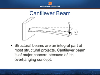
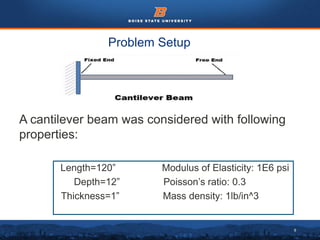
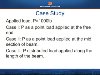
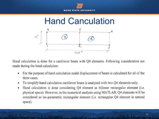
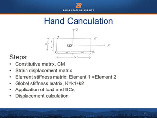
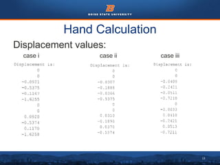
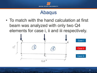
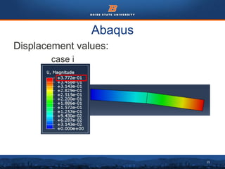
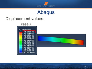
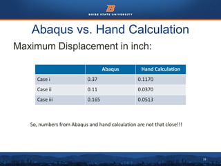
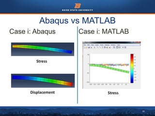
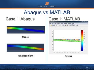
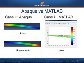
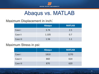
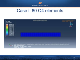
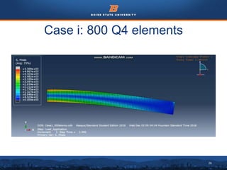
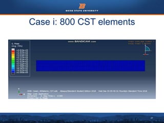
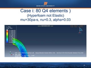
This document summarizes a finite element analysis of a cantilever beam using quadrilateral meshing elements. The beam is modeled and analyzed in Abaqus for three loading cases: a point load at the free end, a point load at the mid-section, and a distributed load along the length. Hand calculations are also performed and compared to Abaqus and MATLAB results. Increasing the number of elements improves accuracy of the models. Quadrilateral elements are preferred over triangular elements for beam bending problems. Maximum displacement occurs under a point load at the free end. The study concludes with recommendations for accurate beam modeling and design using finite element analysis.


