Seismic retrofitting of heritage building- case study

The Mani Mandir complex (100m×100m in plan) is an important historic monument of the town of Morbi in the western state of Gujarat, which suffered significant damage during the M7.7 Bhuj earthquake of 2001 in India. As part of the earthquake reconstruction program, the Government of Gujarat decided to seismically retrofit this complex. The project was divided into two phases of design and execution; this paper discusses the evaluation and design procedures recommended for exeuction. A detailed condition survey was carried out and measured drawings were prepared. A comprehensive retrofit program was formulated. Conservation principles, minimum intervention and consonance with the heritage character of the building were important considerations in selecting the retrofit program. The complex was modeled using finite elements and behaviour was studied of the existing structure as well as retrofit structure. The retrofit measures recommended included discriminate use of internal reinforced concrete skin walls, providing a rigid diaphragm behaviour mechanism in existing slabs, introducing stainless steel reinforcement bands in the existing masonry walls, cross-pinning and end-pinning in walls and pillars, and strengthening of arches and elevation features.

Recommended
More Related Content
What's hot
What's hot (20)
Similar to Seismic retrofitting of heritage building- case study
Similar to Seismic retrofitting of heritage building- case study (20)
More from ashlinvilson
Recently uploaded
Recently uploaded (20)
Seismic retrofitting of heritage building- case study
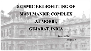
- 1. SEISMIC RETROFITTING OF MANI MANDIR COMPLEX AT MORBI, GUJARAT, INDIA Presented by Ashlin T V 1
- 2. 100m×100m in plan Historic monument 125 km from the epicenter of the 2001 Bhuj earthquake Morbi in the western state of Gujarat Western banks of the Macchu River Built in the 1930s by the ruler of Morbi Very ornate masonry building INTRODUCTION 2
- 3. Contd. Built in yellow sandstone in the tradition of the Indo-Saracenic style of architecture. The Secretariat building has a large central courtyard housing the Mani Mandir temple Total area of the Willingdon Secretariat is; - 4900m2 on ground floor - 4150m2 on first floor - 255m2 a part of second floor Fig. 1: Mani Mandir Complex 3
- 4. Principles that Governed The Seismic Retrofit Program Avoid intervention to maximum extent possible Introduce retrofitting measures in consonance with the heritage character and principles of conservation New elements must be non-intrusive and compatible with existing materials New elements must not be a cause of further damage (such as corrosion). Retrofit measures must be easy to implement 4
- 5. DAMAGE DOCUMENTATION Macro Survey Identifying the areas of severe, moderate and minor damage Areas that required emergency interventions Detailed Survey Floor-wise and Wing- wise To identify the types of damage Micro-Detailed Structural Survey Room-wise Documenting all damages including the extent of corrosion, the location of structural members and their sizes, and the length and width of cracks. 5
- 6. Two – storey complex Load bearing walls of soft, - yellow sandstone above plinth - black basalt stone below plinth Stone is dressed and exposed on external side - coated with paint or lime wash internally Ashlar-type masonry Fig. 2: Plan of Mani Mandir Complex EXISTING STRUCTURE 6
- 7. No physical bonds between stone blocks Stay in place by bearing friction Some stones locked by wooden keys – Chhatris ( ornamental canopies) - Shikhars ( decorative towers) The stone blocks of pillars are socketed into each other by a small tongue and groove detail Floors are built of stone slabs 750mm width and 200mm thick. Slabs wedged between flanges of steel joist Fig. 3: Stone Slab Wedged between Steel Joists 7
- 8. Joist rest on stone cornice Floor finish – 150mm thick Arches along external façade walls and internally across passages Fig. 4: Separation of Joist Flanges and Failure of Stone Slab 8
- 9. Damage Prior of 2001 Earthquake Corrosion of steel joists Damage to cornice pieces at the steel joist locations Weathering and flaking of sandstone Roof leakage Peeling of internal paint Damage in 1956 Earthquake Displacement of keystones of portals, arches Movement of stones of walls 9
- 10. Damage in 2001 Earthquake Severe damage and collapse of a large number of elements Extensive damage at the roof level Moderate damage at the first storey Little damage on the ground storey Staircase cap slabs, parapets, shikhars, arches, portals and chhatris above the roof were very badly damaged Bastions at the extreme corners of the structure sustained severe damage 10
- 11. Fig. 5: Damage above Roof Level: (a) Destruction of Arches in Elevational Elements, (b) Partial Collapse of Bastions 11
- 12. Fig. 6: Floor Level Damage: Fig. 7: Damage to Vertical Elements: (a) Openings of Joints in Arch; (b) Diagonal Cracks in Walls 12
- 13. Previous Attempts of Retrofit Keystones of some arches and stone blocks of a few walls and portals were stapled to adjacent stones Plastering the surface with cement mortar Arch pillars had been fully jacketed in concrete 13
- 14. Fig. 8: Earlier Interventions towards Restoration: (a) Fastening of Stones Using Mild Steel Staples; (b) Repairing of Weathered Stone. 14
- 15. BEHAVIOUR ANALYSIS Poor Bonding Between Stones Lack of Rigid Diaphragm Action of Slab Lack of Rigid Diaphragm Action of Slab Reentrant Corners Arches 15
- 16. STRUCTURALANALYSIS Material Tests Modeling and Analysis of the Existing Structure - Design Force Level for the Buildings - Modeling Verification of the Analysis and Structural Adequacy 16
- 17. METHODOLOGIES FOR REPAIR, RESTORATION AND RETROFITTING Elements to be Added/Enhanced for Improved Seismic Behaviour of Structure - Introducing rigid diaphragm action of slab - Enhancing Strength of the Structure - End-pinning of Wall Corners - Introducing Horizontal Reinforced Bands To Existing Masonry Walls - Strengthening of Arches - Cross-Pinning of Corridor Columns - Stitching and Grouting of Cracks in Walls 17
- 18. Fig. 7: Location of Proposed Bracings and R.C. Skin Walls at First Floor Level 18
- 19. Fig. 8: Sectional Details of Anchoring of Diagonal Floor Bracing in Walls 19
- 20. FIG. 9: Details of New R.C. Skin Wall (a) R.C. Skin Wall Nogged in to Masonry Wall; (b) New R.C. Skin Wall Foundation (a) (b) 20
- 21. Fig. 10: Intervention in Walls: (a) End Pining at Wall Corners; (b) Seismic Reinforcement Bands (a) (b) 21
- 22. Fig. 11: Detail of Interventions in Arches: (a) Strengthening of Arches Using Ties; (b) Strengthening Of Arches by Pining And Reinforcement Band. 22
- 23. Fig. 12: Interventions in Vertical Elements: (a) Cross Pining of Corridor Columns (b) Detail of Stitching Cracks in Walls 23
- 24. Areas Requiring Demolition and Rebuild - Roof Slab - Bastions - Elevation Features above Roof (Chhatris and Shikhars) and Decorative Balconies - Roof Parapets - Weather Sheds 24
- 25. Fig. 13: Plan of Bastion with New R.C. Skin Wall 25
- 26. Fig. 14 Pinning Details For Weather Shed 26
- 27. Conclusions The total area of new reinforced concrete skin walls introduced is less than 10% of the area of the existing masonry walls The estimated cost of the proposed retrofit worked out to less than Rs. 4300/m2 Reinforced concrete skin walls, diagonal bracing on the underside of the floor slabs for diaphragm action, horizontal stainless steel reinforcement bands in existing masonry walls have been proposed to improve lateral strength and behaviour Cross-pinning and end pinning have been recommended to improve the seismic behaviour of walls, weather sheds and stone pillars 27
- 28. REFERENCES Alpa Sheth et. al., (2004), “Seismic Retrofitting of Mani Mandir Complex at Morbi, Gujarat, India”, World Conference on Earthquake Engineering, 2430;1-6 28
- 29. Thank you 29