SlideShare a Scribd company logo
1 of 27
Download to read offline
Katrina Little
Sean S.
Electronics II
Lab #2: More Linear Operational Amplifier Applications
Goals:
To introduce the concepts of an operational amplifier (op-amp) used as a difference amplifier, an
instrumentation amplifier, and a voltage-to-current converter. Data collected during this
laboratory experiment will be compared to the theoretical equations for the appropriate circuits.
Additionally an application for the difference amplifier will be presented.
Equipment:
 Oscilloscope: DPO 4034B Mixed Signal
 Function Generator: AFG3022B
 Triple Power supply
 Breadboard
 TL081-TL084 family of operational amplifiers
 Capacitors available in the laboratory
 Resistors available in the laboratory
Pre-Laboratory:
a) Design a gain Ad = 2 difference amplifier using a minimum of 1k-ohm resistors
and the circuit diagram in Figure 3.
b) The difference amplifier needs two inputs V1 and V2.Simulate this difference
amplifier time transient response for an input for V1 equal to a 1.0 volt 200 Hz sine wave
and for V2 equal to a 1.0 volt 200 Hz sine wave but 180 degrees out of phase with the
V1.
c) Plot the input voltages as well as the output voltage as a function of time.
d) Repeat steps b and c but this time set the phase difference between V1 and V2 to 0
degrees.
e) Repeat steps a, b, c, and d for a gain Ad = 4 difference amplifier.
f) Design a gain Ad = 2 instrumentation amplifier using a minimum of 1k-ohm resistors and
the circuit diagram in Figure 5.
g) The instrumentation amplifier needs two inputs V1 and V2. Simulate this
instrumentation amplifier time transient response for an input for V1 equal to a 1.0 volt
200 Hz sine wave and for V2 equal to a 1.0 volt 200 Hz sine wave but 180 degrees out of
phase with the V1.
h) Plot the input voltages as well as the output voltage as a function of time.
i) Repeat steps g and h but this time set the phase difference between V1 and V2 to 0
degrees.
j) Repeat steps f, g, h, and i for a gain Ad = 4 instrumentation amplifier.
k) Design a voltage-to-current converter that produces an output of 1ma for every volt of
input using a minimum of 1k-ohm resistors and the circuit diagram in Figure 6.
l) Simulate the voltage to converter designed in step k for V2 = 3 volts and Vin = 2 volts.
m) Vary V3 between 1 volt and 5 volts and plot Iout versus V3.
Procedure:
General Setup:
1. Record the model and serial number of the scope, power supply, multimeter and function
generator used in laboratory experiment.
2. Download the datasheet for the op-amp used. This will be needed to obtain the pin-out of
the op-amp used. When comparing datasheet data values to experimental data use the
typical values in the datasheet if given.
3. Make sure that the power supply to the op-amp is correctly wired as not to apply the
incorrect polarity to the op-amp.
4. Initially set +Vcc = 15 volts and -Vcc to -15 volts
5. When measuring any values make sure to measure all inputs as well as the output of the
circuit. Do not rely on the values indicated on the instruments. Always measure all signal
values.
6. The output impedance of the signal generator is 50 ohms. If the generator is connected to a load
other than 50 ohms, the displayed Amplitude, Offset, and High/Low values will be different than
what is selected on the generator. Usually a factor of 2 larger.
7. Before turning any power on double check the wiring to make sure that it is correct.
8. Measure all resistors that are used in the amplifier circuits using the multimeter and
record these values.
9. Use all measured values to determine experimental results such as gain and current.
10. Comparing data means to calculate the percent difference between two values. For
example, theoretical values versus measured values.
11. Comparing data graphically means to plot the data on the same plot to see how the data
overlaps.
12. Obtain the pin out for the 2N2222 transistor
Difference Amplifier:
1. Using the parts kit in the lab, design the difference amplifier of Figure 3 with a gain of
Ad = 2 using 1k ohm resistors for R1 and R3.
R4 = R2 = 2kΩ
2. Measure with the multimeter the actual resistance values.
R1 = 0.987 kΩ
R2 = 1.956 kΩ
R3 = 0.991 kΩ
R4 = 1.959 kΩ
3. Compute Acm and Ad using Equations (12) and (14).
Acm = -.0047
* ½
Ad = 1.9794
4. Also calculate the CMMR using Equation (15).
CMRR = 52.423
5. Build the gain of Ad = 2 difference amplifier.
6. Setting V1 = V2 = 20 volt peak-to-peak 200 Hz sine wave measure Vout.
7. Calculate from step 6 Acm = Vout / V1.
Acm = 24/19.2 = 1.25
8. Varying the frequency of the function generator from 100 Hz to 100 kHz repeat steps 6,
and 7. Use measured values at frequencies of 1X, 2X and 5X for each decade.
Input of 20Vpp
f (Hz) Vout (V) Acm=(Vout/V1)
100 1.079 mV 0.00005297
200 1.081 mV 0.00005406
500 1.083 mV 0.00005416
1 K 1.099 mV 0.00005497
2K 1.135 mV 0.0000568
5K 1.238 mV 0.00006198
10K 1.735 mV 0.00008708
20K 2.283mV 0.0001146
50K 5.431mV 0.002742
100K 6.546 mV 0.0003274
9. Setting V1 = 1 volt peak-to-peak 200 Hz sine wave and V2 = -V1. To generate V2 = -V1,
build an inverting amplifier1 with a gain equal to –1. Apply the function generator to V1
input to the difference amplifier and to the inverting amplifier. The output of the inverter
is now equal to -V1 and can be applied to V2 input to the difference amplifier.
10. Measure Vout from step 9.
Vout = 3.72 V
11. Calculate Ad from step 9 (Ad = Vout / (2*V1).
Ad =2.214
12. Using Equation (15) calculate the CMRR from Acm from Step 7 and Ad from Step 10.
CMRR = 4.9654
13. Compare step 12 to step 4.
14. Discuss in the laboratory report the result of step 13.
15. Varying the frequency of the function generator from 100 Hz to 100 kHz repeat steps 9,
10, and 11. Use measured values at frequencies of 1X, 2X and 5X for each decade.
Input of 1Vpp
f(Hz) Vout (V) Ad = Vout /(2xV1)
100 3.992 1.99972
200 3.998 2.010055
500 3.999 1.99993
1 K 3.999 2.00041
2K 3.999 1.99994
5K 3.98 2.001215
10K 3.987 2.001874
20K 3.998 2.00868
50K 3.99 1.99499
100K 3.967 1.98614
16. From steps 14, 15 calculate CMRR as a function of frequency.
f (Hz) Acm=(Vout/V1) Ad = Vout /(2xV1) CMRR
100 0.00005297 1.99972 91.5278
200 0.00005406 2.010055 91.4066
500 0.00005416 1.99993 91.3467
1 K 0.00005497 2.00041 91.2199
2K 0.0000568 1.99994 91.2178
5K 0.00006198 2.001215 90.1808
10K 0.00008708 2.001874 87.2304
20K 0.0001146 2.00868 84.8745
50K 0.002742 1.99499 77.2375
100K 0.0003274 1.98614 55.6586
17. From steps 14, 15 and 16 plot Acm, Ad, CMRR as a function of Frequency.
18. Decrease the value of R4 by 15 % to 20 %. Add a 10K ohm variable resistor in series
with this new value of R4. One side of the variable resistor to R4 and the middle
connection to ground. See Figure 7.
19. Setting V1 = V2 = 20 volt peak-to-peak 200 Hz sine wave measure Vout. Adjust this
variable resistor (potentiometer) to yield the smallest value for Vout. Adjust R4 to best
match R2 (This is the optimum setting).
Vout = 1.9V
20. Repeat steps 6,7, 9, 10, and 11 with this optimum setting for the potentiometer.
Acm = 1.9
0
10
20
30
40
50
60
70
80
90
100
Acm=(Vout/V1)
Ad = Vout /(2xV1)
CMRR
Vout = 3.76V
Vin = 960 mV
21. Build a gain of Ad = 4 difference amplifier.
22. Repeat steps 6, 7, 9, 10, and 11 for the difference amplifier of step 21.
23. Build the test circuit shown in Figure 8 with a gain of Ad = 4 for the difference amplifier.
This allows for two voltage sources to be applied to V1 and V2 of the difference
amplifier. The op-amp circuit of U2 inverts V1 adding 180 degree phase shift. U1 and U3
are unity gain summers, summing V2 and V1 to produce two signals into the difference
amplifier:
Vout(U1) = - V1 - V2 (36)
Vout(U3) = +V1 - V2 (37)
24. Set V1 to a 0.5 volt peak-to-peak 200 Hz sine wave. Also set V2 to a 0.5 volt peak-to-
peak 20 Hz sine wave.
25. Measure and record with oscilloscope the outputs U1 and U2 op-amp stages.
U1 Vout = 900mV
U2 Vout = 500mV
26. Measure and record Vout with the Oscilloscope.
Vout = 3.54V
27. Discuss in the laboratory report the results of steps 25 and 26.
Instrumentation Amplifier:
1. Using the parts kit in the lab, build the instrumentation amplifier of Figure 5 with a gain
of Ad = 2 using 1k ohm resistors for R21, R3, and R7.
2. Measure with the multimeter the actual resistance values.
R1 = .978 kΩ
R2 = .978 kΩ
R3 = .975 kΩ
R4 = .987 kΩ
R5 = .468 kΩ
R6 = .467 kΩ
R7 = .990 kΩ
3. Compute Acm and Ad using Equations (22) and (23).
Ad = 2
Acm = 0
4. Also calculate the CMMR using Equation (15).
CMMR =
5. Setting V1 = V2 = 20 volt peak-to-peak 200 Hz sine wave measure Vout.
Vout = 128mV
6. Calculate from step 5 Acm = Vout / V1.
Acm = 0.0003136
7. Setting V1 = 1 volt peak-to-peak 200 Hz sine wave and V2 = -V1. To generate V2 = -V1,
build an inverting amplifier2 with a gain equal to -1. Apply the function generator to V1
input to the difference amplifier and to the inverting amplifier. The output of the inverter
is now equal to -V1 and can be applied to V2 input to the difference amplifier.
8. Measure Vout from step 7.
Vout = 3.96V
9. Calculate Ad from step 8 (Ad = Vout / (2*V1).
Ad = 1.9975
10. Using Equation (24) calculate the CMRR from Acm from Step 6 and Ad from Step 9.
CMMR = 96.082 dB
11. Compare step 10 to step 4.
12. Discuss in the laboratory report the result of step 11.
13. Varying the frequency of the function generator from 100 Hz to 100 kHz repeat steps 5,
and 6. Use measured values at frequencies of 1X, 2X and 5X for each decade.
14. Varying the frequency of the function generator from 100 Hz to 100 kHz repeat steps 7,
8, and 9. Use measured values at frequencies of 1X, 2X and 5X for each decade.
15. From steps 13 and 14 calculate CMRR as a function of frequency.
16. From steps 13, 14, and 15 plot Acm, Ad, CMRR as a function of Frequency.
Voltage to Current Converter:
1. Design and build the voltage to current converter given in Figure 6 for a conversion
factor of 1milliamp of out for one volt of input.
2. Using a load resistance of RL = 1k ohms and V2 = 15 volts measure the voltage across
R2 and RL for Vin = 1 volt
VRL = 1.012V
VR2 = .9997V
3. Compute the current in RL and R2 from step 2.
IL = I2 = Vin/R2 = 1mA
4. Varying the input from 0 to 5 volts, repeat steps 2 and 3. Make sure there is at least 5
points measured per integer voltage value.
5. Plot IL versus Vin from step 4. Is the curve linear?
6. Setting Vin to 2 volts measure IL as a function of V2 with V2 varying from 1 volt to 5
volts.
7. Plot IL versus V2.
8. Setting Vin to 2 volts and V2 to 5 volts measure Vin with RL varying from 100 ohms to
2k ohms. Use at least 5 different resistor values for RL.
9. Plot IL versus RL.

More Related Content

What's hot

Impulse testing of transformer
Impulse testing of transformerImpulse testing of transformer
Impulse testing of transformerPreet_patel
 
Rc phase shift oscillator
Rc phase shift oscillatorRc phase shift oscillator
Rc phase shift oscillatorRaj Mehra Mehar
 
Electronic Measurement - Power Factor Meter
Electronic Measurement - Power Factor MeterElectronic Measurement - Power Factor Meter
Electronic Measurement - Power Factor MeterBurdwan University
 
Lab 8 bipolar junction transistor characterstics
Lab 8  bipolar junction transistor charactersticsLab 8  bipolar junction transistor characterstics
Lab 8 bipolar junction transistor charactersticskehali Haileselassie
 
Power Transformer Differential protection
Power Transformer Differential protectionPower Transformer Differential protection
Power Transformer Differential protectionRishi Tandon
 
Power System Modeling Presentation
Power System Modeling PresentationPower System Modeling Presentation
Power System Modeling PresentationChaitra Panat
 
High voltage testing of electrical transformer
High voltage testing of electrical transformerHigh voltage testing of electrical transformer
High voltage testing of electrical transformerPraveenKumar5880
 
Power system fault analysis ppt
Power system fault analysis pptPower system fault analysis ppt
Power system fault analysis pptkarikalan123
 
Two port networks unit ii
Two port networks unit iiTwo port networks unit ii
Two port networks unit iimrecedu
 
Advantages of three phase system over single phase system
Advantages of three phase system over single phase systemAdvantages of three phase system over single phase system
Advantages of three phase system over single phase systemDr.Raja R
 
Generator protection calculations settings
Generator protection calculations settingsGenerator protection calculations settings
Generator protection calculations settingsmichaeljmack
 

What's hot (20)

Impulse testing of transformer
Impulse testing of transformerImpulse testing of transformer
Impulse testing of transformer
 
Rc phase shift oscillator
Rc phase shift oscillatorRc phase shift oscillator
Rc phase shift oscillator
 
Content beyond syllabus
Content beyond syllabusContent beyond syllabus
Content beyond syllabus
 
Electronic Measurement - Power Factor Meter
Electronic Measurement - Power Factor MeterElectronic Measurement - Power Factor Meter
Electronic Measurement - Power Factor Meter
 
Lab 8 bipolar junction transistor characterstics
Lab 8  bipolar junction transistor charactersticsLab 8  bipolar junction transistor characterstics
Lab 8 bipolar junction transistor characterstics
 
Power Transformer Differential protection
Power Transformer Differential protectionPower Transformer Differential protection
Power Transformer Differential protection
 
Power System Modeling Presentation
Power System Modeling PresentationPower System Modeling Presentation
Power System Modeling Presentation
 
Lecture 10
Lecture 10Lecture 10
Lecture 10
 
Per unit analysis
Per unit analysisPer unit analysis
Per unit analysis
 
High voltage testing of electrical transformer
High voltage testing of electrical transformerHigh voltage testing of electrical transformer
High voltage testing of electrical transformer
 
Power system fault analysis ppt
Power system fault analysis pptPower system fault analysis ppt
Power system fault analysis ppt
 
Lecture 5
Lecture 5Lecture 5
Lecture 5
 
Ec ii lab manual
Ec ii lab manualEc ii lab manual
Ec ii lab manual
 
Two port networks unit ii
Two port networks unit iiTwo port networks unit ii
Two port networks unit ii
 
Fault analysis using z bus
Fault analysis using z busFault analysis using z bus
Fault analysis using z bus
 
Boost converter
Boost converterBoost converter
Boost converter
 
Advantages of three phase system over single phase system
Advantages of three phase system over single phase systemAdvantages of three phase system over single phase system
Advantages of three phase system over single phase system
 
Inverter
InverterInverter
Inverter
 
Generator protection calculations settings
Generator protection calculations settingsGenerator protection calculations settings
Generator protection calculations settings
 
Experiment 1 DC Machine
Experiment 1 DC MachineExperiment 1 DC Machine
Experiment 1 DC Machine
 

Similar to Lab 2 Report More Linear Operational Amplifiers

Instrumentation Lab. Experiment #4 Report: Op-Amps: Integrator, Differentiato...
Instrumentation Lab. Experiment #4 Report: Op-Amps: Integrator, Differentiato...Instrumentation Lab. Experiment #4 Report: Op-Amps: Integrator, Differentiato...
Instrumentation Lab. Experiment #4 Report: Op-Amps: Integrator, Differentiato...mohammad zeyad
 
EEE 117L Network Analysis Laboratory Lab 1 1
EEE 117L Network Analysis Laboratory  Lab 1     1  EEE 117L Network Analysis Laboratory  Lab 1     1
EEE 117L Network Analysis Laboratory Lab 1 1 EvonCanales257
 
Power Electronics Lab Manual Spring 2017
Power Electronics Lab Manual Spring 2017Power Electronics Lab Manual Spring 2017
Power Electronics Lab Manual Spring 2017Zeeshan Ahmed
 
9. article azojete vol 11 103 113 dibal
9. article azojete vol 11 103 113 dibal9. article azojete vol 11 103 113 dibal
9. article azojete vol 11 103 113 dibalOyeniyi Samuel
 
Instrumentation Lab. Experiment #3 Report: Operational Amplifiers
Instrumentation Lab. Experiment #3 Report: Operational AmplifiersInstrumentation Lab. Experiment #3 Report: Operational Amplifiers
Instrumentation Lab. Experiment #3 Report: Operational Amplifiersmohammad zeyad
 
Function Generator
Function GeneratorFunction Generator
Function Generatorraj singh
 
SIGNAL SPECTRA EXPERIMENT 1 - FINALS (for AGDON)
SIGNAL SPECTRA EXPERIMENT 1 - FINALS (for AGDON)SIGNAL SPECTRA EXPERIMENT 1 - FINALS (for AGDON)
SIGNAL SPECTRA EXPERIMENT 1 - FINALS (for AGDON)Sarah Krystelle
 
Experiment reportexample
Experiment reportexampleExperiment reportexample
Experiment reportexampleAnurag Farkya
 
Ic apps lab_manual_jwfiles
Ic apps lab_manual_jwfilesIc apps lab_manual_jwfiles
Ic apps lab_manual_jwfilesVijay Kumar
 
Introduction to Oscilloscope and Function generator
Introduction to Oscilloscope and Function generatorIntroduction to Oscilloscope and Function generator
Introduction to Oscilloscope and Function generatorcyberns_
 
Lab 7 diode with operational amplifiers by kehali b. haileselassie and kou
Lab 7  diode with operational amplifiers by kehali b. haileselassie and kouLab 7  diode with operational amplifiers by kehali b. haileselassie and kou
Lab 7 diode with operational amplifiers by kehali b. haileselassie and koukehali Haileselassie
 
SIGNAL SPECTRA EXPERIMENT 1 - FINALS (for ABDON)
SIGNAL SPECTRA EXPERIMENT 1 - FINALS (for ABDON)SIGNAL SPECTRA EXPERIMENT 1 - FINALS (for ABDON)
SIGNAL SPECTRA EXPERIMENT 1 - FINALS (for ABDON)Sarah Krystelle
 

Similar to Lab 2 Report More Linear Operational Amplifiers (20)

EEL782_Project
EEL782_ProjectEEL782_Project
EEL782_Project
 
Instrumentation Lab. Experiment #4 Report: Op-Amps: Integrator, Differentiato...
Instrumentation Lab. Experiment #4 Report: Op-Amps: Integrator, Differentiato...Instrumentation Lab. Experiment #4 Report: Op-Amps: Integrator, Differentiato...
Instrumentation Lab. Experiment #4 Report: Op-Amps: Integrator, Differentiato...
 
EEE 117L Network Analysis Laboratory Lab 1 1
EEE 117L Network Analysis Laboratory  Lab 1     1  EEE 117L Network Analysis Laboratory  Lab 1     1
EEE 117L Network Analysis Laboratory Lab 1 1
 
EE101 Lab4 Guillemaud
EE101 Lab4 GuillemaudEE101 Lab4 Guillemaud
EE101 Lab4 Guillemaud
 
Power Electronics Lab Manual Spring 2017
Power Electronics Lab Manual Spring 2017Power Electronics Lab Manual Spring 2017
Power Electronics Lab Manual Spring 2017
 
Lab1
Lab1Lab1
Lab1
 
9. article azojete vol 11 103 113 dibal
9. article azojete vol 11 103 113 dibal9. article azojete vol 11 103 113 dibal
9. article azojete vol 11 103 113 dibal
 
Instrumentation Lab. Experiment #3 Report: Operational Amplifiers
Instrumentation Lab. Experiment #3 Report: Operational AmplifiersInstrumentation Lab. Experiment #3 Report: Operational Amplifiers
Instrumentation Lab. Experiment #3 Report: Operational Amplifiers
 
Function Generator
Function GeneratorFunction Generator
Function Generator
 
project.pptx
project.pptxproject.pptx
project.pptx
 
SIGNAL SPECTRA EXPERIMENT 1 - FINALS (for AGDON)
SIGNAL SPECTRA EXPERIMENT 1 - FINALS (for AGDON)SIGNAL SPECTRA EXPERIMENT 1 - FINALS (for AGDON)
SIGNAL SPECTRA EXPERIMENT 1 - FINALS (for AGDON)
 
Experiment reportexample
Experiment reportexampleExperiment reportexample
Experiment reportexample
 
Ic apps lab_manual_jwfiles
Ic apps lab_manual_jwfilesIc apps lab_manual_jwfiles
Ic apps lab_manual_jwfiles
 
Introduction to Oscilloscope and Function generator
Introduction to Oscilloscope and Function generatorIntroduction to Oscilloscope and Function generator
Introduction to Oscilloscope and Function generator
 
ECE_468_Report_Sid_AB
ECE_468_Report_Sid_ABECE_468_Report_Sid_AB
ECE_468_Report_Sid_AB
 
48096558 ec2258-lm
48096558 ec2258-lm48096558 ec2258-lm
48096558 ec2258-lm
 
Lab 7 diode with operational amplifiers by kehali b. haileselassie and kou
Lab 7  diode with operational amplifiers by kehali b. haileselassie and kouLab 7  diode with operational amplifiers by kehali b. haileselassie and kou
Lab 7 diode with operational amplifiers by kehali b. haileselassie and kou
 
SIGNAL SPECTRA EXPERIMENT 1 - FINALS (for ABDON)
SIGNAL SPECTRA EXPERIMENT 1 - FINALS (for ABDON)SIGNAL SPECTRA EXPERIMENT 1 - FINALS (for ABDON)
SIGNAL SPECTRA EXPERIMENT 1 - FINALS (for ABDON)
 
Exp f1 maycen
Exp f1 maycenExp f1 maycen
Exp f1 maycen
 
Dt4301719726
Dt4301719726Dt4301719726
Dt4301719726
 

More from Katrina Little

Electronics ii hand written formula sheets
Electronics ii hand written formula sheetsElectronics ii hand written formula sheets
Electronics ii hand written formula sheetsKatrina Little
 
Embedded Systems Design of Hexidecimal Calculator
Embedded Systems Design of Hexidecimal Calculator Embedded Systems Design of Hexidecimal Calculator
Embedded Systems Design of Hexidecimal Calculator Katrina Little
 
MATLAB / Simulink: Inverted Pendulum on a Moving Cart
MATLAB / Simulink: Inverted Pendulum on a Moving Cart MATLAB / Simulink: Inverted Pendulum on a Moving Cart
MATLAB / Simulink: Inverted Pendulum on a Moving Cart Katrina Little
 
MATLAB / Simulink HW for Linear Control Systems
MATLAB / Simulink HW for Linear Control Systems MATLAB / Simulink HW for Linear Control Systems
MATLAB / Simulink HW for Linear Control Systems Katrina Little
 
Experiment 2, Diode Applications
Experiment 2, Diode ApplicationsExperiment 2, Diode Applications
Experiment 2, Diode ApplicationsKatrina Little
 
Experiment 6, 3-Stage BJT Amplifier Design Project
Experiment 6, 3-Stage BJT Amplifier Design ProjectExperiment 6, 3-Stage BJT Amplifier Design Project
Experiment 6, 3-Stage BJT Amplifier Design ProjectKatrina Little
 
Experiment 5, Transistor Small Signal Amplifiers
Experiment 5, Transistor Small Signal AmplifiersExperiment 5, Transistor Small Signal Amplifiers
Experiment 5, Transistor Small Signal AmplifiersKatrina Little
 
Experiment 4, Transistor AC Amplifiers
Experiment 4, Transistor AC AmplifiersExperiment 4, Transistor AC Amplifiers
Experiment 4, Transistor AC AmplifiersKatrina Little
 
Experiment 3 Low Pass Filter
Experiment 3 Low Pass Filter Experiment 3 Low Pass Filter
Experiment 3 Low Pass Filter Katrina Little
 
Lab 4 EEL 3552 Amplitude Modulation with MATLAB Simulations
Lab 4 EEL 3552 Amplitude Modulation with MATLAB SimulationsLab 4 EEL 3552 Amplitude Modulation with MATLAB Simulations
Lab 4 EEL 3552 Amplitude Modulation with MATLAB SimulationsKatrina Little
 
RC Circuit Transfer Functions with Bode Diagrams
RC Circuit Transfer Functions with Bode Diagrams RC Circuit Transfer Functions with Bode Diagrams
RC Circuit Transfer Functions with Bode Diagrams Katrina Little
 
Lab 9 D-Flip Flops: Shift Register and Sequence Counter
Lab 9 D-Flip Flops: Shift Register and Sequence CounterLab 9 D-Flip Flops: Shift Register and Sequence Counter
Lab 9 D-Flip Flops: Shift Register and Sequence CounterKatrina Little
 
Lab 7 -RAM and ROM, Xilinx, Digelent BASYS experimentor board
Lab 7 -RAM and ROM, Xilinx, Digelent BASYS experimentor boardLab 7 -RAM and ROM, Xilinx, Digelent BASYS experimentor board
Lab 7 -RAM and ROM, Xilinx, Digelent BASYS experimentor boardKatrina Little
 
Lab 4 Three-Bit Binary Adder
Lab 4 Three-Bit Binary AdderLab 4 Three-Bit Binary Adder
Lab 4 Three-Bit Binary AdderKatrina Little
 
Lab 3 Multi-Function Gate
Lab 3   Multi-Function GateLab 3   Multi-Function Gate
Lab 3 Multi-Function GateKatrina Little
 
Lab 2-Simple Combinational Logic
Lab 2-Simple Combinational LogicLab 2-Simple Combinational Logic
Lab 2-Simple Combinational LogicKatrina Little
 
Senior design power supply pcb eagle_cad
Senior design power supply pcb eagle_cadSenior design power supply pcb eagle_cad
Senior design power supply pcb eagle_cadKatrina Little
 
MATLAB: Output Voltage of Series RC Circuit utilizing Euler Approximations
MATLAB: Output Voltage of Series RC Circuit utilizing Euler Approximations MATLAB: Output Voltage of Series RC Circuit utilizing Euler Approximations
MATLAB: Output Voltage of Series RC Circuit utilizing Euler Approximations Katrina Little
 
Semiconductors exam(s) hand written formula sheets
Semiconductors exam(s) hand written formula sheetsSemiconductors exam(s) hand written formula sheets
Semiconductors exam(s) hand written formula sheetsKatrina Little
 
Photonics exams hand written formulas
Photonics exams hand written formulasPhotonics exams hand written formulas
Photonics exams hand written formulasKatrina Little
 

More from Katrina Little (20)

Electronics ii hand written formula sheets
Electronics ii hand written formula sheetsElectronics ii hand written formula sheets
Electronics ii hand written formula sheets
 
Embedded Systems Design of Hexidecimal Calculator
Embedded Systems Design of Hexidecimal Calculator Embedded Systems Design of Hexidecimal Calculator
Embedded Systems Design of Hexidecimal Calculator
 
MATLAB / Simulink: Inverted Pendulum on a Moving Cart
MATLAB / Simulink: Inverted Pendulum on a Moving Cart MATLAB / Simulink: Inverted Pendulum on a Moving Cart
MATLAB / Simulink: Inverted Pendulum on a Moving Cart
 
MATLAB / Simulink HW for Linear Control Systems
MATLAB / Simulink HW for Linear Control Systems MATLAB / Simulink HW for Linear Control Systems
MATLAB / Simulink HW for Linear Control Systems
 
Experiment 2, Diode Applications
Experiment 2, Diode ApplicationsExperiment 2, Diode Applications
Experiment 2, Diode Applications
 
Experiment 6, 3-Stage BJT Amplifier Design Project
Experiment 6, 3-Stage BJT Amplifier Design ProjectExperiment 6, 3-Stage BJT Amplifier Design Project
Experiment 6, 3-Stage BJT Amplifier Design Project
 
Experiment 5, Transistor Small Signal Amplifiers
Experiment 5, Transistor Small Signal AmplifiersExperiment 5, Transistor Small Signal Amplifiers
Experiment 5, Transistor Small Signal Amplifiers
 
Experiment 4, Transistor AC Amplifiers
Experiment 4, Transistor AC AmplifiersExperiment 4, Transistor AC Amplifiers
Experiment 4, Transistor AC Amplifiers
 
Experiment 3 Low Pass Filter
Experiment 3 Low Pass Filter Experiment 3 Low Pass Filter
Experiment 3 Low Pass Filter
 
Lab 4 EEL 3552 Amplitude Modulation with MATLAB Simulations
Lab 4 EEL 3552 Amplitude Modulation with MATLAB SimulationsLab 4 EEL 3552 Amplitude Modulation with MATLAB Simulations
Lab 4 EEL 3552 Amplitude Modulation with MATLAB Simulations
 
RC Circuit Transfer Functions with Bode Diagrams
RC Circuit Transfer Functions with Bode Diagrams RC Circuit Transfer Functions with Bode Diagrams
RC Circuit Transfer Functions with Bode Diagrams
 
Lab 9 D-Flip Flops: Shift Register and Sequence Counter
Lab 9 D-Flip Flops: Shift Register and Sequence CounterLab 9 D-Flip Flops: Shift Register and Sequence Counter
Lab 9 D-Flip Flops: Shift Register and Sequence Counter
 
Lab 7 -RAM and ROM, Xilinx, Digelent BASYS experimentor board
Lab 7 -RAM and ROM, Xilinx, Digelent BASYS experimentor boardLab 7 -RAM and ROM, Xilinx, Digelent BASYS experimentor board
Lab 7 -RAM and ROM, Xilinx, Digelent BASYS experimentor board
 
Lab 4 Three-Bit Binary Adder
Lab 4 Three-Bit Binary AdderLab 4 Three-Bit Binary Adder
Lab 4 Three-Bit Binary Adder
 
Lab 3 Multi-Function Gate
Lab 3   Multi-Function GateLab 3   Multi-Function Gate
Lab 3 Multi-Function Gate
 
Lab 2-Simple Combinational Logic
Lab 2-Simple Combinational LogicLab 2-Simple Combinational Logic
Lab 2-Simple Combinational Logic
 
Senior design power supply pcb eagle_cad
Senior design power supply pcb eagle_cadSenior design power supply pcb eagle_cad
Senior design power supply pcb eagle_cad
 
MATLAB: Output Voltage of Series RC Circuit utilizing Euler Approximations
MATLAB: Output Voltage of Series RC Circuit utilizing Euler Approximations MATLAB: Output Voltage of Series RC Circuit utilizing Euler Approximations
MATLAB: Output Voltage of Series RC Circuit utilizing Euler Approximations
 
Semiconductors exam(s) hand written formula sheets
Semiconductors exam(s) hand written formula sheetsSemiconductors exam(s) hand written formula sheets
Semiconductors exam(s) hand written formula sheets
 
Photonics exams hand written formulas
Photonics exams hand written formulasPhotonics exams hand written formulas
Photonics exams hand written formulas
 

Recently uploaded

High Profile Call Girls Nagpur Isha Call 7001035870 Meet With Nagpur Escorts
High Profile Call Girls Nagpur Isha Call 7001035870 Meet With Nagpur EscortsHigh Profile Call Girls Nagpur Isha Call 7001035870 Meet With Nagpur Escorts
High Profile Call Girls Nagpur Isha Call 7001035870 Meet With Nagpur Escortsranjana rawat
 
VIP Call Girls Service Kondapur Hyderabad Call +91-8250192130
VIP Call Girls Service Kondapur Hyderabad Call +91-8250192130VIP Call Girls Service Kondapur Hyderabad Call +91-8250192130
VIP Call Girls Service Kondapur Hyderabad Call +91-8250192130Suhani Kapoor
 
VIP Call Girls Service Hitech City Hyderabad Call +91-8250192130
VIP Call Girls Service Hitech City Hyderabad Call +91-8250192130VIP Call Girls Service Hitech City Hyderabad Call +91-8250192130
VIP Call Girls Service Hitech City Hyderabad Call +91-8250192130Suhani Kapoor
 
Microscopic Analysis of Ceramic Materials.pptx
Microscopic Analysis of Ceramic Materials.pptxMicroscopic Analysis of Ceramic Materials.pptx
Microscopic Analysis of Ceramic Materials.pptxpurnimasatapathy1234
 
Booking open Available Pune Call Girls Koregaon Park 6297143586 Call Hot Ind...
Booking open Available Pune Call Girls Koregaon Park  6297143586 Call Hot Ind...Booking open Available Pune Call Girls Koregaon Park  6297143586 Call Hot Ind...
Booking open Available Pune Call Girls Koregaon Park 6297143586 Call Hot Ind...Call Girls in Nagpur High Profile
 
Introduction to Multiple Access Protocol.pptx
Introduction to Multiple Access Protocol.pptxIntroduction to Multiple Access Protocol.pptx
Introduction to Multiple Access Protocol.pptxupamatechverse
 
IMPLICATIONS OF THE ABOVE HOLISTIC UNDERSTANDING OF HARMONY ON PROFESSIONAL E...
IMPLICATIONS OF THE ABOVE HOLISTIC UNDERSTANDING OF HARMONY ON PROFESSIONAL E...IMPLICATIONS OF THE ABOVE HOLISTIC UNDERSTANDING OF HARMONY ON PROFESSIONAL E...
IMPLICATIONS OF THE ABOVE HOLISTIC UNDERSTANDING OF HARMONY ON PROFESSIONAL E...RajaP95
 
MANUFACTURING PROCESS-II UNIT-2 LATHE MACHINE
MANUFACTURING PROCESS-II UNIT-2 LATHE MACHINEMANUFACTURING PROCESS-II UNIT-2 LATHE MACHINE
MANUFACTURING PROCESS-II UNIT-2 LATHE MACHINESIVASHANKAR N
 
the ladakh protest in leh ladakh 2024 sonam wangchuk.pptx
the ladakh protest in leh ladakh 2024 sonam wangchuk.pptxthe ladakh protest in leh ladakh 2024 sonam wangchuk.pptx
the ladakh protest in leh ladakh 2024 sonam wangchuk.pptxhumanexperienceaaa
 
Call for Papers - African Journal of Biological Sciences, E-ISSN: 2663-2187, ...
Call for Papers - African Journal of Biological Sciences, E-ISSN: 2663-2187, ...Call for Papers - African Journal of Biological Sciences, E-ISSN: 2663-2187, ...
Call for Papers - African Journal of Biological Sciences, E-ISSN: 2663-2187, ...Christo Ananth
 
Call Girls in Nagpur Suman Call 7001035870 Meet With Nagpur Escorts
Call Girls in Nagpur Suman Call 7001035870 Meet With Nagpur EscortsCall Girls in Nagpur Suman Call 7001035870 Meet With Nagpur Escorts
Call Girls in Nagpur Suman Call 7001035870 Meet With Nagpur EscortsCall Girls in Nagpur High Profile
 
(ANJALI) Dange Chowk Call Girls Just Call 7001035870 [ Cash on Delivery ] Pun...
(ANJALI) Dange Chowk Call Girls Just Call 7001035870 [ Cash on Delivery ] Pun...(ANJALI) Dange Chowk Call Girls Just Call 7001035870 [ Cash on Delivery ] Pun...
(ANJALI) Dange Chowk Call Girls Just Call 7001035870 [ Cash on Delivery ] Pun...ranjana rawat
 
(TARA) Talegaon Dabhade Call Girls Just Call 7001035870 [ Cash on Delivery ] ...
(TARA) Talegaon Dabhade Call Girls Just Call 7001035870 [ Cash on Delivery ] ...(TARA) Talegaon Dabhade Call Girls Just Call 7001035870 [ Cash on Delivery ] ...
(TARA) Talegaon Dabhade Call Girls Just Call 7001035870 [ Cash on Delivery ] ...ranjana rawat
 
High Profile Call Girls Nagpur Meera Call 7001035870 Meet With Nagpur Escorts
High Profile Call Girls Nagpur Meera Call 7001035870 Meet With Nagpur EscortsHigh Profile Call Girls Nagpur Meera Call 7001035870 Meet With Nagpur Escorts
High Profile Call Girls Nagpur Meera Call 7001035870 Meet With Nagpur EscortsCall Girls in Nagpur High Profile
 
Introduction to IEEE STANDARDS and its different types.pptx
Introduction to IEEE STANDARDS and its different types.pptxIntroduction to IEEE STANDARDS and its different types.pptx
Introduction to IEEE STANDARDS and its different types.pptxupamatechverse
 
Introduction and different types of Ethernet.pptx
Introduction and different types of Ethernet.pptxIntroduction and different types of Ethernet.pptx
Introduction and different types of Ethernet.pptxupamatechverse
 
The Most Attractive Pune Call Girls Budhwar Peth 8250192130 Will You Miss Thi...
The Most Attractive Pune Call Girls Budhwar Peth 8250192130 Will You Miss Thi...The Most Attractive Pune Call Girls Budhwar Peth 8250192130 Will You Miss Thi...
The Most Attractive Pune Call Girls Budhwar Peth 8250192130 Will You Miss Thi...ranjana rawat
 
Call Girls Service Nashik Vaishnavi 7001305949 Independent Escort Service Nashik
Call Girls Service Nashik Vaishnavi 7001305949 Independent Escort Service NashikCall Girls Service Nashik Vaishnavi 7001305949 Independent Escort Service Nashik
Call Girls Service Nashik Vaishnavi 7001305949 Independent Escort Service NashikCall Girls in Nagpur High Profile
 
SPICE PARK APR2024 ( 6,793 SPICE Models )
SPICE PARK APR2024 ( 6,793 SPICE Models )SPICE PARK APR2024 ( 6,793 SPICE Models )
SPICE PARK APR2024 ( 6,793 SPICE Models )Tsuyoshi Horigome
 
Call Girls Service Nagpur Tanvi Call 7001035870 Meet With Nagpur Escorts
Call Girls Service Nagpur Tanvi Call 7001035870 Meet With Nagpur EscortsCall Girls Service Nagpur Tanvi Call 7001035870 Meet With Nagpur Escorts
Call Girls Service Nagpur Tanvi Call 7001035870 Meet With Nagpur EscortsCall Girls in Nagpur High Profile
 

Recently uploaded (20)

High Profile Call Girls Nagpur Isha Call 7001035870 Meet With Nagpur Escorts
High Profile Call Girls Nagpur Isha Call 7001035870 Meet With Nagpur EscortsHigh Profile Call Girls Nagpur Isha Call 7001035870 Meet With Nagpur Escorts
High Profile Call Girls Nagpur Isha Call 7001035870 Meet With Nagpur Escorts
 
VIP Call Girls Service Kondapur Hyderabad Call +91-8250192130
VIP Call Girls Service Kondapur Hyderabad Call +91-8250192130VIP Call Girls Service Kondapur Hyderabad Call +91-8250192130
VIP Call Girls Service Kondapur Hyderabad Call +91-8250192130
 
VIP Call Girls Service Hitech City Hyderabad Call +91-8250192130
VIP Call Girls Service Hitech City Hyderabad Call +91-8250192130VIP Call Girls Service Hitech City Hyderabad Call +91-8250192130
VIP Call Girls Service Hitech City Hyderabad Call +91-8250192130
 
Microscopic Analysis of Ceramic Materials.pptx
Microscopic Analysis of Ceramic Materials.pptxMicroscopic Analysis of Ceramic Materials.pptx
Microscopic Analysis of Ceramic Materials.pptx
 
Booking open Available Pune Call Girls Koregaon Park 6297143586 Call Hot Ind...
Booking open Available Pune Call Girls Koregaon Park  6297143586 Call Hot Ind...Booking open Available Pune Call Girls Koregaon Park  6297143586 Call Hot Ind...
Booking open Available Pune Call Girls Koregaon Park 6297143586 Call Hot Ind...
 
Introduction to Multiple Access Protocol.pptx
Introduction to Multiple Access Protocol.pptxIntroduction to Multiple Access Protocol.pptx
Introduction to Multiple Access Protocol.pptx
 
IMPLICATIONS OF THE ABOVE HOLISTIC UNDERSTANDING OF HARMONY ON PROFESSIONAL E...
IMPLICATIONS OF THE ABOVE HOLISTIC UNDERSTANDING OF HARMONY ON PROFESSIONAL E...IMPLICATIONS OF THE ABOVE HOLISTIC UNDERSTANDING OF HARMONY ON PROFESSIONAL E...
IMPLICATIONS OF THE ABOVE HOLISTIC UNDERSTANDING OF HARMONY ON PROFESSIONAL E...
 
MANUFACTURING PROCESS-II UNIT-2 LATHE MACHINE
MANUFACTURING PROCESS-II UNIT-2 LATHE MACHINEMANUFACTURING PROCESS-II UNIT-2 LATHE MACHINE
MANUFACTURING PROCESS-II UNIT-2 LATHE MACHINE
 
the ladakh protest in leh ladakh 2024 sonam wangchuk.pptx
the ladakh protest in leh ladakh 2024 sonam wangchuk.pptxthe ladakh protest in leh ladakh 2024 sonam wangchuk.pptx
the ladakh protest in leh ladakh 2024 sonam wangchuk.pptx
 
Call for Papers - African Journal of Biological Sciences, E-ISSN: 2663-2187, ...
Call for Papers - African Journal of Biological Sciences, E-ISSN: 2663-2187, ...Call for Papers - African Journal of Biological Sciences, E-ISSN: 2663-2187, ...
Call for Papers - African Journal of Biological Sciences, E-ISSN: 2663-2187, ...
 
Call Girls in Nagpur Suman Call 7001035870 Meet With Nagpur Escorts
Call Girls in Nagpur Suman Call 7001035870 Meet With Nagpur EscortsCall Girls in Nagpur Suman Call 7001035870 Meet With Nagpur Escorts
Call Girls in Nagpur Suman Call 7001035870 Meet With Nagpur Escorts
 
(ANJALI) Dange Chowk Call Girls Just Call 7001035870 [ Cash on Delivery ] Pun...
(ANJALI) Dange Chowk Call Girls Just Call 7001035870 [ Cash on Delivery ] Pun...(ANJALI) Dange Chowk Call Girls Just Call 7001035870 [ Cash on Delivery ] Pun...
(ANJALI) Dange Chowk Call Girls Just Call 7001035870 [ Cash on Delivery ] Pun...
 
(TARA) Talegaon Dabhade Call Girls Just Call 7001035870 [ Cash on Delivery ] ...
(TARA) Talegaon Dabhade Call Girls Just Call 7001035870 [ Cash on Delivery ] ...(TARA) Talegaon Dabhade Call Girls Just Call 7001035870 [ Cash on Delivery ] ...
(TARA) Talegaon Dabhade Call Girls Just Call 7001035870 [ Cash on Delivery ] ...
 
High Profile Call Girls Nagpur Meera Call 7001035870 Meet With Nagpur Escorts
High Profile Call Girls Nagpur Meera Call 7001035870 Meet With Nagpur EscortsHigh Profile Call Girls Nagpur Meera Call 7001035870 Meet With Nagpur Escorts
High Profile Call Girls Nagpur Meera Call 7001035870 Meet With Nagpur Escorts
 
Introduction to IEEE STANDARDS and its different types.pptx
Introduction to IEEE STANDARDS and its different types.pptxIntroduction to IEEE STANDARDS and its different types.pptx
Introduction to IEEE STANDARDS and its different types.pptx
 
Introduction and different types of Ethernet.pptx
Introduction and different types of Ethernet.pptxIntroduction and different types of Ethernet.pptx
Introduction and different types of Ethernet.pptx
 
The Most Attractive Pune Call Girls Budhwar Peth 8250192130 Will You Miss Thi...
The Most Attractive Pune Call Girls Budhwar Peth 8250192130 Will You Miss Thi...The Most Attractive Pune Call Girls Budhwar Peth 8250192130 Will You Miss Thi...
The Most Attractive Pune Call Girls Budhwar Peth 8250192130 Will You Miss Thi...
 
Call Girls Service Nashik Vaishnavi 7001305949 Independent Escort Service Nashik
Call Girls Service Nashik Vaishnavi 7001305949 Independent Escort Service NashikCall Girls Service Nashik Vaishnavi 7001305949 Independent Escort Service Nashik
Call Girls Service Nashik Vaishnavi 7001305949 Independent Escort Service Nashik
 
SPICE PARK APR2024 ( 6,793 SPICE Models )
SPICE PARK APR2024 ( 6,793 SPICE Models )SPICE PARK APR2024 ( 6,793 SPICE Models )
SPICE PARK APR2024 ( 6,793 SPICE Models )
 
Call Girls Service Nagpur Tanvi Call 7001035870 Meet With Nagpur Escorts
Call Girls Service Nagpur Tanvi Call 7001035870 Meet With Nagpur EscortsCall Girls Service Nagpur Tanvi Call 7001035870 Meet With Nagpur Escorts
Call Girls Service Nagpur Tanvi Call 7001035870 Meet With Nagpur Escorts
 

Lab 2 Report More Linear Operational Amplifiers

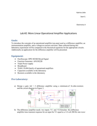
  • 1. Katrina Little Sean S. Electronics II Lab #2: More Linear Operational Amplifier Applications Goals: To introduce the concepts of an operational amplifier (op-amp) used as a difference amplifier, an instrumentation amplifier, and a voltage-to-current converter. Data collected during this laboratory experiment will be compared to the theoretical equations for the appropriate circuits. Additionally an application for the difference amplifier will be presented. Equipment:  Oscilloscope: DPO 4034B Mixed Signal  Function Generator: AFG3022B  Triple Power supply  Breadboard  TL081-TL084 family of operational amplifiers  Capacitors available in the laboratory  Resistors available in the laboratory Pre-Laboratory: a) Design a gain Ad = 2 difference amplifier using a minimum of 1k-ohm resistors and the circuit diagram in Figure 3. b) The difference amplifier needs two inputs V1 and V2.Simulate this difference amplifier time transient response for an input for V1 equal to a 1.0 volt 200 Hz sine wave
  • 2. and for V2 equal to a 1.0 volt 200 Hz sine wave but 180 degrees out of phase with the V1. c) Plot the input voltages as well as the output voltage as a function of time. d) Repeat steps b and c but this time set the phase difference between V1 and V2 to 0 degrees. e) Repeat steps a, b, c, and d for a gain Ad = 4 difference amplifier.
  • 3. f) Design a gain Ad = 2 instrumentation amplifier using a minimum of 1k-ohm resistors and the circuit diagram in Figure 5. g) The instrumentation amplifier needs two inputs V1 and V2. Simulate this instrumentation amplifier time transient response for an input for V1 equal to a 1.0 volt 200 Hz sine wave and for V2 equal to a 1.0 volt 200 Hz sine wave but 180 degrees out of phase with the V1. h) Plot the input voltages as well as the output voltage as a function of time.
  • 4. i) Repeat steps g and h but this time set the phase difference between V1 and V2 to 0 degrees. j) Repeat steps f, g, h, and i for a gain Ad = 4 instrumentation amplifier. k) Design a voltage-to-current converter that produces an output of 1ma for every volt of input using a minimum of 1k-ohm resistors and the circuit diagram in Figure 6. l) Simulate the voltage to converter designed in step k for V2 = 3 volts and Vin = 2 volts. m) Vary V3 between 1 volt and 5 volts and plot Iout versus V3.
  • 5. Procedure: General Setup: 1. Record the model and serial number of the scope, power supply, multimeter and function generator used in laboratory experiment. 2. Download the datasheet for the op-amp used. This will be needed to obtain the pin-out of the op-amp used. When comparing datasheet data values to experimental data use the typical values in the datasheet if given. 3. Make sure that the power supply to the op-amp is correctly wired as not to apply the incorrect polarity to the op-amp. 4. Initially set +Vcc = 15 volts and -Vcc to -15 volts 5. When measuring any values make sure to measure all inputs as well as the output of the circuit. Do not rely on the values indicated on the instruments. Always measure all signal values.
  • 6. 6. The output impedance of the signal generator is 50 ohms. If the generator is connected to a load other than 50 ohms, the displayed Amplitude, Offset, and High/Low values will be different than what is selected on the generator. Usually a factor of 2 larger. 7. Before turning any power on double check the wiring to make sure that it is correct. 8. Measure all resistors that are used in the amplifier circuits using the multimeter and record these values. 9. Use all measured values to determine experimental results such as gain and current. 10. Comparing data means to calculate the percent difference between two values. For example, theoretical values versus measured values. 11. Comparing data graphically means to plot the data on the same plot to see how the data overlaps. 12. Obtain the pin out for the 2N2222 transistor Difference Amplifier: 1. Using the parts kit in the lab, design the difference amplifier of Figure 3 with a gain of Ad = 2 using 1k ohm resistors for R1 and R3. R4 = R2 = 2kΩ 2. Measure with the multimeter the actual resistance values. R1 = 0.987 kΩ R2 = 1.956 kΩ R3 = 0.991 kΩ R4 = 1.959 kΩ 3. Compute Acm and Ad using Equations (12) and (14). Acm = -.0047 * ½ Ad = 1.9794 4. Also calculate the CMMR using Equation (15). CMRR = 52.423 5. Build the gain of Ad = 2 difference amplifier. 6. Setting V1 = V2 = 20 volt peak-to-peak 200 Hz sine wave measure Vout. 7. Calculate from step 6 Acm = Vout / V1. Acm = 24/19.2 = 1.25 8. Varying the frequency of the function generator from 100 Hz to 100 kHz repeat steps 6, and 7. Use measured values at frequencies of 1X, 2X and 5X for each decade.
  • 7.
  • 8.
  • 9.
  • 10. Input of 20Vpp f (Hz) Vout (V) Acm=(Vout/V1) 100 1.079 mV 0.00005297 200 1.081 mV 0.00005406 500 1.083 mV 0.00005416 1 K 1.099 mV 0.00005497 2K 1.135 mV 0.0000568 5K 1.238 mV 0.00006198 10K 1.735 mV 0.00008708 20K 2.283mV 0.0001146 50K 5.431mV 0.002742 100K 6.546 mV 0.0003274
  • 11. 9. Setting V1 = 1 volt peak-to-peak 200 Hz sine wave and V2 = -V1. To generate V2 = -V1, build an inverting amplifier1 with a gain equal to –1. Apply the function generator to V1 input to the difference amplifier and to the inverting amplifier. The output of the inverter is now equal to -V1 and can be applied to V2 input to the difference amplifier. 10. Measure Vout from step 9. Vout = 3.72 V 11. Calculate Ad from step 9 (Ad = Vout / (2*V1). Ad =2.214 12. Using Equation (15) calculate the CMRR from Acm from Step 7 and Ad from Step 10. CMRR = 4.9654 13. Compare step 12 to step 4. 14. Discuss in the laboratory report the result of step 13.
  • 12.
  • 13.
  • 14. 15. Varying the frequency of the function generator from 100 Hz to 100 kHz repeat steps 9, 10, and 11. Use measured values at frequencies of 1X, 2X and 5X for each decade. Input of 1Vpp f(Hz) Vout (V) Ad = Vout /(2xV1) 100 3.992 1.99972 200 3.998 2.010055 500 3.999 1.99993 1 K 3.999 2.00041 2K 3.999 1.99994 5K 3.98 2.001215 10K 3.987 2.001874 20K 3.998 2.00868 50K 3.99 1.99499 100K 3.967 1.98614 16. From steps 14, 15 calculate CMRR as a function of frequency. f (Hz) Acm=(Vout/V1) Ad = Vout /(2xV1) CMRR 100 0.00005297 1.99972 91.5278 200 0.00005406 2.010055 91.4066 500 0.00005416 1.99993 91.3467 1 K 0.00005497 2.00041 91.2199 2K 0.0000568 1.99994 91.2178 5K 0.00006198 2.001215 90.1808 10K 0.00008708 2.001874 87.2304 20K 0.0001146 2.00868 84.8745 50K 0.002742 1.99499 77.2375
  • 15. 100K 0.0003274 1.98614 55.6586 17. From steps 14, 15 and 16 plot Acm, Ad, CMRR as a function of Frequency. 18. Decrease the value of R4 by 15 % to 20 %. Add a 10K ohm variable resistor in series with this new value of R4. One side of the variable resistor to R4 and the middle connection to ground. See Figure 7. 19. Setting V1 = V2 = 20 volt peak-to-peak 200 Hz sine wave measure Vout. Adjust this variable resistor (potentiometer) to yield the smallest value for Vout. Adjust R4 to best match R2 (This is the optimum setting). Vout = 1.9V 20. Repeat steps 6,7, 9, 10, and 11 with this optimum setting for the potentiometer. Acm = 1.9 0 10 20 30 40 50 60 70 80 90 100 Acm=(Vout/V1) Ad = Vout /(2xV1) CMRR
  • 16. Vout = 3.76V Vin = 960 mV 21. Build a gain of Ad = 4 difference amplifier. 22. Repeat steps 6, 7, 9, 10, and 11 for the difference amplifier of step 21. 23. Build the test circuit shown in Figure 8 with a gain of Ad = 4 for the difference amplifier. This allows for two voltage sources to be applied to V1 and V2 of the difference amplifier. The op-amp circuit of U2 inverts V1 adding 180 degree phase shift. U1 and U3 are unity gain summers, summing V2 and V1 to produce two signals into the difference amplifier: Vout(U1) = - V1 - V2 (36) Vout(U3) = +V1 - V2 (37) 24. Set V1 to a 0.5 volt peak-to-peak 200 Hz sine wave. Also set V2 to a 0.5 volt peak-to- peak 20 Hz sine wave. 25. Measure and record with oscilloscope the outputs U1 and U2 op-amp stages. U1 Vout = 900mV U2 Vout = 500mV 26. Measure and record Vout with the Oscilloscope. Vout = 3.54V
  • 17. 27. Discuss in the laboratory report the results of steps 25 and 26.
  • 18. Instrumentation Amplifier: 1. Using the parts kit in the lab, build the instrumentation amplifier of Figure 5 with a gain of Ad = 2 using 1k ohm resistors for R21, R3, and R7. 2. Measure with the multimeter the actual resistance values. R1 = .978 kΩ R2 = .978 kΩ R3 = .975 kΩ R4 = .987 kΩ R5 = .468 kΩ R6 = .467 kΩ R7 = .990 kΩ 3. Compute Acm and Ad using Equations (22) and (23). Ad = 2 Acm = 0 4. Also calculate the CMMR using Equation (15). CMMR = 5. Setting V1 = V2 = 20 volt peak-to-peak 200 Hz sine wave measure Vout. Vout = 128mV
  • 19. 6. Calculate from step 5 Acm = Vout / V1. Acm = 0.0003136 7. Setting V1 = 1 volt peak-to-peak 200 Hz sine wave and V2 = -V1. To generate V2 = -V1, build an inverting amplifier2 with a gain equal to -1. Apply the function generator to V1 input to the difference amplifier and to the inverting amplifier. The output of the inverter is now equal to -V1 and can be applied to V2 input to the difference amplifier. 8. Measure Vout from step 7. Vout = 3.96V 9. Calculate Ad from step 8 (Ad = Vout / (2*V1). Ad = 1.9975 10. Using Equation (24) calculate the CMRR from Acm from Step 6 and Ad from Step 9. CMMR = 96.082 dB 11. Compare step 10 to step 4. 12. Discuss in the laboratory report the result of step 11. 13. Varying the frequency of the function generator from 100 Hz to 100 kHz repeat steps 5, and 6. Use measured values at frequencies of 1X, 2X and 5X for each decade.
  • 20.
  • 21.
  • 22.
  • 23.
  • 24. 14. Varying the frequency of the function generator from 100 Hz to 100 kHz repeat steps 7, 8, and 9. Use measured values at frequencies of 1X, 2X and 5X for each decade. 15. From steps 13 and 14 calculate CMRR as a function of frequency. 16. From steps 13, 14, and 15 plot Acm, Ad, CMRR as a function of Frequency.
  • 25. Voltage to Current Converter: 1. Design and build the voltage to current converter given in Figure 6 for a conversion factor of 1milliamp of out for one volt of input. 2. Using a load resistance of RL = 1k ohms and V2 = 15 volts measure the voltage across R2 and RL for Vin = 1 volt VRL = 1.012V VR2 = .9997V 3. Compute the current in RL and R2 from step 2. IL = I2 = Vin/R2 = 1mA 4. Varying the input from 0 to 5 volts, repeat steps 2 and 3. Make sure there is at least 5 points measured per integer voltage value. 5. Plot IL versus Vin from step 4. Is the curve linear? 6. Setting Vin to 2 volts measure IL as a function of V2 with V2 varying from 1 volt to 5 volts.
  • 26. 7. Plot IL versus V2. 8. Setting Vin to 2 volts and V2 to 5 volts measure Vin with RL varying from 100 ohms to 2k ohms. Use at least 5 different resistor values for RL.
  • 27. 9. Plot IL versus RL.