1. Page 168
UNIT-6
DC Choppers
7.1 Introduction
• Chopper is a static device.
• A variable dc voltage is obtained from a constant dc voltage source.
• Also known as dc-to-dc converter.
• Widely used for motor control.
• Also used in regenerative braking.
• Thyristor converter offers greater efficiency, faster response, lower maintenance,
smaller size and smooth control.
Choppers are of Two Types
• Step-down choppers.
• Step-up choppers.
• In step down chopper output voltage is less than input voltage.
• In step up chopper output voltage is more than input voltage.
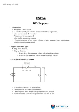
7.2 Principle of Step-down Chopper
V
i0
V0
Chopper
R
+
−
• A step-down chopper with resistive load.
• The thyristor in the circuit acts as a switch.
• When thyristor is ON, supply voltage appears across the load
• When thyristor is OFF, the voltage across the load will be zero.
www.getmyuni.com
2. Page 169
Vdc
v0
V
V/R
i0
Idc
t
t
tON
T
tOFF
verage value of output or load voltage.
verage value of output or load current.
Time interval for which SCR conducts.
Time interval for which SCR is OFF.
Period of switching
dc
dc
ON
OFF
ON OFF
V A
I A
t
t
T t t
=
=
=
=
= + = or chopping period.
1
Freq. of chopper switching or chopping freq.
f
T
= =
Average Output Voltage
.
duty cycle
ON
dc
ON OFF
ON
dc
ON
t
V V
t t
t
V V V d
T
t
but d
t
=
+
= =
= =
2
0
Average Output Current
RMS value of output voltage
1 ON
dc
dc
ON
dc
t
O o
V
I
R
t
V V
I d
R T R
V v dt
T
=
= =
= ∫
2
0
2
But during ,
Therefore RMS output voltage
1
.
.
ON
ON o
t
O
ON
O ON
O
t v V
V V dt
T
t
V
V t V
T T
V d V
=
=
= =
=
∫
www.getmyuni.com
3. Page 170
Methods of Control
• The output dc voltage can be varied by the following methods.
– Pulse width modulation control or constant frequency operation.
– Variable frequency control.
–
Pulse Width Modulation
• tON is varied keeping chopping frequency ‘f’ & chopping period ‘T’ constant.
• Output voltage is varied by varying the ON time tON
V0
V
V
V0
t
t
tON
tON tOFF
tOFF
T
Variable Frequency Control
• Chopping frequency ‘f’ is varied keeping either tON or tOFF constant.
• To obtain full output voltage range, frequency has to be varied over a wide range.
• This method produces harmonics in the output and for large tOFF load current may
become discontinuous
2
2
Output power
But
Output power
O O O
O
O
O
O
O
P V I
V
I
R
V
P
R
dV
P
R
=
=
∴
=
=
Effective input resistance of chopper
The output voltage can be varied by
varying the duty cycle.
i
dc
i
V
R
I
R
R
d
=
=
www.getmyuni.com
4. Page 171
v0
V
V
v0
t
t
tON
tON
T
T
tOFF
tOFF
7.2.1 Step-down Chopper with R-L Load
V
i0
V0
Chopper
R
L
FWD
E
+
−
• When chopper is ON, supply is connected across load.
• Current flows from supply to load.
• When chopper is OFF, load current continues to flow in the same direction
through FWD due to energy stored in inductor ‘L’.
• Load current can be continuous or discontinuous depending on the values of ‘L’
and duty cycle ‘d’
• For a continuous current operation, load current varies between two limits Imax
and Imin
• When current becomes equal to Imax the chopper is turned-off and it is turned-on
when current reduces to Imin.
www.getmyuni.com
6. Page 173
When Chopper is OFF
i0
R
L
E
( ) min
Taking Inverse Laplace Transform
1
This expression is valid for 0 ,
i.e., during the period chopper is ON.
At the instant the chopper is turned off,
load c
R R
t t
L L
O
ON
V E
i t e I e
R
t t
− −
−
= − +
≤ ≤
( ) max
urrent is O ON
i t I
=
( )
( ) ( ) ( )
( ) max
When Chopper is OFF 0
0
Talking Laplace transform
0 0
Redefining time origin we have at 0,
initial current 0
OFF
O
O
O O O
O
t t
di
Ri L E
dt
E
RI S L SI S i
S
t
i I
−
−
≤ ≤
= + +
= + − +
=
=
( )
( )
max
max
Taking Inverse Laplace Transform
1
O
R R
t t
L L
O
I E
I S
R R
S LS S
L L
E
i t I e e
R
− −
∴ = −
+ +
= − −
www.getmyuni.com
7. Page 174
( ) min
The expression is valid for 0 ,
i.e., during the period chopper is OFF
At the instant the chopper is turned ON or at
the end of the off period, the load current is
OFF
O OFF
t t
i t I
≤ ≤
=
( )
( )
min
max
max
max min
min
From equation
1
At ,
To Find &
1
R R
t t
L L
O
ON O
dRT dRT
L L
V E
i t e I e
R
t t dT i t I
V E
I e I e
I I
R
− −
− −
−
= − +
= = =
−
∴ = − +
( )
( )
( )
max
min
From equation
1
At ,
1
R R
t t
L L
O
OFF ON O
OFF
E
i t I e e
R
t t T t i t I
t t d T
− −
= − −
= = − =
= = −
( ) ( )
1 1
min max
min
max min
max
1
Substituting for in equation
1
we get,
1
1
d RT d RT
L L
dRT dRT
L L
dRT
L
RT
L
E
I I e e
R
I
V E
I e I e
R
V e E
I
R R
e
− −
− −
− −
−
−
∴ = − −
−
= − +
−
= −
−
( ) ( )
( )
max
1 1
min max
min
max min
Substituting for in equation
1
we get,
1
1
is known as the steady state ripple.
d RT d RT
L L
dRT
L
RT
L
I
E
I I e e
R
V e E
I
R R
e
I I
− −
− −
= − −
−
= −
−
−
www.getmyuni.com
8. Page 175
( )
max min
max min
Therefore peak-to-peak ripple current
Average output voltage
.
Average output current
2
dc
dc approx
I I I
V d V
I I
I
∆ = −
=
+
=
( )
( )
min max
min
max min
min
Assuming load current varies linearly
from to instantaneous
load current is given by
.
0
O ON
O
I I
I t
i I for t t dT
dT
I I
i I t
dT
∆
= + ≤ ≤
−
= +
( )
( )
( )
( )
( )
2
0
0
2
max min
min
0
2
min max min
2 2
max min
min
0
RMS value of load current
1
1
2
1
dT
O RMS
dT
O RMS
dT
O RMS
I i dt
dT
I I t
I I dt
dT dT
I I I t
I I
I I t dt
dT dT dT
=
−
= +
−
−
= + +
∫
∫
∫
( )
( )
( )
1
2 2
max min
2
min min max min
3
Effective input resistance is
CH
CH O RMS
i
S
I I
I d I I I I
I d I
V
R
I
−
= + + −
=
=
www.getmyuni.com
9. Page 176
7.3 Principle of Step-up Chopper
+
−
VO
V
Chopper
C
L
O
A
D
D
L
I
+ −
• Step-up chopper is used to obtain a load voltage higher than the input voltage V.
• The values of L and C are chosen depending upon the requirement of output
voltage and current.
• When the chopper is ON, the inductor L is connected across the supply.
• The inductor current ‘I’ rises and the inductor stores energy during the ON time of
the chopper, tON.
• When the chopper is off, the inductor current I is forced to flow through the diode
D and load for a period, tOFF.
• The current tends to decrease resulting in reversing the polarity of induced EMF
in L.
• Therefore voltage across load is given by
• A large capacitor ‘C’ connected across the load, will provide a continuous output
voltage .
• Diode D prevents any current flow from capacitor to the source.
• Step up choppers are used for regenerative braking of dc motors.
Where
Average source current
S
S dc
i
dc
I
I dI
V
R
dI
=
=
∴ =
. .,
O O
dI
V V L i e V V
dt
= + >
www.getmyuni.com
10. Page 177
(i) Expression For Output Voltage
Assume the average inductor current to be
during ON and OFF time of Chopper.
Voltage across inductor
Therefore energy stored in inductor
= . .
Where
When Chopper
period of chopper.
is ON
ON
ON
I
L V
V I t
t ON
=
=
( )
(energy is supplied by inductor to load)
Voltage across
Energy supplied by inductor
where period of Chopper.
Neg
When Chopper
lecting losses, energy stored in inductor
is OFF
O
O OFF
OFF
L V V
L V V It
t OFF
L
= −
= −
=
= energy supplied by inductor L
( )
[ ]
Where
T = Chopping period or period
of switching.
ON O OFF
ON OFF
O
OFF
O
ON
VIt V V It
V t t
V
t
T
V V
T t
∴ = −
+
=
=
−
1
1
1
1
Where duty cyle
ON OFF
O
ON
O
ON
T t t
V V
t
T
V V
d
t
d
T
= +
=
−
∴ =
−
= =
www.getmyuni.com
11. Page 178
Performance Parameters
• The thyristor requires a certain minimum time to turn ON and turn OFF.
• Duty cycle d can be varied only between a min. & max. value, limiting the min. and
max. value of the output voltage.
• Ripple in the load current depends inversely on the chopping frequency, f.
• To reduce the load ripple current, frequency should be as high as possible.
Problem
1. A Chopper circuit is operating on TRC at a frequency of 2 kHz on a 460 V supply. If
the load voltage is 350 volts, calculate the conduction period of the thyristor in each
cycle.
Solution:
Problem
2. Input to the step up chopper is 200 V. The output required is 600 V. If the conducting
time of thyristor is 200 µsec. Compute
– Chopping frequency,
– If the pulse width is halved for constant frequency of operation, find the new
output voltage.
Solution:
3
460 V, = 350 V, f = 2 kHz
1
Chopping period
1
0.5 sec
2 10
Output voltage
dc
ON
dc
V V
T
f
T m
t
V V
T
−
=
=
= =
×
=
3
Conduction period of thyristor
0.5 10 350
460
0.38 msec
dc
ON
ON
ON
T V
t
V
t
t
−
×
=
× ×
=
=
6
200 , 200 , 600
600 200
200 10
Solving for
300
ON dc
dc
ON
V V t s V V
T
V V
T t
T
T
T
T s
µ
µ
−
= = =
=
−
=
− ×
=
www.getmyuni.com
12. Page 179
Problem
3. A dc chopper has a resistive load of 20Ω and input voltage VS = 220V. When chopper
is ON, its voltage drop is 1.5 volts and chopping frequency is 10 kHz. If the duty cycle is
80%, determine the average output voltage and the chopper on time.
Solution:
6
6
Chopping frequency
1
1
3.33
300 10
Pulse width is halved
200 10
100
2
ON
f
T
f KHz
t s
µ
−
−
=
= =
×
×
∴ = =
( )
6
6
Frequencyis constant
3.33
1
300
Output voltage =
300 10
200 300 Volts
300 100 10
ON
f KHz
T s
f
T
V
T t
µ
−
−
∴ =
= =
∴
−
×
= =
−
( )
( )
220 , 20 , 10
0.80
= Voltage drop across chopper = 1.5 volts
Average output voltage
0.80 220 1.5 174.8 Volts
S
ON
ch
ON
dc S ch
dc
V V R f kHz
t
d
T
V
t
V V V
T
V
= = Ω =
= =
= −
= − =
www.getmyuni.com
13. Page 180
Problem
4. In a dc chopper, the average load current is 30 Amps, chopping frequency is 250 Hz,
supply voltage is 110 volts. Calculate the ON and OFF periods of the chopper if the load
resistance is 2 ohms.
Solution:
Problem
5. A dc chopper in figure has a resistive load of R = 10Ω and input voltage of V = 200
V. When chopper is ON, its voltage drop is 2 V and the chopping frequency is 1 kHz. If
the duty cycle is 60%, determine
– Average output voltage
3
3
3
3
Chopper ON time,
1
Chopping period,
1
0.1 10 secs 100 µsecs
10 10
Chopper ON time,
0.80 0.1 10
0.08 10 80 µsecs
ON
ON
ON
ON
t dT
T
f
T
t dT
t
t
−
−
−
=
=
= = × =
×
=
= × ×
= × =
3
30 , 250 , 110 , 2
1 1
Chopping period, 4 10 4 msecs
250
&
30 2
0.545
110
dc
dc
dc dc
dc
dc
I Amps f Hz V V R
T
f
V
I V dV
R
dV
I
R
I R
d
V
−
= = = = Ω
= = = × =
= =
∴ =
×
= = =
3
3 3
3
Chopper ON period,
0.545 4 10 2.18 msecs
Chopper OFF period,
4 10 2.18 10
1.82 10 1.82 msec
ON
OFF ON
OFF
OFF
t dT
t T t
t
t
−
− −
−
= = × × =
= −
= × − ×
= × =
www.getmyuni.com
14. Page 181
– RMS value of output voltage
– Effective input resistance of chopper
– Chopper efficiency.
V
i0
Chopper
+
−
R v0
Solution:
( )
[ ]
( )
( )
Average output voltage
0.60 200 2 118.8 Volts
RMS value of output voltage
0.6 200 2 153.37 Volts
dc ch
dc
O ch
O
V d V V
V
V d V V
V
= −
= − =
= −
= − =
( )
2
2
0
0 0
Effective input resistance of chopper is
118.8
11.88 Amps
10
200
16.83
11.88
Output power is
1 1
i
S dc
dc
dc
i
S dc
dT dT
ch
O
V V
R
I I
V
I
R
V V
R
I I
V V
v
P dt dt
T R T R
= =
= = =
= = = = Ω
−
= =
∫ ∫
( )
[ ]
( )
2
2
0
0
0.6 200 2
2352.24 watts
10
Input power,
1
1
ch
O
O
dT
i O
dT
ch
O
d V V
P
R
P
P Vi dt
T
V V V
P dt
T R
−
=
−
= =
=
−
=
∫
∫
www.getmyuni.com
15. Page 182
7.4 Classification of Choppers
Choppers are classified as
• Class A Chopper
• Class B Chopper
• Class C Chopper
• Class D Chopper
• Class E Chopper
1. Class A Chopper
V
Chopper
FWD
+
−
v0
v0
i0
i0
L
O
A
D
V
• When chopper is ON, supply voltage V is connected across the load.
• When chopper is OFF, vO = 0 and the load current continues to flow in the same
direction through the FWD.
• The average values of output voltage and current are always positive.
• Class A Chopper is a first quadrant chopper .
• Class A Chopper is a step-down chopper in which power always flows form source to
load.
• It is used to control the speed of dc motor.
• The output current equations obtained in step down chopper with R-L load can be
used to study the performance of Class A Chopper.
Output current
Thyristor
gate pulse
Output voltage
ig
i0
v0
t
t
t
tON
T
CH ON
FWD Conducts
www.getmyuni.com
16. Page 183
2. Class B Chopper
V
Chopper
+
−
v0
v0
−i0
i0
L
E
R
D
• When chopper is ON, E drives a current through L and R in a direction opposite to
that shown in figure.
• During the ON period of the chopper, the inductance L stores energy.
• When Chopper is OFF, diode D conducts, and part of the energy stored in inductor L
is returned to the supply.
• Average output voltage is positive.
• Average output current is negative.
• Therefore Class B Chopper operates in second quadrant.
• In this chopper, power flows from load to source.
• Class B Chopper is used for regenerative braking of dc motor.
• Class B Chopper is a step-up chopper.
Output current
D
conducts Chopper
conducts
Thyristor
gate pulse
Output voltage
ig
i0
v0
t
t
t
Imin
Imax
T
tON
tOFF
www.getmyuni.com
17. Page 184
(i) Expression for Output Current
( ) min
For the initial condition i.e.,
During the interval diode 'D' conduc
at 0
The solution of the ab
ts
voltage equation
ove equation is obtained
along similar lines as in s
is given by
O
O
O
Ldi
V Ri E
dt
i t I t
= + +
= =
tep-down chopper
with R-L load
( )
( ) ( )
min
max
max min
During the interval chopper is ON voltage
equation is g
1 0
At
1
0
iven by
OFF OFF
R R
t t
L L
O OFF
OFF O
R R
t t
L L
O
O
V E
i t e I e t t
R
t t i t I
V E
I e I e
R
Ldi
Ri E
dt
− −
− −
−
∴ = − + < <
= =
−
= − +
= + +
( )
( )
( )
max
max
min
min max
Redefining the time origin, at 0
The solution for the stated initial condition is
1 0
At
1
ON ON
O
R R
t t
L L
O ON
ON O
R R
t t
L L
t i t I
E
i t I e e t t
R
t t i t I
E
I I e e
R
− −
− −
= =
= − − < <
= =
∴ = − −
www.getmyuni.com
18. Page 185
3. Class C Chopper
V
Chopper
+
−
v0
D1
D2
CH2
CH1
v0
i0
i0
L
E
R
• Class C Chopper is a combination of Class A and Class B Choppers.
• For first quadrant operation, CH1 is ON or D2 conducts.
• For second quadrant operation, CH2 is ON or D1 conducts.
• When CH1 is ON, the load current is positive.
• The output voltage is equal to ‘V’ & the load receives power from the source.
• When CH1 is turned OFF, energy stored in inductance L forces current to flow
through the diode D2 and the output voltage is zero.
• Current continues to flow in positive direction.
• When CH2 is triggered, the voltage E forces current to flow in opposite direction
through L and CH2 .
• The output voltage is zero.
• On turning OFF CH2 , the energy stored in the inductance drives current through
diode D1 and the supply
• Output voltage is V, the input current becomes negative and power flows from load to
source.
• Average output voltage is positive
• Average output current can take both positive and negative values.
• Choppers CH1 & CH2 should not be turned ON simultaneously as it would result in
short circuiting the supply.
• Class C Chopper can be used both for dc motor control and regenerative braking of
dc motor.
• Class C Chopper can be used as a step-up or step-down chopper.
www.getmyuni.com
19. Page 186
Gate pulse
of CH2
Gate pulse
of CH1
Output current
Output voltage
ig1
ig2
i0
V0
t
t
t
t
D1 D1
D2 D2
CH1 CH2 CH1 CH2
ON ON ON ON
4. Class D Chopper
V
+ −
v0
D2
D1 CH2
CH1
v0
i0
L E
R i0
• Class D is a two quadrant chopper.
• When both CH1 and CH2 are triggered simultaneously, the output voltage vO = V
and output current flows through the load.
• When CH1 and CH2 are turned OFF, the load current continues to flow in the same
direction through load, D1 and D2 , due to the energy stored in the inductor L.
• Output voltage vO = - V .
• Average load voltage is positive if chopper ON time is more than the OFF time
• Average output voltage becomes negative if tON < tOFF .
• Hence the direction of load current is always positive but load voltage can be positive
or negative.
www.getmyuni.com
20. Page 187
Gate pulse
of CH2
Gate pulse
of CH1
Output current
Output voltage
Average v0
ig1
ig2
i0
v0
V
t
t
t
t
CH ,CH
ON
1 2 D1,D2 Conducting
Gate pulse
of CH2
Gate pulse
of CH1
Output current
Output voltage
Average v0
ig1
ig2
i0
v0
V
t
t
t
t
CH
CH
1
2
D , D
1 2
5. Class E Chopper
V
v0
i0
L E
R
CH2 CH4
D2 D4
D1 D3
CH1 CH3
+ −
www.getmyuni.com
21. Page 188
Four Quadrant Operation
v0
i0
CH - CH ON
CH - D Conducts
1 4
4 2
D D
2 3
- Conducts
CH - D Conducts
4 2
CH - CH ON
CH - D Conducts
3 2
2 4
CH - D Conducts
D - D Conducts
2 4
1 4
• Class E is a four quadrant chopper
• When CH1 and CH4 are triggered, output current iO flows in positive direction
through CH1 and CH4, and with output voltage vO = V.
• This gives the first quadrant operation.
• When both CH1 and CH4 are OFF, the energy stored in the inductor L drives iO
through D2 and D3 in the same direction, but output voltage vO = -V.
• Therefore the chopper operates in the fourth quadrant.
• When CH2 and CH3 are triggered, the load current iO flows in opposite direction &
output voltage vO = -V.
• Since both iO and vO are negative, the chopper operates in third quadrant.
• When both CH2 and CH3 are OFF, the load current iO continues to flow in the same
direction D1 and D4 and the output voltage vO = V.
• Therefore the chopper operates in second quadrant as vO is positive but iO is negative.
Effect Of Source & Load Inductance
• The source inductance should be as small as possible to limit the transient voltage.
• Also source inductance may cause commutation problem for the chopper.
• Usually an input filter is used to overcome the problem of source inductance.
• The load ripple current is inversely proportional to load inductance and chopping
frequency.
• Peak load current depends on load inductance.
• To limit the load ripple current, a smoothing inductor is connected in series with the
load.
7. 5 Impulse Commutated Chopper
• Impulse commutated choppers are widely used in high power circuits where load
fluctuation is not large.
• This chopper is also known as
– Parallel capacitor turn-off chopper
– Voltage commutated chopper
www.getmyuni.com
22. Page 189
– Classical chopper.
L
O
A
D
L
C
IL
LS
VS
+
_
+
_
T2
T1
D1
a
b
iC
iT1
vO
+
_
FWD
• To start the circuit, capacitor ‘C’ is initially charged with polarity (with plate ‘a’
positive) by triggering the thyristor T2.
• Capacitor ‘C’ gets charged through VS, C, T2 and load.
• As the charging current decays to zero thyristor T2 will be turned-off.
• With capacitor charged with plate ‘a’ positive the circuit is ready for operation.
• Assume that the load current remains constant during the commutation process.
• For convenience the chopper operation is divided into five modes.
• Mode-1
• Mode-2
• Mode-3
• Mode-4
• Mode-5
Mode-1 Operation
L
O
A
D
L
C
IL
LS
VS
+
_
+
_
T1
D1
VC iC
• Thyristor T1 is fired at t = 0.
• The supply voltage comes across the load.
• Load current IL flows through T1 and load.
• At the same time capacitor discharges through T1, D1, L1, & ‘C’ and the capacitor
reverses its voltage.
• This reverse voltage on capacitor is held constant by diode D1.
www.getmyuni.com
23. Page 190
Mode-2 Operation
L
O
A
D
C
LS
VS
+
_
+
_
T2
VC
IL
IL
• Thyristor T2 is now fired to commutate thyristor T1.
• When T2 is ON capacitor voltage reverse biases T1 and turns if off.
• The capacitor discharges through the load from –V to 0.
• Discharge time is known as circuit turn-off time
• Capacitor recharges back to the supply voltage (with plate ‘a’ positive).
• This time is called the recharging time and is given by
• The total time required for the capacitor to discharge and recharge is called the
commutation time and it is given by
• At the end of Mode-2 capacitor has recharged to VS and the freewheeling diode starts
conducting.
( )
( )
Capacitor Discharge Current
sin
1
Where
& Capacitor Voltage
cos
C
C
C
i t V t
L
LC
V t V t
ω
ω
ω
=
=
=
C
Circuit turn-off time is given by
W here is load current.
t depends on load current, it must be designed
for the worst case condition which occur at the
maximum value of load current and mini
C
C
L
L
V C
t
I
I
×
=
mum
value of capacitor voltage.
www.getmyuni.com
24. Page 191
Mode-3 Operation
L
O
A
D
C
LS
VS
+
_
+
_
T2
VS
FWD
IL
IL
• FWD starts conducting and the load current decays.
• The energy stored in source inductance LS is transferred to capacitor.
• Hence capacitor charges to a voltage higher than supply voltage, T2
naturally turns off.
Mode-4 Operation
L
O
A
D
C
LS
VS
+
_
+
_
D1
L
FWD
IL
VC
• Capacitor has been overcharged i.e. its voltage is above supply voltage.
• Capacitor starts discharging in reverse direction.
• Hence capacitor current becomes negative.
• The capacitor discharges through LS, VS, FWD, D1 and L.
( )
The instantaneous capacitor voltage is
sin
Where
1
S
C S L S
S
S
L
V t V I t
C
L C
ω
ω
= +
=
www.getmyuni.com
25. Page 192
• When this current reduces to zero D1 will stop conducting and the capacitor voltage
will be same as the supply voltage.
Mode-5 Operation
L
O
A
D
IL
FWD
• Both thyristors are off and the load current flows through the FWD.
• This mode will end once thyristor T1 is fired.
Capacitor Current
IL
t
t
Ip Current through T1
ic
0
Ip
iT1
0
IL
t
t
t
Voltage across T1
Output Voltage
Capacitor Voltage
tc
td
vT1
Vc
0
vo
Vs c
+V
Vs
vc
Vc
-Vc
www.getmyuni.com
26. Disadvantages
• A starting circuit is required and the starting circuit should be such that it triggers
thyristor T2 first.
• Load voltage jumps to almost twice the supply voltage when the commutation is
initiated.
• The discharging and charging time of commutation capacitor are dependent on the
load current and this limits high frequency operation, especially at low load current.
• Chopper cannot be tested without connecting load.
Thyristor T1 has to carry load current as well as resonant current resulting in increasing its
peak current rating.
Recommended questions:
1. Explain the principle of operation of a chopper. Briefly explain time-ratio control and
PWM as applied to chopper
2. Explain the working of step down shopper. Determine its performance factors, VA, Vo
rms, efficiency and Ri the effective input resistane
3. Explain the working of step done chopper for RLE load. Obtain the expressions for
minimum load current I1max load current I2, peak – peak load ripple current di avg value
of load current Ia, the rms load current Io and Ri.
4. Give the classification of stem down converters. Explain with the help of circuit diagram
one-quadrant and four quadrant converters.
5. The step down chopper has a resistive load of R=10ohm and the input voltage is
Vs=220V. When the converter switch remain ON its voltage drop is Vch=2V and the
chopping frequency is 1 KHz. If the duty cycle is 50% determine a) the avg output
voltage VA, b) the rms output voltage Vo c) the converter efficiency d) the effective input
resistance Ri of the converter.
6. Explain the working of step-up chopper. Determine its performance factors.
www.getmyuni.com