SlideShare a Scribd company logo
1 of 7
Q. What is CAD ?
Ans. The process of constructing the drawings on the computer screen with the
help of specially developed softwares and hardwares is called Computer Aided
Drafting.
Q. Name various softwares used for CAD ?
Ans. Various softwares used for CAD are AutoCAD, Pro/ENGINEER, NX
Unigraphics, IronCAD, Catia, SOLIDEDGE, SOLIDWORKS, 3Ds Max and Visio.
Q. What are advantages of CAD ?
Ans. CAD offer following advantages
1. Accuracy: CAD helps to achieve very high degree of accuracy that is
impossible to achieve manually. For example, a line 22.532 mm long or an angle
of 53.27 can be precisely drawn in CAD software.
2. Speed: With sufficient practice, a user can create drawings speedily. Similar
objects can be copied or mirrored or arrayed which saves time required for
duplication. Automatic hatching, texting and dimensioning save time.
3. Easy Editing: Drawings once constructed can be easily edited or modified as
and when needed. Component drawings from one drawing file can be inserted in
another drawing file.
4. Space Effectiveness: A computer can store several thousand drawing files over
a long period of time. Equal no. of drawing sheets, drawn manually, will need a
big godown to store.
5. Standard libraries: CAD softwares have libraries containing drawings of
standard parts, such as gears, valves, pulleys, electrical and electronic
components, civil and architectural components that can be directly used.
6. Scaling: A drawing can be enlarged or reduced by any scale factor.
Dimensions change automatically. Further printing can be made to any scale.
7. Better visualization: Use of different colours helps avoiding confusion. A 3D
view of the object can be easily created to boost imagination.
8. Freedom from using drawing instruments: A simple Cad system needs a
computer with a mouse and a keyboard to draw. The draftsman need not use
bulky drawing instruments like drawing board, drafter, set square etc.
What are limitations of CAD ?
Ans. CAD has following limitations:
1. 32 bit computer is necessary because of large amount of memory and time.
3. Skill and judgment are required to prepare the drawing.
4. It requires huge investment.
2. The size of the software package is large.
What are main components of CAD ?
Ans. Main components of CAD are:
1. Title Bar: The colour strip displayed at the top of the AutoCAD window is called
the title bar. In the title bar the file name is indicated within [ ].
2. Menu Bar: The menu bar, located below the title bar, provides pull down
menus from which one can choose commands.
3. Tool Bar: There are many toolbars on the screen like draw tool bar, edit tool
bar etc. Each tool bar contains number of buttons, from which one can activate
command by clicking the button.
4. Status Bar: The status bar located at the bottom of the screen shows the
coordinates of the screen cursor as well as the current setting of various Autocad
program.
5. Command Window: The command window is one component of autocad that
does not have an equivalent in most other windows programs. One can activate
any autocad command by typing the command and pressing enter.
6. Document Window: The document window or drawing area, occupies most of
the screen. This is the area where one can actually creat the drawing.
Write any five draw commands used in CAD ?
Ans. Some important draw commands are : LINE (L), PLINE (polyline) (PL),
POINT (PO), POLYGON (POL), RECTANG (rectangle)(rec), ARC (A),
CIRCLE(C), SPLINE(SPL), ELLIPSE (EL), HATCH (H), MTEXT(multiline text) (t
or mt), XLINE (xl), RAY
Write any five edit commands used in CAD ?
Ans. Some important edit commands are : ERASE(e), COPY(co or cp), MIRROR
(mi), OFFSET (o), ARRAY (ar), MOVE (m), ROTATE (ro), SCALE (sc), TRIM (tr),
EXTEND (ex), BREAK (br), JOIN (j), CHAMFER (cha), FILLET (f), EXPLODE(x),
LENGTHEN (len)
Write any five standard tool bar commands used in CAD ?
Ans. Some important standard tool bar commands are :NEW, OPEN, SAVE,
UNDO (u), REDO,CUTCLIP, COPYCLIP, PROPERTIES(ch or mo or props),
MATCHPROP(match properties) (ma), PAN (p), ZOOM(z)
Write any five commands used for dimensioning in CAD ?
Ans. Some important dimensioning commands are :DIMALIGNED (dal or dimali),
DIMRADIUS (dra or dimrad), DIMDIAMETER (ddi or dimdia), DIMANGULAR (dan
or dimang), LEADER(ql)
Write commands to draw a regular pentagon of sides 30 mm?
Ans. POLYGON
enter no. of sides 5
specify center of polygon or [Edge] E
specify first end point of edge 10,10
specify second end point of edge 40,10
Write commands to draw a right cylinder of base 40 mm and height 60 mm?
Ans. CYLINDER
specify center point for base of cylinder [0.0.0] 30,30,0
specify radius for base of cylinder or [DIAMETER] D
specify diameter for base of cylinder 40
specify height of cylinder or center of other end 60
Explain various commands of drawing circles in AUTOCAD system?
Ans. various commands of drawing circles in AUTOCAD system are as follows
1. Using centre and radius:
The command for drawing a circle having centre at (30, 31) and radius 20 are as
follows.
Command :Circle
3P/ 2p /TTR /< center point> :30, 31
Diameter /<radius> :20
Using three given point (3P) :
The command for drawing circle with three known given points on the circum-
ference of the circle is as follows
Command :Circle
3P/2P/TTR <center point> :3P
First point :5, 20
Second point :3, 30
Third point :6, 25
write a short note on polygon command in Auto CAD ?
Ans. The polygon command of Auto CAD draw regular 2D polygons with 3 to
1024 sides following three methods can be used to draw any polygon by using
polygon command.
Inscribing polygon in a circle :-
Command for inscribing a polygon of 5sides in a circle with centre of (30, 30) and
radius 20 units is as follows
Command :polygon
Number of sides :5
Edge < centre of polygon > : 30, 30
Inscribed in a circle <circumscribed about circle (I / C) :I
Radius of circle :20
Circumscribe a polygon of 5 sides about a circle
Command :polygon
Number of sides :5
Edge < centre of polygon > : 30, 30
Inscribed in a circle <circumscribed about circle (I / C) :C
Radius of circle :20
Using edge method: - A regular polygon can be drawn by defining end point of an
edge of the polygon. Commands are as follows
Command : polygon
No. of sides : 8
Edge/ <centre of polygon> :E
First end point of edge :10,10
Second end point of edge :@20,0

More Related Content

What's hot

Projection of solids
Projection of solidsProjection of solids
Projection of solids
Sumit Chandak
 
Hermite bicubic-surface-patch
Hermite bicubic-surface-patchHermite bicubic-surface-patch
Hermite bicubic-surface-patch
Rohit Gothwal
 

What's hot (20)

Projection of solids
Projection of solidsProjection of solids
Projection of solids
 
Isometric Projection
Isometric ProjectionIsometric Projection
Isometric Projection
 
Engineering drawing
Engineering  drawing Engineering  drawing
Engineering drawing
 
Development of surfaces of solids
Development of surfaces of solidsDevelopment of surfaces of solids
Development of surfaces of solids
 
Projection of solids
Projection of solidsProjection of solids
Projection of solids
 
AUTOCAD PPT
AUTOCAD PPTAUTOCAD PPT
AUTOCAD PPT
 
Engineering Graphics-Lines
Engineering Graphics-LinesEngineering Graphics-Lines
Engineering Graphics-Lines
 
Curves2
Curves2Curves2
Curves2
 
Engineering graphics
Engineering graphicsEngineering graphics
Engineering graphics
 
Projection of lines(new)
Projection of lines(new)Projection of lines(new)
Projection of lines(new)
 
Commands in AutoCAD
Commands in AutoCADCommands in AutoCAD
Commands in AutoCAD
 
Introduction to CATIA
Introduction to CATIAIntroduction to CATIA
Introduction to CATIA
 
Engineering Curves
Engineering CurvesEngineering Curves
Engineering Curves
 
Auto cad
Auto cadAuto cad
Auto cad
 
Projection of points
Projection of pointsProjection of points
Projection of points
 
Cad notes
Cad notesCad notes
Cad notes
 
solidworks
solidworkssolidworks
solidworks
 
Sections of Solids
Sections of SolidsSections of Solids
Sections of Solids
 
Projection of Lines
Projection of LinesProjection of Lines
Projection of Lines
 
Hermite bicubic-surface-patch
Hermite bicubic-surface-patchHermite bicubic-surface-patch
Hermite bicubic-surface-patch
 

Similar to CAD - ENGINEERING DRAWING - RGPV,BHOPAL

RCB_16T3_AB2_ID063_AADIL
RCB_16T3_AB2_ID063_AADILRCB_16T3_AB2_ID063_AADIL
RCB_16T3_AB2_ID063_AADIL
Aadil Sukry
 
Autocad civil project file
Autocad civil project fileAutocad civil project file
Autocad civil project file
naveen899
 

Similar to CAD - ENGINEERING DRAWING - RGPV,BHOPAL (20)

Autocad
AutocadAutocad
Autocad
 
Cad
CadCad
Cad
 
my ppt for autocad &autocad electrical
my ppt for autocad &autocad electricalmy ppt for autocad &autocad electrical
my ppt for autocad &autocad electrical
 
CAD
CADCAD
CAD
 
rohit raj.pptx
rohit raj.pptxrohit raj.pptx
rohit raj.pptx
 
Practical work 3
Practical work 3Practical work 3
Practical work 3
 
autocad.pptx
autocad.pptxautocad.pptx
autocad.pptx
 
Auto-CAD
Auto-CADAuto-CAD
Auto-CAD
 
Aragaw Gebremedhin auto cad lecture notes
Aragaw Gebremedhin auto cad lecture notesAragaw Gebremedhin auto cad lecture notes
Aragaw Gebremedhin auto cad lecture notes
 
RCB_16T3_AB2_ID063_AADIL
RCB_16T3_AB2_ID063_AADILRCB_16T3_AB2_ID063_AADIL
RCB_16T3_AB2_ID063_AADIL
 
CAD CAM Lab MANNUAL Dr.BRAU.pdf
CAD CAM Lab MANNUAL Dr.BRAU.pdfCAD CAM Lab MANNUAL Dr.BRAU.pdf
CAD CAM Lab MANNUAL Dr.BRAU.pdf
 
Basic_Introduction_to_AUTOCAD.ppt
Basic_Introduction_to_AUTOCAD.pptBasic_Introduction_to_AUTOCAD.ppt
Basic_Introduction_to_AUTOCAD.ppt
 
Cad
CadCad
Cad
 
CAD Lab model viva questions
CAD Lab model viva questions CAD Lab model viva questions
CAD Lab model viva questions
 
AUTO CADD PPT.pptx
AUTO CADD PPT.pptxAUTO CADD PPT.pptx
AUTO CADD PPT.pptx
 
autocad.ppt
autocad.pptautocad.ppt
autocad.ppt
 
DEMO PRESENTATION.pptx
DEMO PRESENTATION.pptxDEMO PRESENTATION.pptx
DEMO PRESENTATION.pptx
 
Autocad civil project file
Autocad civil project fileAutocad civil project file
Autocad civil project file
 
Civil project .ppt
Civil project .pptCivil project .ppt
Civil project .ppt
 
Auto Cad Course at MUCET, Khairpur
Auto Cad Course at MUCET, KhairpurAuto Cad Course at MUCET, Khairpur
Auto Cad Course at MUCET, Khairpur
 

More from Abhishek Kandare

More from Abhishek Kandare (12)

Swot becomes swoc
Swot becomes swocSwot becomes swoc
Swot becomes swoc
 
Decision making - ims davv
Decision making - ims davv Decision making - ims davv
Decision making - ims davv
 
Development of surfaces of solids -ENGINEERING DRAWING - RGPV,BHOPAL
Development of surfaces of solids -ENGINEERING DRAWING - RGPV,BHOPALDevelopment of surfaces of solids -ENGINEERING DRAWING - RGPV,BHOPAL
Development of surfaces of solids -ENGINEERING DRAWING - RGPV,BHOPAL
 
Important qUESTIONS ENGINEERING DRAWING
Important qUESTIONS ENGINEERING DRAWINGImportant qUESTIONS ENGINEERING DRAWING
Important qUESTIONS ENGINEERING DRAWING
 
Curve1- ENGINEERING DRAWING - RGPV,BHOPAL
Curve1- ENGINEERING DRAWING - RGPV,BHOPALCurve1- ENGINEERING DRAWING - RGPV,BHOPAL
Curve1- ENGINEERING DRAWING - RGPV,BHOPAL
 
Intersection - ENGINEERING DRAWING
Intersection - ENGINEERING DRAWINGIntersection - ENGINEERING DRAWING
Intersection - ENGINEERING DRAWING
 
Curves2 -ENGINEERING DRAWING - RGPV,BHOPAL
Curves2 -ENGINEERING DRAWING - RGPV,BHOPALCurves2 -ENGINEERING DRAWING - RGPV,BHOPAL
Curves2 -ENGINEERING DRAWING - RGPV,BHOPAL
 
Isometric - ENGINEERING DRAWING/GRAPHICS
Isometric - ENGINEERING DRAWING/GRAPHICSIsometric - ENGINEERING DRAWING/GRAPHICS
Isometric - ENGINEERING DRAWING/GRAPHICS
 
Ortographic projection - ENGINEERING DRAWING/GRAPHICS
Ortographic projection - ENGINEERING DRAWING/GRAPHICSOrtographic projection - ENGINEERING DRAWING/GRAPHICS
Ortographic projection - ENGINEERING DRAWING/GRAPHICS
 
Projection of solids - ENGINEERING DRAWING/GRAPHICS
Projection of solids - ENGINEERING DRAWING/GRAPHICSProjection of solids - ENGINEERING DRAWING/GRAPHICS
Projection of solids - ENGINEERING DRAWING/GRAPHICS
 
Section of solids - ENGINEERING DRAWING/GRAPHICS
Section of solids - ENGINEERING DRAWING/GRAPHICSSection of solids - ENGINEERING DRAWING/GRAPHICS
Section of solids - ENGINEERING DRAWING/GRAPHICS
 
Scales - ENGINEERING DRAWING/GRAPHICS
Scales - ENGINEERING DRAWING/GRAPHICSScales - ENGINEERING DRAWING/GRAPHICS
Scales - ENGINEERING DRAWING/GRAPHICS
 

Recently uploaded

Cara Menggugurkan Sperma Yang Masuk Rahim Biyar Tidak Hamil
Cara Menggugurkan Sperma Yang Masuk Rahim Biyar Tidak HamilCara Menggugurkan Sperma Yang Masuk Rahim Biyar Tidak Hamil
Cara Menggugurkan Sperma Yang Masuk Rahim Biyar Tidak Hamil
Cara Menggugurkan Kandungan 087776558899
 
Query optimization and processing for advanced database systems
Query optimization and processing for advanced database systemsQuery optimization and processing for advanced database systems
Query optimization and processing for advanced database systems
meharikiros2
 
1_Introduction + EAM Vocabulary + how to navigate in EAM.pdf
1_Introduction + EAM Vocabulary + how to navigate in EAM.pdf1_Introduction + EAM Vocabulary + how to navigate in EAM.pdf
1_Introduction + EAM Vocabulary + how to navigate in EAM.pdf
AldoGarca30
 
Kuwait City MTP kit ((+919101817206)) Buy Abortion Pills Kuwait
Kuwait City MTP kit ((+919101817206)) Buy Abortion Pills KuwaitKuwait City MTP kit ((+919101817206)) Buy Abortion Pills Kuwait
Kuwait City MTP kit ((+919101817206)) Buy Abortion Pills Kuwait
jaanualu31
 
XXXXXXXXXXXXXXXXXXXXXXXXXXXXXXXXXXXXXXXXXXXXXXXXXXXX
XXXXXXXXXXXXXXXXXXXXXXXXXXXXXXXXXXXXXXXXXXXXXXXXXXXXXXXXXXXXXXXXXXXXXXXXXXXXXXXXXXXXXXXXXXXXXXXXXXXXXXXX
XXXXXXXXXXXXXXXXXXXXXXXXXXXXXXXXXXXXXXXXXXXXXXXXXXXX
ssuser89054b
 

Recently uploaded (20)

Electromagnetic relays used for power system .pptx
Electromagnetic relays used for power system .pptxElectromagnetic relays used for power system .pptx
Electromagnetic relays used for power system .pptx
 
HOA1&2 - Module 3 - PREHISTORCI ARCHITECTURE OF KERALA.pptx
HOA1&2 - Module 3 - PREHISTORCI ARCHITECTURE OF KERALA.pptxHOA1&2 - Module 3 - PREHISTORCI ARCHITECTURE OF KERALA.pptx
HOA1&2 - Module 3 - PREHISTORCI ARCHITECTURE OF KERALA.pptx
 
UNIT 4 PTRP final Convergence in probability.pptx
UNIT 4 PTRP final Convergence in probability.pptxUNIT 4 PTRP final Convergence in probability.pptx
UNIT 4 PTRP final Convergence in probability.pptx
 
Online food ordering system project report.pdf
Online food ordering system project report.pdfOnline food ordering system project report.pdf
Online food ordering system project report.pdf
 
S1S2 B.Arch MGU - HOA1&2 Module 3 -Temple Architecture of Kerala.pptx
S1S2 B.Arch MGU - HOA1&2 Module 3 -Temple Architecture of Kerala.pptxS1S2 B.Arch MGU - HOA1&2 Module 3 -Temple Architecture of Kerala.pptx
S1S2 B.Arch MGU - HOA1&2 Module 3 -Temple Architecture of Kerala.pptx
 
fitting shop and tools used in fitting shop .ppt
fitting shop and tools used in fitting shop .pptfitting shop and tools used in fitting shop .ppt
fitting shop and tools used in fitting shop .ppt
 
Cara Menggugurkan Sperma Yang Masuk Rahim Biyar Tidak Hamil
Cara Menggugurkan Sperma Yang Masuk Rahim Biyar Tidak HamilCara Menggugurkan Sperma Yang Masuk Rahim Biyar Tidak Hamil
Cara Menggugurkan Sperma Yang Masuk Rahim Biyar Tidak Hamil
 
Path loss model, OKUMURA Model, Hata Model
Path loss model, OKUMURA Model, Hata ModelPath loss model, OKUMURA Model, Hata Model
Path loss model, OKUMURA Model, Hata Model
 
8th International Conference on Soft Computing, Mathematics and Control (SMC ...
8th International Conference on Soft Computing, Mathematics and Control (SMC ...8th International Conference on Soft Computing, Mathematics and Control (SMC ...
8th International Conference on Soft Computing, Mathematics and Control (SMC ...
 
COST-EFFETIVE and Energy Efficient BUILDINGS ptx
COST-EFFETIVE  and Energy Efficient BUILDINGS ptxCOST-EFFETIVE  and Energy Efficient BUILDINGS ptx
COST-EFFETIVE and Energy Efficient BUILDINGS ptx
 
Query optimization and processing for advanced database systems
Query optimization and processing for advanced database systemsQuery optimization and processing for advanced database systems
Query optimization and processing for advanced database systems
 
Introduction to Artificial Intelligence ( AI)
Introduction to Artificial Intelligence ( AI)Introduction to Artificial Intelligence ( AI)
Introduction to Artificial Intelligence ( AI)
 
Memory Interfacing of 8086 with DMA 8257
Memory Interfacing of 8086 with DMA 8257Memory Interfacing of 8086 with DMA 8257
Memory Interfacing of 8086 with DMA 8257
 
1_Introduction + EAM Vocabulary + how to navigate in EAM.pdf
1_Introduction + EAM Vocabulary + how to navigate in EAM.pdf1_Introduction + EAM Vocabulary + how to navigate in EAM.pdf
1_Introduction + EAM Vocabulary + how to navigate in EAM.pdf
 
Unit 4_Part 1 CSE2001 Exception Handling and Function Template and Class Temp...
Unit 4_Part 1 CSE2001 Exception Handling and Function Template and Class Temp...Unit 4_Part 1 CSE2001 Exception Handling and Function Template and Class Temp...
Unit 4_Part 1 CSE2001 Exception Handling and Function Template and Class Temp...
 
Kuwait City MTP kit ((+919101817206)) Buy Abortion Pills Kuwait
Kuwait City MTP kit ((+919101817206)) Buy Abortion Pills KuwaitKuwait City MTP kit ((+919101817206)) Buy Abortion Pills Kuwait
Kuwait City MTP kit ((+919101817206)) Buy Abortion Pills Kuwait
 
Convergence of Robotics and Gen AI offers excellent opportunities for Entrepr...
Convergence of Robotics and Gen AI offers excellent opportunities for Entrepr...Convergence of Robotics and Gen AI offers excellent opportunities for Entrepr...
Convergence of Robotics and Gen AI offers excellent opportunities for Entrepr...
 
XXXXXXXXXXXXXXXXXXXXXXXXXXXXXXXXXXXXXXXXXXXXXXXXXXXX
XXXXXXXXXXXXXXXXXXXXXXXXXXXXXXXXXXXXXXXXXXXXXXXXXXXXXXXXXXXXXXXXXXXXXXXXXXXXXXXXXXXXXXXXXXXXXXXXXXXXXXXX
XXXXXXXXXXXXXXXXXXXXXXXXXXXXXXXXXXXXXXXXXXXXXXXXXXXX
 
Computer Networks Basics of Network Devices
Computer Networks  Basics of Network DevicesComputer Networks  Basics of Network Devices
Computer Networks Basics of Network Devices
 
Linux Systems Programming: Inter Process Communication (IPC) using Pipes
Linux Systems Programming: Inter Process Communication (IPC) using PipesLinux Systems Programming: Inter Process Communication (IPC) using Pipes
Linux Systems Programming: Inter Process Communication (IPC) using Pipes
 

CAD - ENGINEERING DRAWING - RGPV,BHOPAL

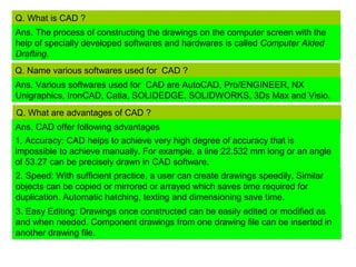
  • 1. Q. What is CAD ? Ans. The process of constructing the drawings on the computer screen with the help of specially developed softwares and hardwares is called Computer Aided Drafting. Q. Name various softwares used for CAD ? Ans. Various softwares used for CAD are AutoCAD, Pro/ENGINEER, NX Unigraphics, IronCAD, Catia, SOLIDEDGE, SOLIDWORKS, 3Ds Max and Visio. Q. What are advantages of CAD ? Ans. CAD offer following advantages 1. Accuracy: CAD helps to achieve very high degree of accuracy that is impossible to achieve manually. For example, a line 22.532 mm long or an angle of 53.27 can be precisely drawn in CAD software. 2. Speed: With sufficient practice, a user can create drawings speedily. Similar objects can be copied or mirrored or arrayed which saves time required for duplication. Automatic hatching, texting and dimensioning save time. 3. Easy Editing: Drawings once constructed can be easily edited or modified as and when needed. Component drawings from one drawing file can be inserted in another drawing file.
  • 2. 4. Space Effectiveness: A computer can store several thousand drawing files over a long period of time. Equal no. of drawing sheets, drawn manually, will need a big godown to store. 5. Standard libraries: CAD softwares have libraries containing drawings of standard parts, such as gears, valves, pulleys, electrical and electronic components, civil and architectural components that can be directly used. 6. Scaling: A drawing can be enlarged or reduced by any scale factor. Dimensions change automatically. Further printing can be made to any scale. 7. Better visualization: Use of different colours helps avoiding confusion. A 3D view of the object can be easily created to boost imagination. 8. Freedom from using drawing instruments: A simple Cad system needs a computer with a mouse and a keyboard to draw. The draftsman need not use bulky drawing instruments like drawing board, drafter, set square etc. What are limitations of CAD ? Ans. CAD has following limitations: 1. 32 bit computer is necessary because of large amount of memory and time. 3. Skill and judgment are required to prepare the drawing. 4. It requires huge investment. 2. The size of the software package is large.
  • 3. What are main components of CAD ? Ans. Main components of CAD are: 1. Title Bar: The colour strip displayed at the top of the AutoCAD window is called the title bar. In the title bar the file name is indicated within [ ]. 2. Menu Bar: The menu bar, located below the title bar, provides pull down menus from which one can choose commands. 3. Tool Bar: There are many toolbars on the screen like draw tool bar, edit tool bar etc. Each tool bar contains number of buttons, from which one can activate command by clicking the button. 4. Status Bar: The status bar located at the bottom of the screen shows the coordinates of the screen cursor as well as the current setting of various Autocad program. 5. Command Window: The command window is one component of autocad that does not have an equivalent in most other windows programs. One can activate any autocad command by typing the command and pressing enter. 6. Document Window: The document window or drawing area, occupies most of the screen. This is the area where one can actually creat the drawing.
  • 4. Write any five draw commands used in CAD ? Ans. Some important draw commands are : LINE (L), PLINE (polyline) (PL), POINT (PO), POLYGON (POL), RECTANG (rectangle)(rec), ARC (A), CIRCLE(C), SPLINE(SPL), ELLIPSE (EL), HATCH (H), MTEXT(multiline text) (t or mt), XLINE (xl), RAY Write any five edit commands used in CAD ? Ans. Some important edit commands are : ERASE(e), COPY(co or cp), MIRROR (mi), OFFSET (o), ARRAY (ar), MOVE (m), ROTATE (ro), SCALE (sc), TRIM (tr), EXTEND (ex), BREAK (br), JOIN (j), CHAMFER (cha), FILLET (f), EXPLODE(x), LENGTHEN (len) Write any five standard tool bar commands used in CAD ? Ans. Some important standard tool bar commands are :NEW, OPEN, SAVE, UNDO (u), REDO,CUTCLIP, COPYCLIP, PROPERTIES(ch or mo or props), MATCHPROP(match properties) (ma), PAN (p), ZOOM(z) Write any five commands used for dimensioning in CAD ? Ans. Some important dimensioning commands are :DIMALIGNED (dal or dimali), DIMRADIUS (dra or dimrad), DIMDIAMETER (ddi or dimdia), DIMANGULAR (dan or dimang), LEADER(ql)
  • 5. Write commands to draw a regular pentagon of sides 30 mm? Ans. POLYGON enter no. of sides 5 specify center of polygon or [Edge] E specify first end point of edge 10,10 specify second end point of edge 40,10 Write commands to draw a right cylinder of base 40 mm and height 60 mm? Ans. CYLINDER specify center point for base of cylinder [0.0.0] 30,30,0 specify radius for base of cylinder or [DIAMETER] D specify diameter for base of cylinder 40 specify height of cylinder or center of other end 60 Explain various commands of drawing circles in AUTOCAD system? Ans. various commands of drawing circles in AUTOCAD system are as follows 1. Using centre and radius: The command for drawing a circle having centre at (30, 31) and radius 20 are as follows. Command :Circle 3P/ 2p /TTR /< center point> :30, 31 Diameter /<radius> :20
  • 6. Using three given point (3P) : The command for drawing circle with three known given points on the circum- ference of the circle is as follows Command :Circle 3P/2P/TTR <center point> :3P First point :5, 20 Second point :3, 30 Third point :6, 25 write a short note on polygon command in Auto CAD ? Ans. The polygon command of Auto CAD draw regular 2D polygons with 3 to 1024 sides following three methods can be used to draw any polygon by using polygon command. Inscribing polygon in a circle :- Command for inscribing a polygon of 5sides in a circle with centre of (30, 30) and radius 20 units is as follows Command :polygon Number of sides :5 Edge < centre of polygon > : 30, 30 Inscribed in a circle <circumscribed about circle (I / C) :I Radius of circle :20
  • 7. Circumscribe a polygon of 5 sides about a circle Command :polygon Number of sides :5 Edge < centre of polygon > : 30, 30 Inscribed in a circle <circumscribed about circle (I / C) :C Radius of circle :20 Using edge method: - A regular polygon can be drawn by defining end point of an edge of the polygon. Commands are as follows Command : polygon No. of sides : 8 Edge/ <centre of polygon> :E First end point of edge :10,10 Second end point of edge :@20,0