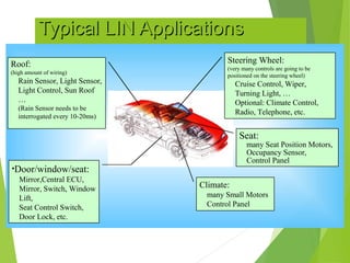
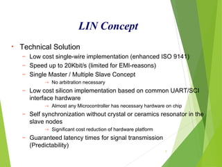
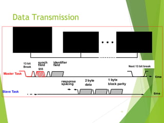
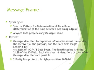
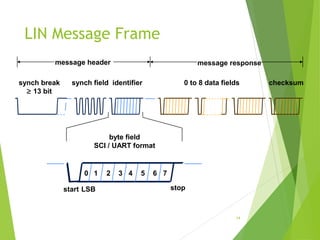
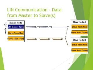
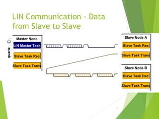
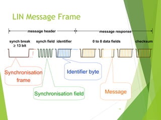
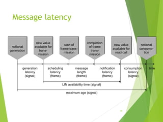
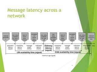
3. The Need for LIN
3
(a) Multimedia applications, calling for protocols providing high
speed, high bandwidth, and even wireless interconnection,
like MOST, D2B, or Bluetooth;
(b) Emerging safety critical applications in chassis and power
train (x-by wire) calling for a fault tolerant, dependable
protocol,like TTP/C, byteflight, TT-CAN or others;
(c) Conventional body and power train applications, mainly using
CAN;
(d) Mechatronic type applications such as smart sensors and
actuator, or even complex ECUs with simple communications
needs, being addressed by low-end protocols like LIN, TTP/A,
J-1850, and quite a few other OEM or Tier-I in-house
protocols.
4. Typical LIN ApplicationsTypical LIN Applications
4
•Door/window/seat:
Mirror,Central ECU,
Mirror, Switch, Window
Lift,
Seat Control Switch,
Door Lock, etc.
Roof:
(high amount of wiring)
Rain Sensor, Light Sensor,
Light Control, Sun Roof
…
(Rain Sensor needs to be
interrogated every 10-20ms)
Seat:
many Seat Position Motors,
Occupancy Sensor,
Control Panel
Steering Wheel:
(very many controls are going to be
positioned on the steering wheel)
Cruise Control, Wiper,
Turning Light, …
Optional: Climate Control,
Radio, Telephone, etc.
Climate:
many Small Motors
Control Panel
5. 7
LIN Concept
• Technical Solution
– Low cost single-wire implementation (enhanced ISO 9141)
– Speed up to 20Kbit/s (limited for EMI-reasons)
– Single Master / Multiple Slave Concept
→ No arbitration necessary
– Low cost silicon implementation based on common UART/SCI
interface hardware
→ Almost any Microcontroller has necessary hardware on chip
– Self synchronization without crystal or ceramics resonator in the
slave nodes
→ Significant cost reduction of hardware platform
– Guaranteed latency times for signal transmission
(Predictability)
6. Master / Slave Protocol
Master
has control over the whole Bus and Protocol
The master controls which message at what time is
to be transferred over the bus. It also does the error
handling.
To accomplish this the master
sends Sync Break
sends Sync Byte
sends ID-Field
monitors Data Bytes and Check Byte, and evaluates them on
consistance
receives WakeUp Break from slave nodes when the bus is
inactive and they request some action.
serves as a reference with it’s clock base (stable clock
necessary)
8
7. Master/Slave Protocol
Slave
Is one of 2-16 Members on the Bus and receives or
transmits Data when an appropriate ID is sent by the
master.
Slave snoops for ID.
According to ID, slave determines what to do.
either receive data
or transmit data
or do nothing.
When transmitting the slave
sends 1, 2, 4, or 8 Data Bytes
sends Check-Byte
The node serving as a master can be slave, too!
9
8. Data Transmission
11
time
Master Task
time
Slave Task
next synch field
inter-frame
spacing
synch
field
2 byte 1 byte
response
spacing
identifier
field
block paritydata
master control unit
slave task
master task
slave control unit
slave task
slave control unit
slave task
polling
13 bit
Break
$55
Next 13 bit break
9. Message Frame
Synch Byte:
Specific Pattern for Determination of Time Base
(Determination of the time between two rising edges)
A Synch Byte precedes any Message Frame
ID-Field:
Message Identifier: Incorporates Information about the sender,
the receiver(s), the purpose, and the Data field length.
Length 6 Bit.
4 classes of 1/2/4/8 Data Bytes. The length coding is in the
2 LSB of the ID-Field. Each class has 16 Identifiers. A total of 64
Message Identifiers are possible.
2 Parity Bits protect this highly sensitive ID-Field.
12
10. Identifier
The identifier field is sent by the master node to all LIN nodes
This identifier normally contains one of 64 different values
and includes 2 parity bits in the 8 bit data
The identifier is normally associated with a collection of
signals that are subsequently transmitted on the LIN bus
In a specific case this can initiate SLEEP mode in the LIN slave
nodes – in this case no further data is transmitted on the LIN
bus
13
synch break
≥ 13 bit
synch field identifier
message header
11. LIN Message Frame
14
0 to 8 data fields checksum
message response
synch break
≥ 13 bit
synch field identifier
message header
byte field
SCI / UART format
start stop
0 1 2 3 4 5 6 7
LSB
12. LIN Communication - Data
from Slave to Master
15
data byte data byte checksum
synch fieldidentifier synch break
Slave Node
Slave Task Trans
Slave Task Rec
Master Node
LIN Master Task
Slave Task Trans
Slave Task Rec
quartz
• Single-master / multi-slave protocol
• Time triggered, no arbitration
• Identifier denotes message content, not physical address
• Multicast messages
• Baud rate synchronization through protocol
• Power saving sleep mode
13. LIN Communication - Data
from Master to Slave(s)
16
Master Node
LIN Master Task
Slave Task Trans
Slave Task Rec
quartz
Slave Node A
Slave Task Trans
Slave Task Rec
Slave Node B
Slave Task Trans
Slave Task Rec
14. LIN Communication - Data
from Slave to Slave
17
Slave Node A
Slave Task Trans
Slave Task Rec
Slave Node B
Slave Task Trans
Slave Task Rec
Master Node
LIN Master Task
Slave Task Trans
Slave Task Rec
quartz
15. LIN Message Frame
18
0 to 8 data fields checksum
message response
synch break
≥ 13 bit
synch field identifier
message header
Synchronisation
frame
Synchronisation field
Identifier byte
Message
16. Frame Synchronisation (1)
19
Initial conditions: +/- 4% baud rate accuracy relative the
transmitting source
A standard transmission of data will require matched send and
receiver baud rates
Stop bit
Start-Bit
Standard UART byte
A normal UART with <4% baud rate error
will read back the data correctly
17. Frame Synchronisation (2)
20
Initial conditions: +/- 15% baud rate accuracy relative the the LIN
master transmitting the synchronisation frame
A synch break must be at least 13 bit periods in duration to allow for
this initial variation in oscillator accuracy within the LIN slave
Start-Bit
Normal UART message
Master sends a break (13 bits period duration or more)
A slow LIN slave may see fewer bit periods
1 2 11
1 10 13
18. Bit-Synchronization
A start bit transition to a low logic level (dominant) indicates
a start of a byte, least significiant first and completing with a
logic high level (resessive) bit to indicate the STOP bit
21
Stop-BitStart-Bit
Data is sampled in the middle of the bit field:
Sample Clock
20. Bit-Synchronisation
23
Stop-BitStart-Bit
Sample Clock
After recognition of a Low level in the start bit, the data is sampled at a rate
16 times the bit rate expected. The middle 3 samples must all agree for an
error free reception of the data.
A stop bit is expected after 1 start bit and 8 data bits in a typical message
21. Taking account of Ground-Shift
24
The detection point for data transitions can be affected by voltage references. Ground shift
can change this reference by a significant amount, affecting the bit timing of the data
Data timing
Sensevoltage
Available bit sampling zone can reduce worst case bit width to around 40us at 20k baud
This affects the overall baud rate tolerance required for safe LIN communications
22. 25
LIN Physical Interface
VBAT
8...18V
GND
recessive
logic ‘1’
dominant
logic ‘0’
60%
40%
Bus Voltage
Time
UART
Rx
Tx
Electronic Control Unit
master: 1kΩ
slave: 30kΩ
Bus
controlled slope
~2V/µs
Example capacitances
master: 2.2nF
slave: 220pF
Note:
The LIN specification refers to the ECU connector voltages !
23. signal latencies
generation latency
the time between an event input (e.g. a button pressed) and the signal
being placed in a buffer, ready for transmission
consumption latency
the time from when a signal has been received from the network into a
buffer until it has been read into the subscribing application and some
action has taken place (e.g. a motor starts moving).
maximum age
This is the maximum allowed time between a user action in the
publishing node until the subscribing node is actually carrying out an
action.
27
24. Message latency
28
new value
available for
read call
completion
of frame
trans-
mission
start of
frame trans-
mission
new value
available for
trans-
mission
notional
generation
generation
latency
(signal)
notional
consump-
tion
timeconsumption
latency
(signal)
message
length
(frame)
scheduling
latency
(frame)
notification
latency
(frame)
LIN availability time (signal)
maximum age (signal)
25. Message latency across a
network
29
notional
generatio
n
new value
available
for trans-
mission
new value
available
for read
call
start of
frame
trans-
mission
completio
n of
frame
trans-
mission
generation
latency
(signal)
timeconsumption
latency
(signal)
message
length
(frame)
scheduling
latency
(frame)
notification
latency
(frame)
LIN availability time (signal)
maximum age (signal)
new
value
available
for trans-
mission
new value
available
for read
call
start of
frame
trans-
mission
completio
n of
frame
trans-
mission
message
length
(frame)
scheduling
latency
(frame)
notification
latency
(frame)
Gateway
latency
(signal)
CAN availability time (signal)
notional
consump-
tion
26. Variables Scheduling
30
Sub Schedule Table
Main
Schedule Table
Sub Schedule Table
Sub
Schedule Table
Alternate
Schedule Table
Msg A Msg EMsg AMsg DMsg AMsg CMsg B Msg B Msg F
Decision
Msg EMsg AMsg G Msg F