
Recommended
More Related Content
Similar to UNIT 2b.pptx
Similar to UNIT 2b.pptx (20)
Recently uploaded
Recently uploaded (20)
UNIT 2b.pptx
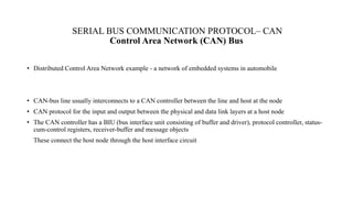
- 1. SERIAL BUS COMMUNICATION PROTOCOL– CAN Control Area Network (CAN) Bus • Distributed Control Area Network example - a network of embedded systems in automobile • CAN-bus line usually interconnects to a CAN controller between the line and host at the node • CAN protocol for the input and output between the physical and data link layers at a host node • The CAN controller has a BIU (bus interface unit consisting of buffer and driver), protocol controller, status- cum-control registers, receiver-buffer and message objects These connect the host node through the host interface circuit
- 3. CAN protocol • A CAN controller between the CAN line and the host node. • CAN controller ─BIU (Bus Interface Unit) consisting of a buffer and driver • Method for arbitration─ CSMA/AMP (Carrier Sense Multiple Access with Arbitration on Message Priority basis) Each Distributed Node Uses: • Twisted Pair Connection up to 40 m –for bi-directional data • Line, which pulls to Logic 1 through a resistor between the line and + 4.5V to +12V. : • Line Idle state Logic 1 (Recessive state) • Uses a buffer gate between an input pin and the CAN line • Detects Input Presence at the CAN line pulled down to dominant (active) state logic 0 (ground ~ 0V) by a sender to the CAN line • Uses a current driver between the output pin and CAN line and pulls line down to dominant (active) state logic 0 (ground ~ 0V) when sending to the CAN line
- 4. Standard CAN The meaning of the bit fields of Figure 2 are: SOF–The single dominant start of frame (SOF) bit marks the start of a message, and is used to synchronize the nodes on a bus after being idle. Identifier-The Standard CAN 11-bit identifier establishes the priority of the message. The lower the binary value, the higher its priority. RTR–The single remote transmission request (RTR) bit is dominant when information is required from another node. All nodes receive the request, but the identifier determines the specified node. The responding data is also received by all nodes and used by any node interested. In this way, all data being used in a system is uniform. IDE–A dominant single identifier extension (IDE) bit means that a standard CAN identifier with no extension is being transmitted. r0–Reserved bit (for possible use by future standard amendment).
- 5. • DLC–The 4-bit data length code (DLC) contains the number of bytes of data being transmitted. • Data–Up to 64 bits of application data may be transmitted. • CRC–The 16-bit (15 bits plus delimiter) cyclic redundancy check (CRC) contains the checksum (number of bits transmitted) of the preceding application data for error detection. • ACK–Every node receiving an accurate message overwrites this recessive bit in the original message with a dominate bit, indicating an error-free message has been sent. Should a receiving node detect an error and leave this bit recessive, it discards the message and the sending node repeats the message after rearbitration. In this way, each node acknowledges (ACK) the integrity of its data. ACK is 2 bits, one is the acknowledgment bit and the second is a delimiter. • EOF–This end-of-frame (EOF), 7-bit field marks the end of a CAN frame (message) and disables bitstuffing, indicating a stuffing error when dominant. When 5 bits of the same logic level occur in succession during normal operation, a bit of the opposite logic level is stuffed into the data.
- 6. Applications • The modern automobile may have as many as 70 electronic control units (ECU) for various subsystems. Some of these form independent subsystems, but communications among others are essential. A subsystem may need to control actuators or receive feedback from sensors. The CAN standard was devised to fill this need. • The CAN bus is also used as a fieldbus in general automation environments, primarily due to the low cost of some CAN controllers and processors.