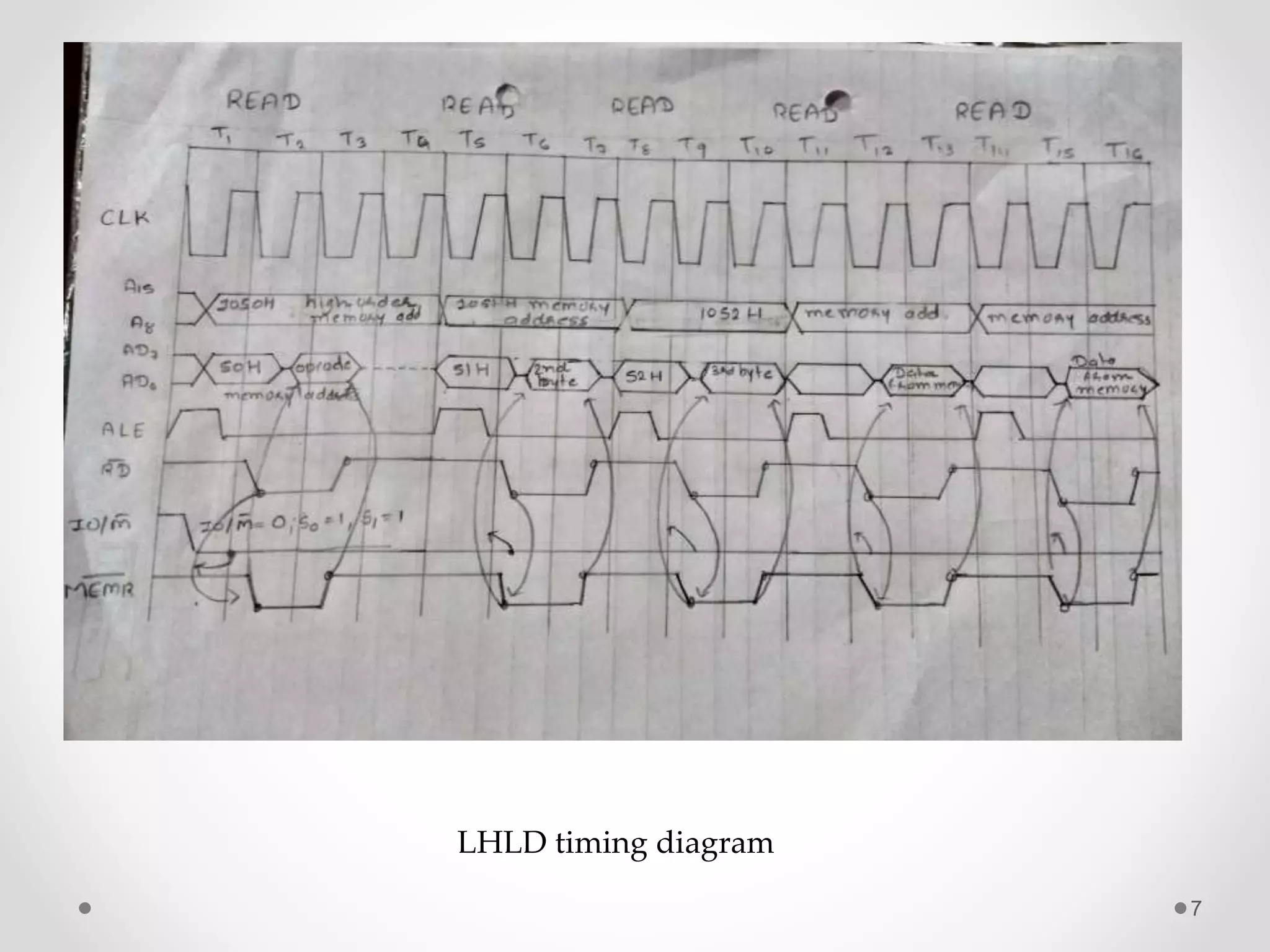
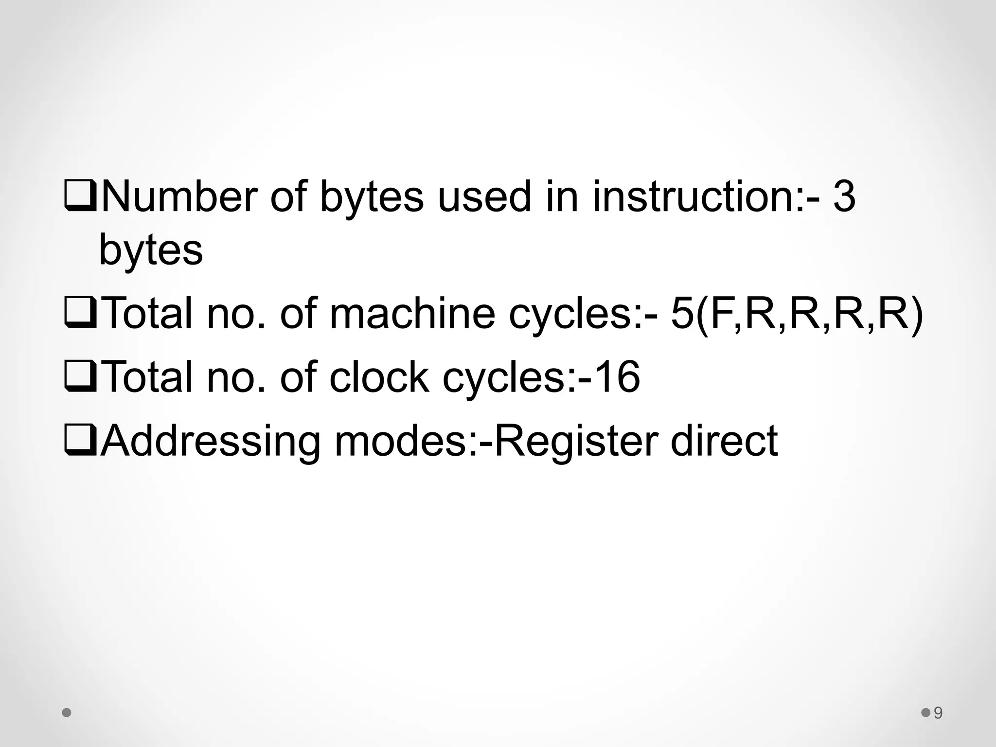
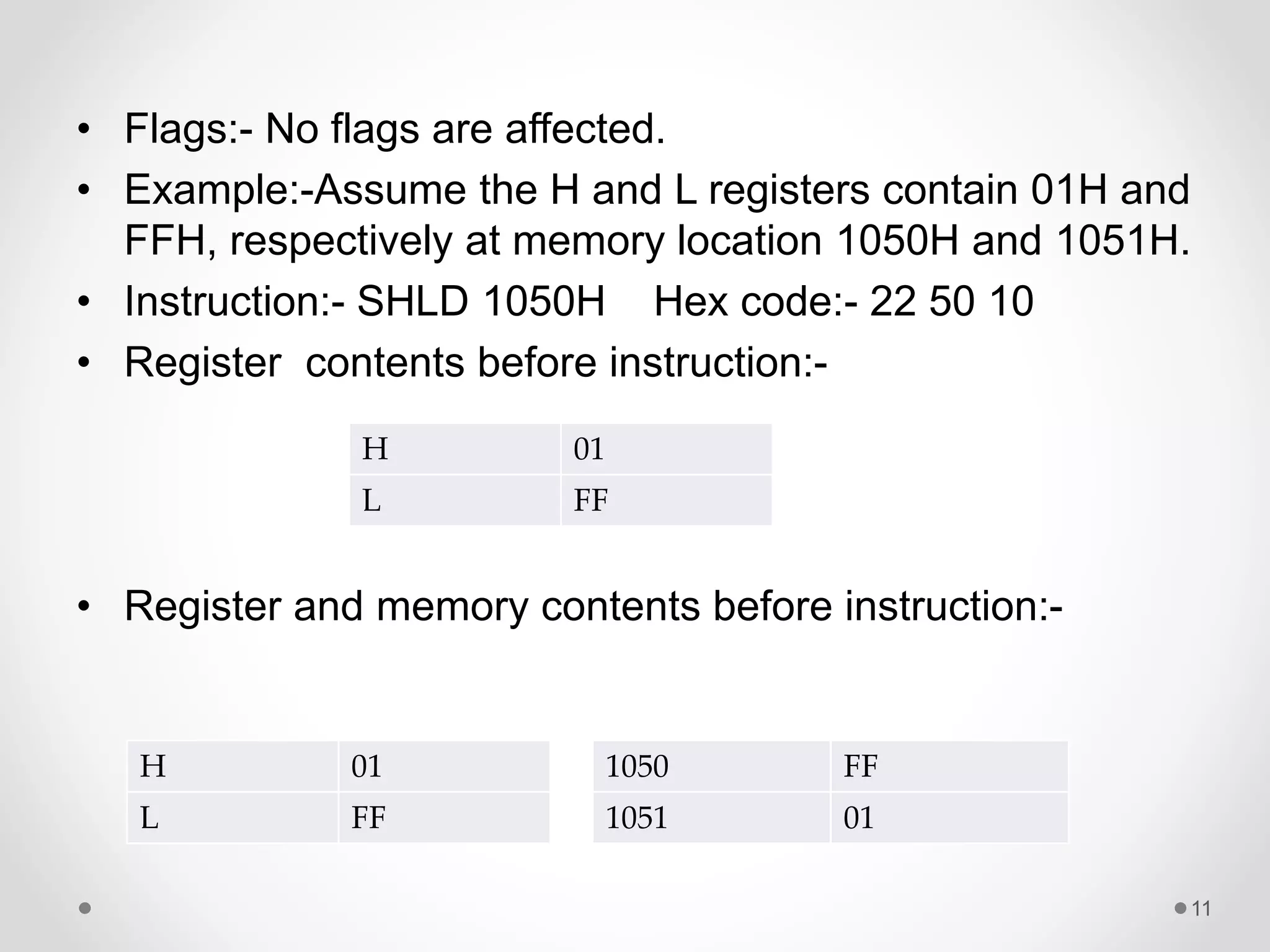
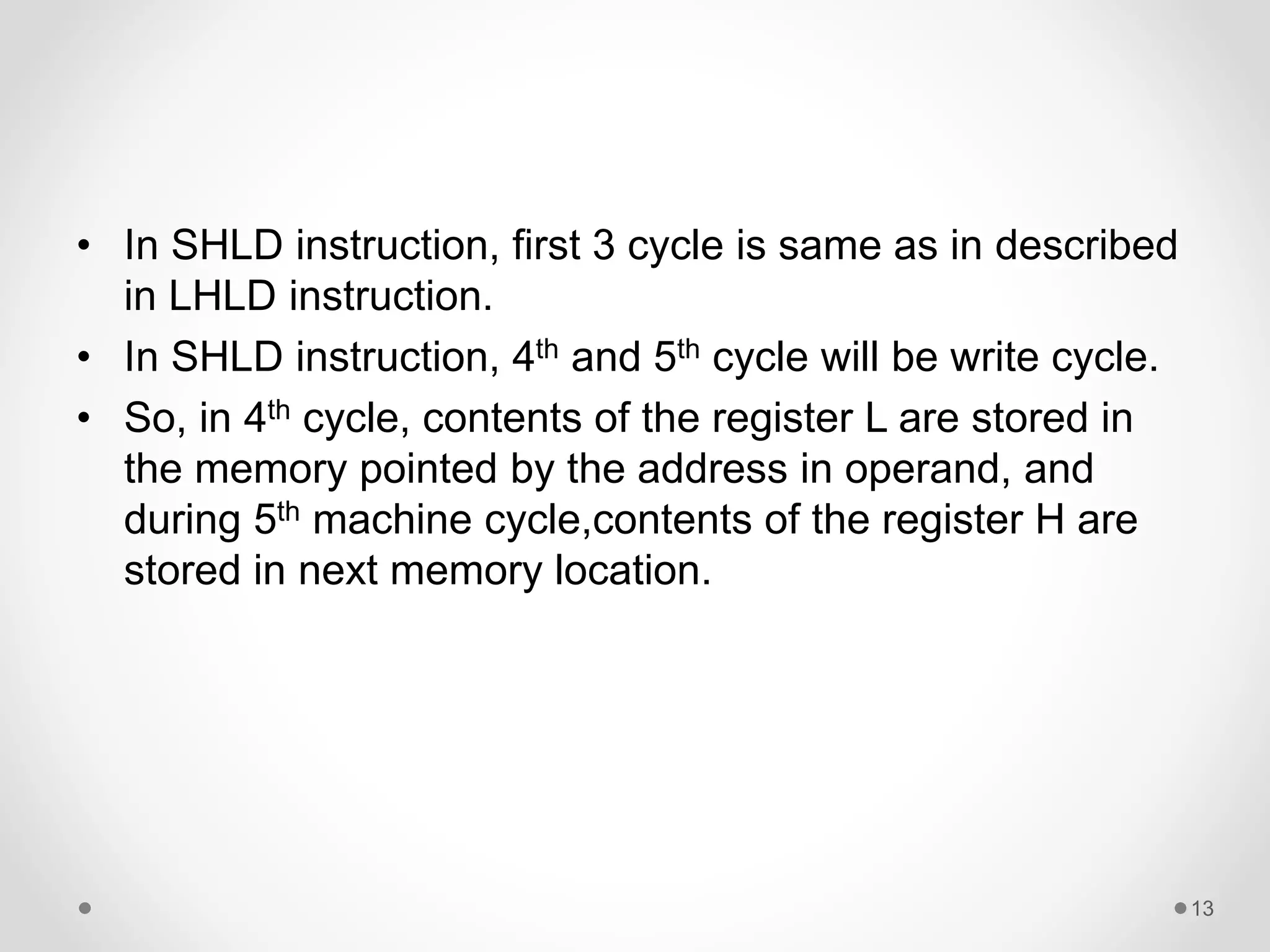
COMPUTER
ORGANISATION
• TOPIC:DATA TRANSFER
INSTRUCTIONS
• Group:- G2 BATCH:-B3
• MADE BY:15CP032-SIDDHAPURA ROMIL
15CP018-AHALPARA KEVAL
15CP033-KAVAIYA HIREN
1
8085 Microprocessor
2
• The microprocessor is a
programmable integrated
device that has computing and
decision making capability
similar to that CPU of a
computer.
• It is a multi-purpose,clock-
driven, register-based
electronic device.
LET’S BEGIN WITH MAIN DATA
TRANSFER INSTRUCTIONS
• One of the primarily functions of microprocessor is
copying data from source register to destination register.
• This copying function is labeled as data transfer
instructions.
• In fact, contents of the source are not transferred but are
copied into destination without modyfying the content of
source.
• The previous contents of destination are replaced by the
contents by the contents of the source.
• Several instruction are used to copy data which are
listed below:-
3
LIST OF DATA TRANSFER
INSTRUCTION
• MOV Rd,Rs:- Copies data from source register Rs to
destination register Rd.
• MVI R,8-bit:- Loads the 8-bit of the second byte into
the register specified.
• OUT 8-bit port address:- Sends the contents of the
accumulator (A) to the output port specified
in the second byte.
• IN 8-bit port address:-Accepts the data from the input
port specified in second byte ,and loads
into the accumulator.
4
“LHLD” INSTRUCTION
• LHLD stands for Load H and L Registers Direct .
• This instruction copies the contents of the memory
location pointed by the 16-bit address in register L and
copies the contents of the next memory location in
register H. The contents of source memory locations are
not altered.
• Flags:- The execution of LHLD instruction can not affect
the flags.
• Example:- Assume memory allocation 1050H contains
30H and 1051H contains 32H.This instruction transfer
memory contents to register pair HL.
5
• For above example Instruction :- LHLD 1050H
Hex code :- 2A 50 10
• Memory contents before instruction:-
• Registers contents after instruction:-
6
1050 30
1051 32
H 32
L 30
7
LHLD timing diagram
• In 1st Machine cycles, the 8085 microprocessor places
the address of memory loaction on the address bus and
fetches the opcode of LHLD instruction.
• The second machine cycle is read. In this machine cycle
processor places the address of next incremented
memory location and gets the low-order byte.
• The third machine cycle is also read. This machine cycle
also perform the same as second machine cycle and
gets the high-order byte instead of low-order byte.
• In the fourth machine cycle, contents of the memory
location pointed out by 16-bit address copies into
register L.
• In the fifth machine cycle, contents of the next memory
location copies into register H.
8
Number of bytes used in instruction:- 3
bytes
Total no. of machine cycles:- 5(F,R,R,R,R)
Total no. of clock cycles:-16
Addressing modes:-Register direct
9
“SHLD” INSTRUCTION
• SHLD stands for store H and L Registers Direct.
• The contents of register L are stored in the memory
location specified by the 16- bit address in the operand,
and the contents of H registers are stored in the next
memory location by incrementing the operand.
• Remember, the contents of the HL pair register are not
altered.
• This is also a 3-byte instruction. The second byte
specifies the low-order address and the third byte
specifies the high-order address.
10
• Flags:- No flags are affected.
• Example:-Assume the H and L registers contain 01H and
FFH, respectively at memory location 1050H and 1051H.
• Instruction:- SHLD 1050H Hex code:- 22 50 10
• Register contents before instruction:-
• Register and memory contents before instruction:-
11
H 01
L FF
1050 FF
1051 01
H 01
L FF
12
SHLD timing diagram
• In SHLD instruction, first 3 cycle is same as in described
in LHLD instruction.
• In SHLD instruction, 4th and 5th cycle will be write cycle.
• So, in 4th cycle, contents of the register L are stored in
the memory pointed by the address in operand, and
during 5th machine cycle,contents of the register H are
stored in next memory location.
13
Number of bytes used in instruction:- 3
bytes
Total no. of machine cycles:- 5
(F,R,R,W,W)
Total no. of clock cycles:-16
Addressing modes:-Register direct
14
15

SHLD and LHLD instruction

  • 1.
    COMPUTER ORGANISATION • TOPIC:DATA TRANSFER INSTRUCTIONS •Group:- G2 BATCH:-B3 • MADE BY:15CP032-SIDDHAPURA ROMIL 15CP018-AHALPARA KEVAL 15CP033-KAVAIYA HIREN 1
  • 2.
    8085 Microprocessor 2 • Themicroprocessor is a programmable integrated device that has computing and decision making capability similar to that CPU of a computer. • It is a multi-purpose,clock- driven, register-based electronic device.
  • 3.
    LET’S BEGIN WITHMAIN DATA TRANSFER INSTRUCTIONS • One of the primarily functions of microprocessor is copying data from source register to destination register. • This copying function is labeled as data transfer instructions. • In fact, contents of the source are not transferred but are copied into destination without modyfying the content of source. • The previous contents of destination are replaced by the contents by the contents of the source. • Several instruction are used to copy data which are listed below:- 3
  • 4.
    LIST OF DATATRANSFER INSTRUCTION • MOV Rd,Rs:- Copies data from source register Rs to destination register Rd. • MVI R,8-bit:- Loads the 8-bit of the second byte into the register specified. • OUT 8-bit port address:- Sends the contents of the accumulator (A) to the output port specified in the second byte. • IN 8-bit port address:-Accepts the data from the input port specified in second byte ,and loads into the accumulator. 4
  • 5.
    “LHLD” INSTRUCTION • LHLDstands for Load H and L Registers Direct . • This instruction copies the contents of the memory location pointed by the 16-bit address in register L and copies the contents of the next memory location in register H. The contents of source memory locations are not altered. • Flags:- The execution of LHLD instruction can not affect the flags. • Example:- Assume memory allocation 1050H contains 30H and 1051H contains 32H.This instruction transfer memory contents to register pair HL. 5
  • 6.
    • For aboveexample Instruction :- LHLD 1050H Hex code :- 2A 50 10 • Memory contents before instruction:- • Registers contents after instruction:- 6 1050 30 1051 32 H 32 L 30
  • 7.
  • 8.
    • In 1stMachine cycles, the 8085 microprocessor places the address of memory loaction on the address bus and fetches the opcode of LHLD instruction. • The second machine cycle is read. In this machine cycle processor places the address of next incremented memory location and gets the low-order byte. • The third machine cycle is also read. This machine cycle also perform the same as second machine cycle and gets the high-order byte instead of low-order byte. • In the fourth machine cycle, contents of the memory location pointed out by 16-bit address copies into register L. • In the fifth machine cycle, contents of the next memory location copies into register H. 8
  • 9.
    Number of bytesused in instruction:- 3 bytes Total no. of machine cycles:- 5(F,R,R,R,R) Total no. of clock cycles:-16 Addressing modes:-Register direct 9
  • 10.
    “SHLD” INSTRUCTION • SHLDstands for store H and L Registers Direct. • The contents of register L are stored in the memory location specified by the 16- bit address in the operand, and the contents of H registers are stored in the next memory location by incrementing the operand. • Remember, the contents of the HL pair register are not altered. • This is also a 3-byte instruction. The second byte specifies the low-order address and the third byte specifies the high-order address. 10
  • 11.
    • Flags:- Noflags are affected. • Example:-Assume the H and L registers contain 01H and FFH, respectively at memory location 1050H and 1051H. • Instruction:- SHLD 1050H Hex code:- 22 50 10 • Register contents before instruction:- • Register and memory contents before instruction:- 11 H 01 L FF 1050 FF 1051 01 H 01 L FF
  • 12.
  • 13.
    • In SHLDinstruction, first 3 cycle is same as in described in LHLD instruction. • In SHLD instruction, 4th and 5th cycle will be write cycle. • So, in 4th cycle, contents of the register L are stored in the memory pointed by the address in operand, and during 5th machine cycle,contents of the register H are stored in next memory location. 13
  • 14.
    Number of bytesused in instruction:- 3 bytes Total no. of machine cycles:- 5 (F,R,R,W,W) Total no. of clock cycles:-16 Addressing modes:-Register direct 14
  • 15.