Downloaded 112 times


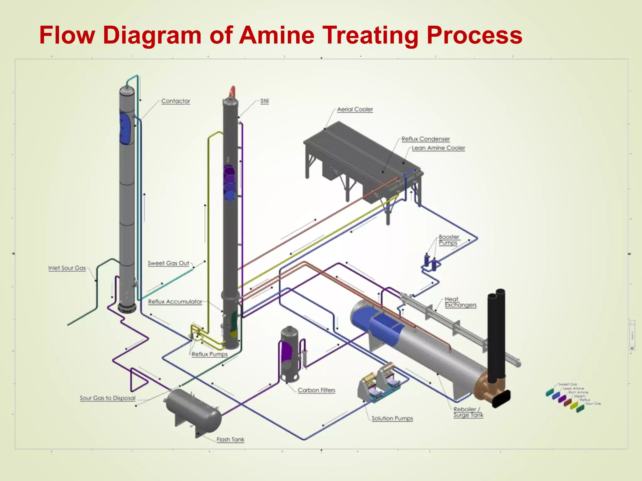

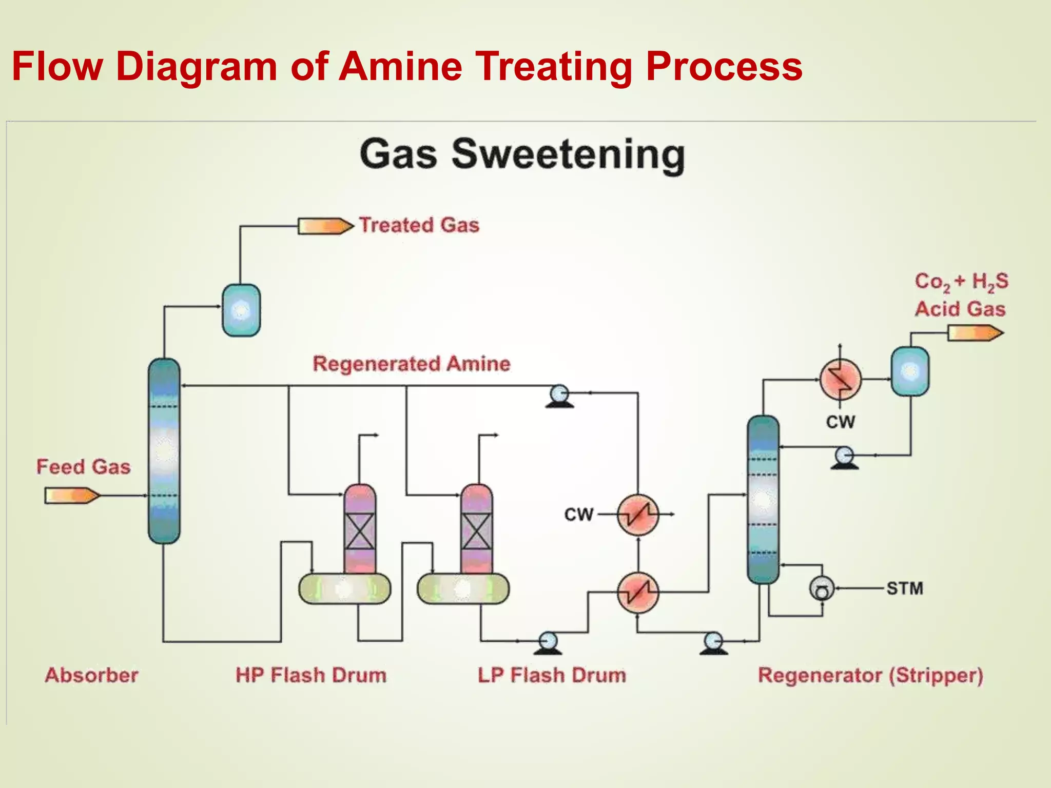


The document discusses liquefied petroleum gas (LPG) and the process of gas sweetening to remove hydrogen sulfide (H2S) and carbon dioxide (CO2) from natural gas. It provides details on a typical amine sweetening process, which involves using an amine solution to absorb the acid gases in an absorber column, then stripping the gases out of the solution in a regenerator using heat. Key steps include absorption in the contactor, stripping in the stripper, condensing the acid gases, and regenerating the lean amine for reuse. Mercury is also typically removed through adsorption on activated carbon beds to prevent equipment corrosion.


![Vibe Coding vs. Spec-Driven Development [Free Meetup]](https://cdn.slidesharecdn.com/ss_thumbnails/vibecodingvsspecdrivendevelopment-251209105622-43f455e7-thumbnail.jpg?width=640&height=640&fit=bounds)


