Download as PDF, PPTX

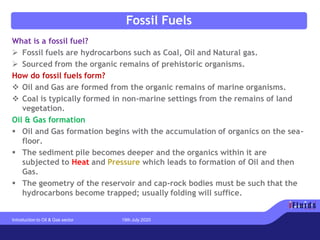
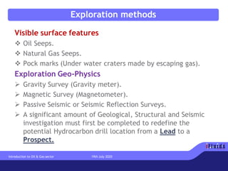
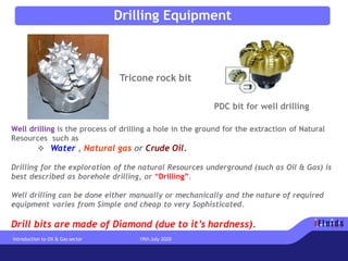


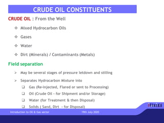
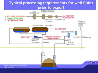
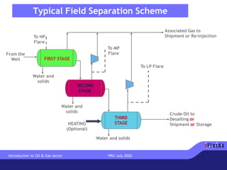


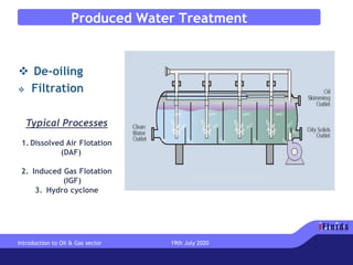


The document provides an overview of oil and gas exploration and processing, including the formation and extraction of fossil fuels, exploration methods, and the drilling process. It discusses the economics of oil exploration, categories of oil reserves, and the technological advancements in offshore drilling. Additionally, it outlines the steps involved in oil and gas production, processing techniques, and the types of offshore facilities used in the industry.


![OVERVIEW OF THE OIL & GAS EXPLORATION AND [Autosaved]](https://cdn.slidesharecdn.com/ss_thumbnails/f980b2ed-b37b-4c91-b049-14cec3820fe3-150826222206-lva1-app6891-thumbnail.jpg?width=640&height=640&fit=bounds)


