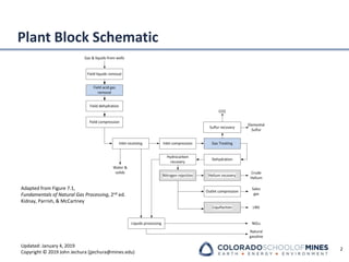
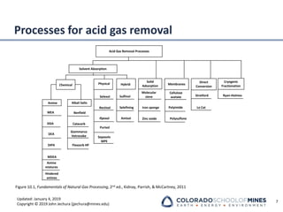
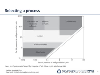
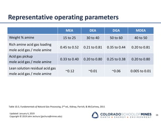
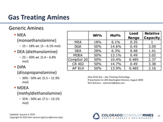
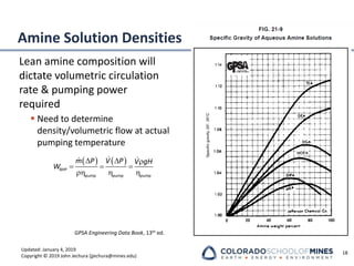
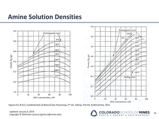
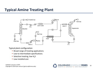
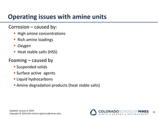
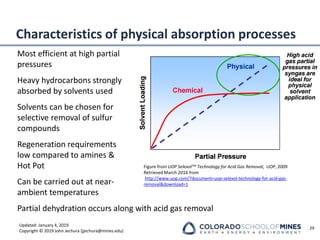
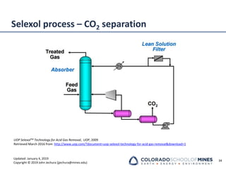
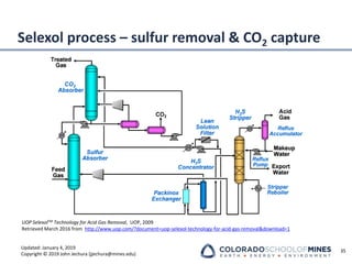
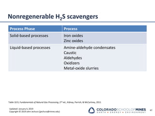
This document provides an overview of acid gas treating processes using amine solvents. It discusses the chemistry of amine solvents and how they selectively remove hydrogen sulfide and carbon dioxide from natural gas. Common amine solvents like MEA, DEA, DGA, and MDEA are examined in terms of their acid gas removal capabilities and operating parameters. The document also reviews the typical configuration of amine treating plants and considerations for designing amine absorption towers and systems. The goal of acid gas treating is to purify natural gas by removing hydrogen sulfide and carbon dioxide to levels that meet pipeline specifications using amine solvent absorption and regeneration processes.


![Updated: January 4, 2019
Copyright © 2019 John Jechura (jjechura@mines.edu)
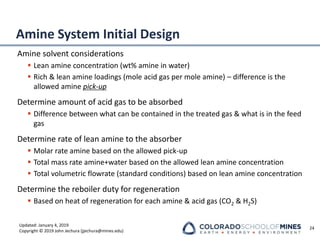
Amine Tower Parameters
Absorber design considerations
▪ Pinch points limit
• Top of tower lean pinch
• Temperature bulge maximum
• Bottom of tower rich pinch
• Confidence level in VLE
▪ Temperature profile indicator
22
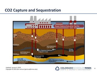
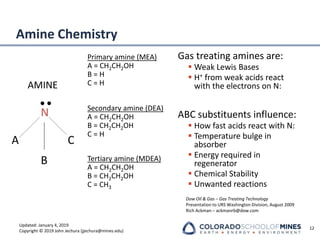
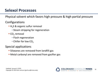
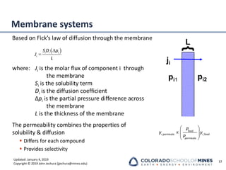
Absorber Temperature Profiles
Liquid Phase
1
2
3
4
5
6
7
8
9
10
11
12
13
14
15
16
17
18
19
20
21
22
23
24
80 100 120 140 160 180 200
Temperature [°F]
Stage
C-1 Conservative
C-2 Controlled Efficient
C-3 Intercooler](https://image.slidesharecdn.com/00presentationimportantgastreating-240115183342-82144402/85/00_Presentation_important_GasTreating-pdf-22-320.jpg)


![[Chemical and process engineering] pdu scale experimental results of co2 remo...](https://cdn.slidesharecdn.com/ss_thumbnails/chemicalandprocessengineeringpdu-scaleexperimentalresultsofco2removalwithamppzsolvent-180705065926-thumbnail.jpg?width=640&height=640&fit=bounds)


