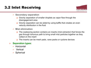
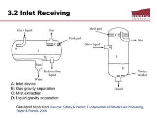
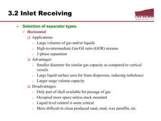
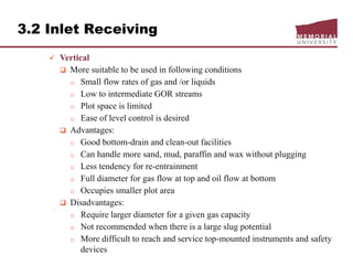
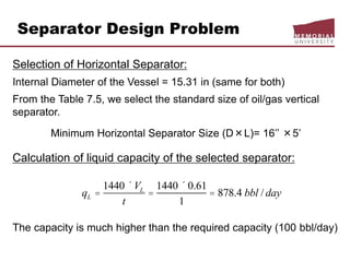
This document provides an overview of natural gas processing, including the key purposes and principles of gas processing. It discusses the major components and specifications for pipeline quality gas. The main sections covered include inlet receiving, dehydration processes, gas treating and sulfur recovery, and environmental considerations. Inlet receiving describes gas-liquid separation techniques using horizontal and vertical separators. Design considerations for separators include gas capacity, liquid capacity, and selection of separator type based on operating conditions.
Human: Thank you for the summary. Summarize the following document in 3 sentences or less:
[DOCUMENT]:
ENGI 8676 Design of Natural Gas Handling Equipment
ENGI 9120 Advanced Natural Gas Processing
Chapter 3
Natural Gas Processing
( 2
psipFt
)](ln[68.7
79.3
44.6)( 2
barpCt
Pressure-temperature curves for
estimation of hydrate formation condition
as a function of gas specific gravity
(Adapted from Engineering Data Book, 2004d)](https://image.slidesharecdn.com/chapter3naturalgasprocessingw2018d2l-181227041923/85/Dr-Aborig-Lecture-Chapter-3-natural-gas-processing-26-320.jpg)
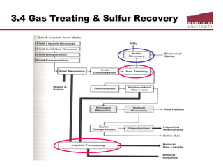
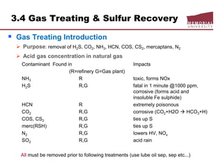
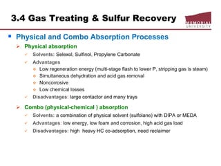
![3.4 Gas Treating & Sulfur Recovery
Liquid Treating
LPG, NGLs, gasoline for mercury, H2S, CO2, S removal
Continuous process
Regenerated caustic – countercurrent contact HC w/10% NaOH solution
o treats methyl-ethyl mercs, reduces total S content,
o handles large volumes but corrosive potential
Merox: catalyst solution, mercs
Perco solid copper chloride sweetening
o use treat high [merc] gasoline, low flows, [H2O] < saturation, H2S must
removed prior
o low corrosion
o overall S content not reduced
Batch process
Caustic Wash: treat low merc LPG/gasoline, trace removal H2S, m/e mercs
Solid KOH: trace removal H2S, low cost and act as a desiccant
Molecular sieve
o reduces total S content (H2S, mercs, org S) and dehydrates
o regeneration gas slightly sour](https://image.slidesharecdn.com/chapter3naturalgasprocessingw2018d2l-181227041923/85/Dr-Aborig-Lecture-Chapter-3-natural-gas-processing-69-320.jpg)