Downloaded 414 times
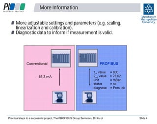


The document outlines practical steps for implementing successful PROFIBUS projects, covering essential aspects like design, installation, and troubleshooting. It emphasizes the importance of training for personnel involved in PROFIBUS systems and details the various types of PROFIBUS communication technologies and applications. Key considerations include diagnostic capabilities, grounding and interference issues, and adherence to installation standards for optimal performance.


![Energy savings using ac drives [autosaved]](https://cdn.slidesharecdn.com/ss_thumbnails/energysavingsusingacdrivesautosaved-130612080722-phpapp02-thumbnail.jpg?width=640&height=640&fit=bounds)


