Downloaded 158 times


![28 Operator Panels BOP-2 and IOP: Working with BOP-2
Example for index parameters
• Pressing OK takes you to [00]
• UP takes you to [01], DOWN back to [00]
• Decide for an index number of your choice
• Press OK again to edit the index
• The value starts flashing
• Adjust the value by pressing UP and DOWN
• Confirm by pressing OK
Some parameters store more than one value. In this case, pressing OK does not take you directly to the
value, but to an index that is displayed in brackets [00] above the actual value.
Example
OKOKOK
A complete list of all parameters
can be found in the “Parameter
Manual: Control Units –
CU240E/B-2” as a download at:
http://support.automation.
siemens.com/WW/view/
en/49946755
If you want to adjust any blink-
ing/active value digit by digit
(using the UP and DOWN button
might just take too long), you
can always press the OK button
longer than two seconds. After
releasing the button, you can
change any single digit by using
the buttons OK (move to next
digit), ESC (move to previous
digit), UP (increase value), and
DOWN (decrease value).
Note
I_DT_G120_Booklet_RZ.indd 28 04.04.2012 13:12:13](https://image.slidesharecdn.com/sinamicsg120treinamentoen-160513070349/75/Sinamics-g120-treinamento-en-28-2048.jpg)


![37
1 2 3
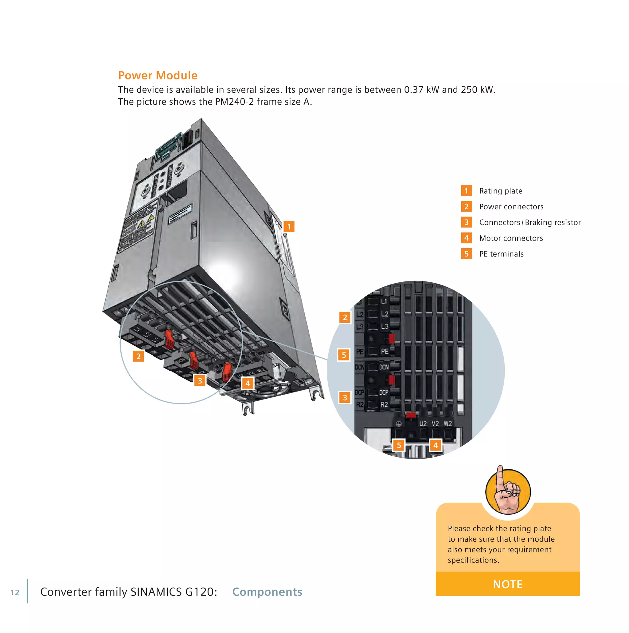
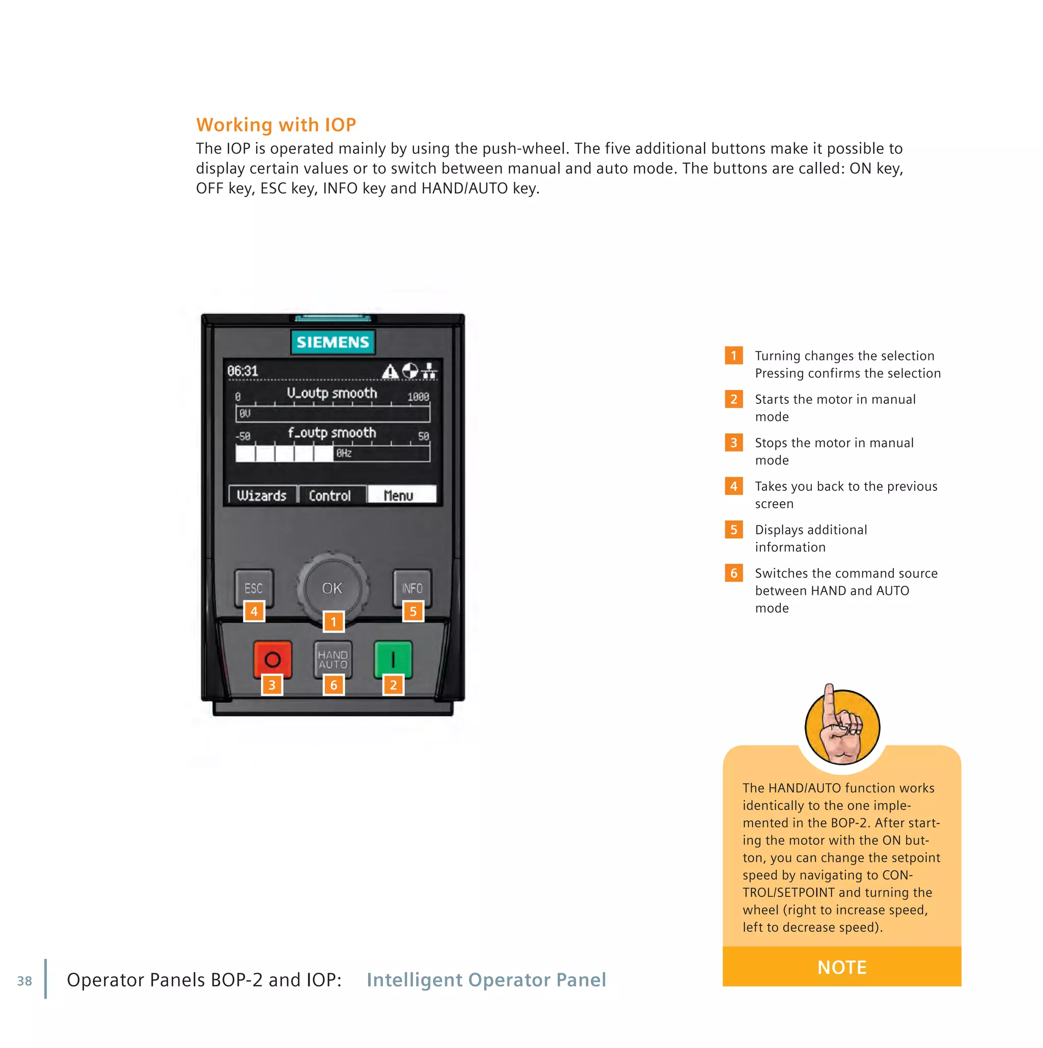
The device
The IOP is a menu-driven device. Its functionality is structured by three options:
1
2
3
The display
All necessary information is user-friendly displayed in plain text or icons. The displayed icons are
shown at the top right-hand edge of the display. They indicate various states of the converter.
• Command source auto / hand
• Inverter status ready / running
• Fault
• Alarm pending
• Battery condition Fully Charged / Discharged
[Wizards] Assists you to set up standard
applications
[Control] Allows you to change setpoint
value, turning direction activates the
jog function in real-time
[Menu] Gives you access to all possible
functionalities
I_DT_G120_Booklet_RZ.indd 37 04.04.2012 13:12:18](https://image.slidesharecdn.com/sinamicsg120treinamentoen-160513070349/75/Sinamics-g120-treinamento-en-37-2048.jpg)


This document provides instructions for installing and wiring the components of a Siemens Sinamics G120 frequency converter, including: - The Power Module supplies voltage to the motor. It comes in various frame sizes and power ranges. - The Control Unit controls and monitors the Power Module. Different Control Unit versions are available with varying terminal assignments and fieldbus interfaces. - The Basic Operator Panel 2 (BOP-2) and Intelligent Operator Panel (IOP) are used for operation and monitoring. The IOP adds graphical displays and application wizards. - Proper mounting, wiring and safety procedures are outlined for installing the Power Module, Control Unit and Operator Panels. Component matching and motor


![Energy savings using ac drives [autosaved]](https://cdn.slidesharecdn.com/ss_thumbnails/energysavingsusingacdrivesautosaved-130612080722-phpapp02-thumbnail.jpg?width=640&height=640&fit=bounds)


