Download as PDF, PPTX
![17
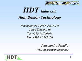
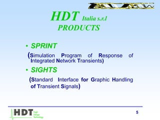
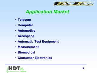
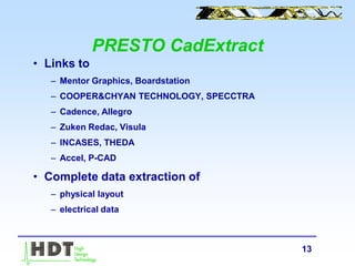
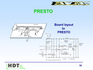
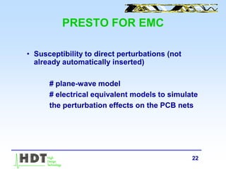
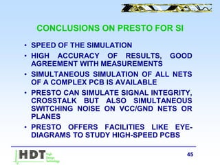
PRESTO Results70.00 80.00 100.00 120.00 140.00 160.00 180.00
TIME[nS]
-4.00V
-2.00V
0.00V
2.00V
4.00V
6.00V
8.00V
#U4_1
#IC23_4
lower and upper masks
maskviolations
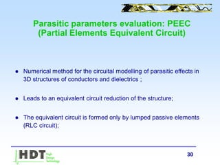
Net CLK1 upper and lower masks v iolation Error f igure: 8.12
Net DAT1 upper and lower masks v iolation Error f igure: 6.01
Net ADD1 lower mask v iolation Error f igure: 0.21
Net ADD2 upper mask v iolation Error f igure: 0.11
Net ADD3 upper mask v iolation Error f igure: 0.11
Net RD no v iolation Error f igure: -
Net RDN no v iolation Error f igure: -
70.00 80.00 100.00 120.00 140.00 160.00 180.00
TIME[nS]
-4V
-2V
0V
2V
4V
6V
8V
Eye-diagramopening
Jitter](https://image.slidesharecdn.com/prestosi-170317144158/85/HDT-TOOLS-PRESENTATION-2000-17-320.jpg)
![40
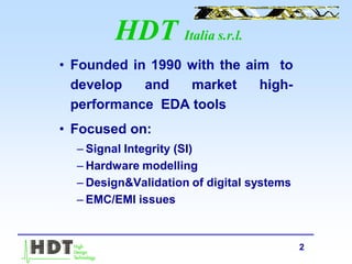
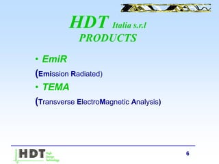
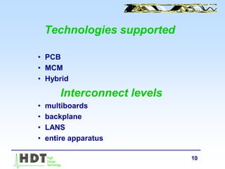
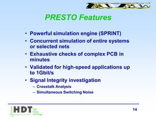
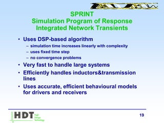
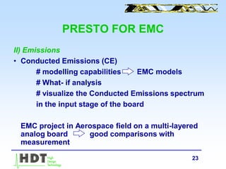
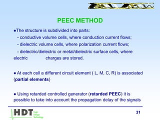
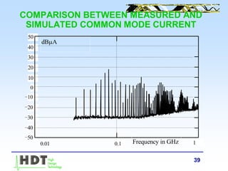
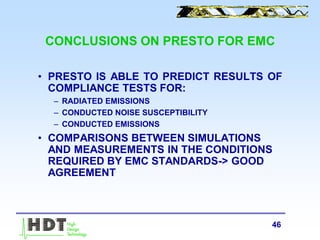
COMMON MODE CURRENT THROUGH THE
CABLE (EmiR_Cable)
0.01 0.10 1.00
-50.00
-40.00
-30.00
-20.00
-10.00
0.00
10.00
20.00
30.00
40.00
50.00
f [GHz]
dBA](https://image.slidesharecdn.com/prestosi-170317144158/85/HDT-TOOLS-PRESENTATION-2000-40-320.jpg)
![41
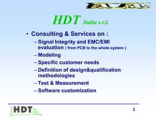
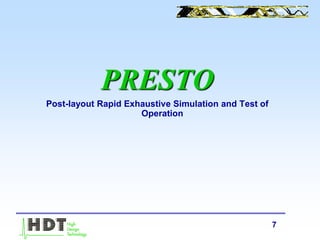
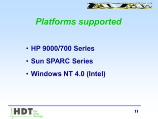
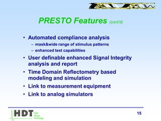
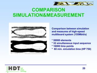
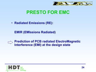
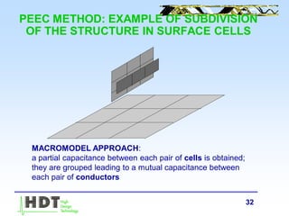
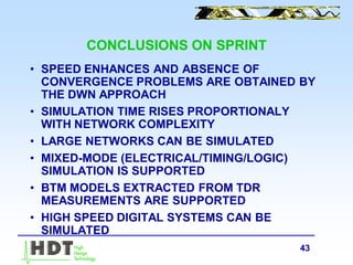
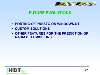
COMPARISON BETWEEN THE
MEASURED AND THE SIMULATED
RADIATED FIELD
10 100 1 10
320
10
0
10
20
30
40
50
60
70
80
Frequency in MHz
|E| [dBV/m]](https://image.slidesharecdn.com/prestosi-170317144158/85/HDT-TOOLS-PRESENTATION-2000-41-320.jpg)
![42
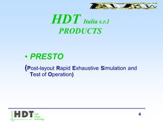
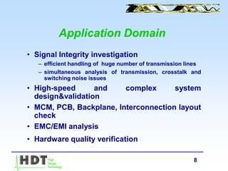
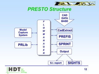
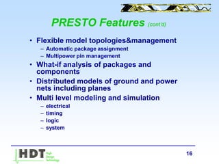
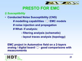
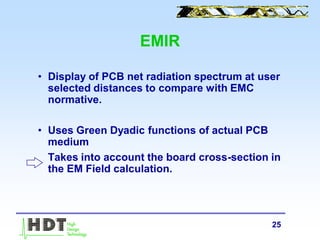
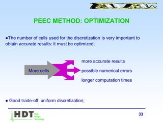
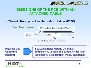
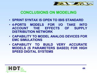
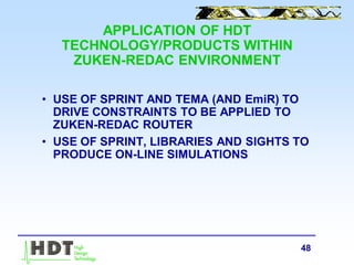
EMISSIONS OF THE PCB WITH AN
ATTACHED CABLE (EmiR_CABLE)|E| [dBV/m]
Frequency in GHz
0.00 0.01 0.10
-20
-10
0
10
20
30
40
50
60
70
80
1.0](https://image.slidesharecdn.com/prestosi-170317144158/85/HDT-TOOLS-PRESENTATION-2000-42-320.jpg)

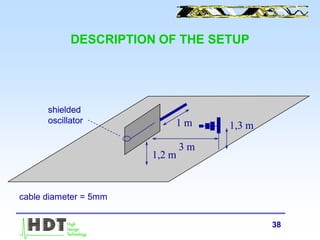
HDT Italia produces EDA tools for signal integrity, hardware modeling, and EMC/EMI analysis and validation. Their main product is PRESTO, which uses the SPRINT simulation engine to enable fast, exhaustive simulation of entire printed circuit boards. PRESTO can analyze signal integrity issues, EMC/EMI compliance, and validate design functionality. It produces detailed reports and can interface with measurement equipment for validation. HDT also provides consulting services and the EmiR tool for predicting radiated emissions from PCB designs.


![[IJET-V1I3P5] Authors :Dushyant Kumar Soni, Ashish Hiradhar](https://cdn.slidesharecdn.com/ss_thumbnails/ijet-v1i3p5-150519153226-lva1-app6891-thumbnail.jpg?width=640&height=640&fit=bounds)


