Download as PDF, PPTX
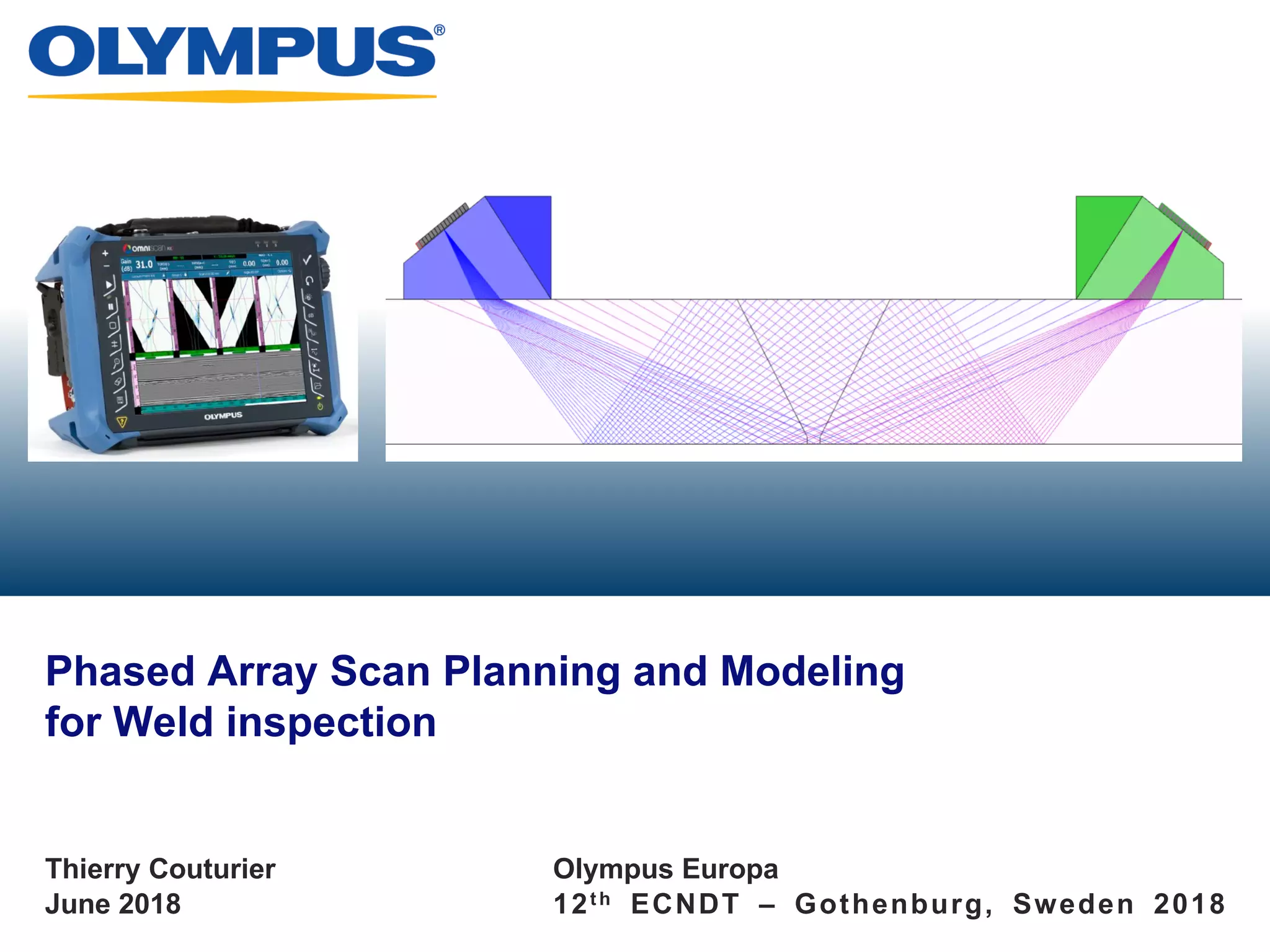
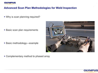
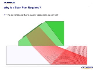
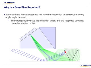
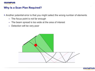
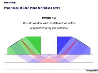
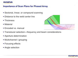
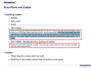
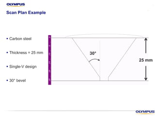

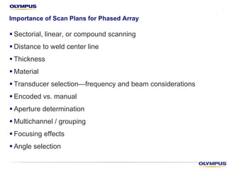
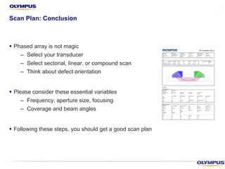

The document discusses the importance of scan planning for weld inspection using phased array technology, outlining key methodologies and definitions. It emphasizes the need for a documented inspection strategy to ensure repeatability and reduce potential errors in detection due to incorrect angles or insufficient coverage. Additionally, it covers factors influencing the scan plan, such as transducer selection, scan types, and the integration of phased array and time-of-flight diffraction techniques.