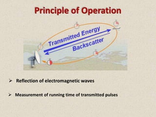
What is RADAR ?
 RADAR is an acronym for RAdio Detection And Ranging.


 RADAR is an object detection system that uses electromagnetic waves
  to identify the range,altitude,direction or speed of both moving and
  fixed objects such as aircrafts,ships,motor vehicles,weather
  formations and terrain.
Principle of Operation


 Reflection of electromagnetic waves

 Measurement of running time of transmitted pulses
Radar Basic Principles


   Transmitter
   Duplexer
   Receiver
   Radar Antenna
   Indicator
Principle of Measurement

 Distance Determination.

 Direction Determination.

 Elevation Angle.

 Range Resolution.
Distance Determination


 The distance is determined from the running time of the high frequency transmitted
  signal and the propagation c0. The actual range of a target from the radar is known
  as slant range. Slant range is the line of sight distance between the radar and the
  object illuminated. Since the waves travel to a target and back, the round trip time is
  dividing by two in order to obtain the time the wave took to reach the target.
  Therefore the following formula arises for the slant range:
   R = c0· t/2               where: c0 = speed of light = 3·108 m/s
                                       t = measured running time [s]
                                      R = slant range antenna - aim [m]
  The distances are expressed in kilometers or nautical miles
  (1 NM =1.852 km).
Direction Determination

 The angular determination of the target is determined by the directivity of the
  antenna. Directivity, sometimes known as the directive gain, is the ability of the
  antenna to concentrate the transmitted energy in a particular direction. By
  measuring the direction in which the antenna is pointing when the echo is received,
  both the azimuth and elevation angles from the radar to the object or target can be
  determined.
Direction Determination


 The antennas of most radar systems are designed to radiate energy in a one-
  directional lobe or beam that can be moved in bearing simply by moving the
  antenna. The point of maximum echo, determined by the detection circuitry or
  visually by the operator, is when the beam points direct at the target. Weapons-
  control and guidance radar systems are positioned to the point of maximum
  signal return and maintained at that position either manually or by automatic
  tracking circuits.
Elevation Angle


 Altitude or height-finding search radars use a very narrow beam in
  the vertical plane. The beam is mechanically or electronically
  scanned in elevation to pinpoint targets.
 The elevation angle is the angle between the horizontal plane and
  the line of sight, measured in the vertical plane. The Greek letter
  Epsilon (ε) describes the elevation angle. The elevation angle is
  positive above the horizon (0° elevation angle), but negative below
  the horizon.
Range Resolution

 Range resolution is the ability of a radar system to distinguish between two or more
  targets on the same bearing but at different ranges. The degree of range resolution
  depends on the width of the transmitted pulse, the types and sizes of targets, and the
  efficiency of the receiver and indicator. Pulse width is the primary factor in range
  resolution. A well-designed radar system, with all other factors at maximum efficiency,
  should be able to distinguish targets separated by one-half the pulse width time τ.
  Therefore, the theoretical range resolution cell of a radar system can be calculated from
  the following equation:
         Sr ≥ c 0 · τ / 2    where: c0 = speed of light = 3·108 m/s
                                       τ = pulse width time
Range Resolution
Radar Timing

 Pulse Repetition Frequency.

 Duty Cycle.

 Dwell Time.
Pulse Repetition Frequency


 The Pulse Repetition Frequency (PRF) of the radar system is the number of pulses
  that are transmitted per second.


 Radar systems radiate each pulse at the carrier frequency during transmit time
  (or Pulse Width PW), wait for returning echoes during listening or rest time, and
  then radiate the next pulse..The time between the beginning of one pulse and the
  start of the next pulse is called pulse-repetition time (prt) and is equal to the
  reciprocal of prf as follows:
                                     PRT = 1/PRF
Duty Cycle


 The product of pulse width (pw) and pulse-repetition frequency (prf)
  is called the duty cycle of a radar system.

 Duty cycle is the fraction of time that a system is in an “active” state.
  In particular, it is used in the following contexts: Duty cycle is the
  proportion of time during which a component, device, or system is
  operated.
Dwell Time
 The time that an antenna beam spends on a target is called dwell time TD.
  The dwell time of a 2D–search radar depends predominantly on:
   1) the antennas horizontally beam width ΘAZ and
   2) the turn speed n of the antenna (rotations per minute).
  The dwell time can be calculated using the following equation:

       TD = (ΘAZ · 60)/(360° · n)         ; in [seconds]
Radar Equation
 The power Pr returning to the receiving antenna is given by the
  radar equation:


    where
    Pt = transmitter power
    Gt = gain of the transmitting antenna
    Ar = effective aperture (area) of the receiving antenna
    σ = radar cross section, or scattering coefficient of the target
    F = pattern propagation factor
    Rt = distance from the transmitter to the target
    Rr = distance from the target to the receiver.
Radar Cross Section
 The size and ability of a target to reflect radar energy can be summarized into a single
  term, σ, known as the radar cross-section, which has units of m². If absolutely all of
  the incident radar energy on the target were reflected equally in all directions, then
  the radar cross section would be equal to the target's cross-sectional area as seen by
  the transmitter. In practice, some energy is absorbed and the reflected energy is not
  distributed equally in all directions. Therefore, the radar cross-section is quite difficult
  to estimate and is normally determined by measurement.

 The target radar cross sectional area depends on:
    1) The airplane’s physical geometry and exterior features,
    2) The direction of the illuminating radar,
    3) The radar transmitters frequency,
    4) The used material types.
Interference

 Noise.

 Clutter.

 Jamming.
Noise
 Signal noise is an internal source of random variations in the signal, which is
  generated by all electronic components. Noise typically appears as random variations
  superimposed on the desired echo signal received in the radar receiver. The lower the
  power of the desired signal, the more difficult it is to discern it from the noise
  (similar to trying to hear a whisper while standing near a busy road).

 Noise figure is a measure of the noise produced by a receiver compared to an ideal
  receiver, and this needs to be minimized.

 Noise is also generated by external sources, most importantly the natural thermal
  radiation of the background scene surrounding the target of interest.

 There will be also flicker noise due to electrons transit, but depending on 1/f, will
  be much lower than thermal noise when the frequency is high.
Clutter


 Clutter refers to radio frequency (RF) echoes returned from targets which are
  uninteresting to the radar operators. Such targets include natural objects such as
  ground, sea, precipitation (such as rain, snow or hail), sand storms, animals
  (especially birds), atmospheric turbulence, and other atmospheric effects, such as
  ionosphere reflections, meteor trails, and three body scatter spike. Clutter may also
  be returned from man-made objects such as buildings and, intentionally, by radar
  countermeasures such as chaff.

 Clutter may also originate from multipath echoes from valid targets due to ground
  reflection, atmospheric ducting or ionospheric reflection/refraction.
Clutter
 The basic types of clutter can be summarized as follows:

      1) Surface Clutter – Ground or sea returns are typical surface clutter. Returns from
         geographical land masses are generally stationary, however, the effect of wind
         on trees etc means that the target can introduce a Doppler Shift to the radar
         return. This Doppler shift is an important method of removing unwanted
         signals in the signal processing part of a radar system. Clutter returned from the
         sea generally also has movement associated with the waves.


     2) Volume Clutter – Weather or chaff are typical volume clutter. In the air, the most
        significant problem is weather clutter. This can be produced from rain or snow
        and can have a significant Doppler content.
Clutter
3) Point Clutter – Birds, windmills and individual tall buildings are typical point
   clutter and are not extended in nature. Moving point clutter is sometimes
   described as angels. Birds and insects produce clutter, which can be very
   difficult to remove because the characteristics are very much like aircraft.
Doppler Effect
 In radar technology the Doppler Effect is using for two tasks:
       1) Speed measuring and
       2) MTI - Moving Target Indication
Doppler Effect
Jamming
 Radar jamming refers to radio frequency signals originating from
  sources outside the radar, transmitting in the radar's frequency and
  thereby masking targets of interest. Jamming may be intentional, as
  with an electronic warfare (EW) tactic, or unintentional, as with
  friendly forces operating equipment that transmits using the same
  frequency range. Jamming is considered an active interference
  source, since it is initiated by elements outside the radar and in
  general unrelated to the radar signals.
Radar Frequency Bands
Air Defense Radars
 The maximum range of Air-Defense Radar can exceed 300 miles, and
  the bearing coverage is a complete 360-degree circle.

 Another function of the Air-Defense Radar is guiding combat air
  patrol (CAP) aircraft to a position suitable to intercept an enemy
  aircraft.

 Major Air-Defense Radar Applications are:
   1) Long-range early warning (including airborne early warning, AEW)
   2) Ballistic missile warning and acquisition
   3) Height-finding
   4) Ground-controlled interception (GCI)
Air Traffic Control Radar
 The following Air Traffic Control (ATC) surveillance, approach and
  landing radars are commonly used in Air Traffic Management (ATM):
     1) En-route radar systems,
     2) Air Surveillance Radar (ASR) systems,
     3) Precision Approach Radar (PAR) systems,
     4) surface movement radars and
     5) special weather radars.
En-Route Radars
 En-route radar systems operate in L-Band usually. These radar sets
  initially detect and determine the position, course, and speed of air
  targets in a relatively large area up to 250 nm.
Air Surveillance Radar
 Airport Surveillance Radar (ASR) is an approach control radar used to
  detect and display an aircraft's position in the terminal area. These
  radar sets operate usually in E-Band, and are capable of reliably
  detecting and tracking aircraft at altitudes below 25,000 feet (7,620 m)
  and within 40 to 60 nautical miles (75 to 110 km) of their airport.
Precision Approach Radar
 The ground-controlled approach is a control mode in which an aircraft
  is able to land in bad weather. The pilot is guided by ground control
  using precision approach radar. The guidance information is obtained
  by the radar operator and passed to the aircraft by either voice radio
  or a computer link to the aircraft.
Surface Movement Radar
 The Surface Movement Radar (SMR) scans the airport surface to locate
  the positions of aircraft and ground vehicles and displays them for air
  traffic controllers in bad weather. Surface movement radars operate in
  J- to X- Band and use an extremely short pulse-width to provide an
  acceptable range-resolution.
Special Weather Radar
 Weather radar is very important for the air traffic management.
  There are weather-radars specially designed for the air traffic safety.
Phased array Antenna
Advantages                                     Disadvantages
•high gain width los side lobes                •the coverage is limited to a 120 degree
•Ability to permit the beam to jump from       sector in azimuth and elevation
one target to the next in a few microseconds   •deformation of the beam while the
•Ability to provide an agile beam under        deflection
computer control                               •low frequency agility
•arbitrarily modes of surveillance and         •very complex structure (processor, phase
tracking                                       shifters)
•free eligible Dwell Time                      •still high costs
•multifunction operation by emitting several
beams simultaneously
•Fault of single components reduces the
capability and beam sharpness, but the
system remains operational
Phased array Antenna
Types of Scan
 Primary Scan: A scanning technique where the main antenna
  aerial is moved to produce a scanning beam, examples include
  circular scan, sector scan etc

 Secondary Scan: A scanning technique where the antenna feed
  is moved to produce a scanning beam, examples include conical
  scan, unidirectional sector scan, lobe switching etc.

 Palmer Scan: A scanning technique that produces a scanning beam
  by moving the main antenna and its feed. A Palmer Scan is a
  combination of a Primary Scan and a Secondary Scan.
PPI Scope
Stealth Technology

 Material.

 Shape, Directivity and Orientation.

 Active Cancellation.

 Radar Absorbent Paint.
Material
 Materials such as metal are strongly radar reflective and tend to produce
  strong signals. Wood and cloth (such as portions of planes and balloons used
  to be commonly made) or plastic and fibreglass are less reflective or indeed
  transparent to RADAR making them suitable for radomes. Even a very thin
  layer of metal can make an object strongly radar reflective.


 Submarines have extensive usage of rubber mountings to isolate and avoid
  mechanical noises that could reveal locations to underwater passive sonar
  arrays.
Shape, Directivity and Orientation
 The surfaces of the F-117A are designed to be flat and very angled. This has
  the effect that RADAR will be incident at a large angle (to the normal ray) that
  will then bounce off at a similarly high reflected angle; it is forward-scattered.
  The edges are sharp to prevent there being rounded surfaces. Rounded
   surfaces will often have some portion of the surface normal to the RADAR
   source. As any ray incident along the normal will reflect back along the
   normal this will make for a strong reflected signal.

 With purpose shaping, the shape of the target’s reflecting surfaces is designed
  such that they reflect energy away from the source.
F-117A
VISBY CLASS CORVETTE
Active Cancellation
 With active cancellation, the target generates a radar signal equal in intensity
  but opposite in phase to the predicted reflection of an incident radar signal .
  This creates destructive interference between the reflected and generated
  signals,resulting in reduced RCS.
Radar Absorbent Paint
 The SR-71 Blackbird and other planes were painted with a special "iron ball
  paint“. This consisted of small metallic-coated balls. RADAR energy is
  converted to heat rather than being reflected.


 One of the most commonly known types of RAM is iron ball paint. It contains
  tiny spheres coated with carbonyl iron or ferrite. Radar waves induce
  molecular oscillations from the alternating magnetic field in this paint, which
  leads to conversion of the radar energy into heat. The heat is then transferred
  to the aircraft and dissipated.
SR-71 Blackbird
THANK YOU
References:
   http://en.wikipedia.org/wiki/Radar


   http://www.radartutorial.eu/01.basics/rb01.en.html

Radar

  • 2.
    What is RADAR?  RADAR is an acronym for RAdio Detection And Ranging.  RADAR is an object detection system that uses electromagnetic waves to identify the range,altitude,direction or speed of both moving and fixed objects such as aircrafts,ships,motor vehicles,weather formations and terrain.
  • 3.
    Principle of Operation Reflection of electromagnetic waves  Measurement of running time of transmitted pulses
  • 4.
    Radar Basic Principles  Transmitter  Duplexer  Receiver  Radar Antenna  Indicator
  • 5.
    Principle of Measurement Distance Determination.  Direction Determination.  Elevation Angle.  Range Resolution.
  • 6.
    Distance Determination  Thedistance is determined from the running time of the high frequency transmitted signal and the propagation c0. The actual range of a target from the radar is known as slant range. Slant range is the line of sight distance between the radar and the object illuminated. Since the waves travel to a target and back, the round trip time is dividing by two in order to obtain the time the wave took to reach the target. Therefore the following formula arises for the slant range: R = c0· t/2 where: c0 = speed of light = 3·108 m/s t = measured running time [s] R = slant range antenna - aim [m] The distances are expressed in kilometers or nautical miles (1 NM =1.852 km).
  • 7.
    Direction Determination  Theangular determination of the target is determined by the directivity of the antenna. Directivity, sometimes known as the directive gain, is the ability of the antenna to concentrate the transmitted energy in a particular direction. By measuring the direction in which the antenna is pointing when the echo is received, both the azimuth and elevation angles from the radar to the object or target can be determined.
  • 8.
    Direction Determination  Theantennas of most radar systems are designed to radiate energy in a one- directional lobe or beam that can be moved in bearing simply by moving the antenna. The point of maximum echo, determined by the detection circuitry or visually by the operator, is when the beam points direct at the target. Weapons- control and guidance radar systems are positioned to the point of maximum signal return and maintained at that position either manually or by automatic tracking circuits.
  • 9.
    Elevation Angle  Altitudeor height-finding search radars use a very narrow beam in the vertical plane. The beam is mechanically or electronically scanned in elevation to pinpoint targets.  The elevation angle is the angle between the horizontal plane and the line of sight, measured in the vertical plane. The Greek letter Epsilon (ε) describes the elevation angle. The elevation angle is positive above the horizon (0° elevation angle), but negative below the horizon.
  • 10.
    Range Resolution  Rangeresolution is the ability of a radar system to distinguish between two or more targets on the same bearing but at different ranges. The degree of range resolution depends on the width of the transmitted pulse, the types and sizes of targets, and the efficiency of the receiver and indicator. Pulse width is the primary factor in range resolution. A well-designed radar system, with all other factors at maximum efficiency, should be able to distinguish targets separated by one-half the pulse width time τ. Therefore, the theoretical range resolution cell of a radar system can be calculated from the following equation: Sr ≥ c 0 · τ / 2 where: c0 = speed of light = 3·108 m/s τ = pulse width time
  • 11.
  • 12.
    Radar Timing  PulseRepetition Frequency.  Duty Cycle.  Dwell Time.
  • 13.
    Pulse Repetition Frequency The Pulse Repetition Frequency (PRF) of the radar system is the number of pulses that are transmitted per second.  Radar systems radiate each pulse at the carrier frequency during transmit time (or Pulse Width PW), wait for returning echoes during listening or rest time, and then radiate the next pulse..The time between the beginning of one pulse and the start of the next pulse is called pulse-repetition time (prt) and is equal to the reciprocal of prf as follows: PRT = 1/PRF
  • 14.
    Duty Cycle  Theproduct of pulse width (pw) and pulse-repetition frequency (prf) is called the duty cycle of a radar system.  Duty cycle is the fraction of time that a system is in an “active” state. In particular, it is used in the following contexts: Duty cycle is the proportion of time during which a component, device, or system is operated.
  • 15.
    Dwell Time  Thetime that an antenna beam spends on a target is called dwell time TD. The dwell time of a 2D–search radar depends predominantly on: 1) the antennas horizontally beam width ΘAZ and 2) the turn speed n of the antenna (rotations per minute). The dwell time can be calculated using the following equation: TD = (ΘAZ · 60)/(360° · n) ; in [seconds]
  • 16.
    Radar Equation  Thepower Pr returning to the receiving antenna is given by the radar equation: where Pt = transmitter power Gt = gain of the transmitting antenna Ar = effective aperture (area) of the receiving antenna σ = radar cross section, or scattering coefficient of the target F = pattern propagation factor Rt = distance from the transmitter to the target Rr = distance from the target to the receiver.
  • 17.
    Radar Cross Section The size and ability of a target to reflect radar energy can be summarized into a single term, σ, known as the radar cross-section, which has units of m². If absolutely all of the incident radar energy on the target were reflected equally in all directions, then the radar cross section would be equal to the target's cross-sectional area as seen by the transmitter. In practice, some energy is absorbed and the reflected energy is not distributed equally in all directions. Therefore, the radar cross-section is quite difficult to estimate and is normally determined by measurement.  The target radar cross sectional area depends on: 1) The airplane’s physical geometry and exterior features, 2) The direction of the illuminating radar, 3) The radar transmitters frequency, 4) The used material types.
  • 18.
  • 19.
    Noise  Signal noiseis an internal source of random variations in the signal, which is generated by all electronic components. Noise typically appears as random variations superimposed on the desired echo signal received in the radar receiver. The lower the power of the desired signal, the more difficult it is to discern it from the noise (similar to trying to hear a whisper while standing near a busy road).  Noise figure is a measure of the noise produced by a receiver compared to an ideal receiver, and this needs to be minimized.  Noise is also generated by external sources, most importantly the natural thermal radiation of the background scene surrounding the target of interest.  There will be also flicker noise due to electrons transit, but depending on 1/f, will be much lower than thermal noise when the frequency is high.
  • 20.
    Clutter  Clutter refersto radio frequency (RF) echoes returned from targets which are uninteresting to the radar operators. Such targets include natural objects such as ground, sea, precipitation (such as rain, snow or hail), sand storms, animals (especially birds), atmospheric turbulence, and other atmospheric effects, such as ionosphere reflections, meteor trails, and three body scatter spike. Clutter may also be returned from man-made objects such as buildings and, intentionally, by radar countermeasures such as chaff.  Clutter may also originate from multipath echoes from valid targets due to ground reflection, atmospheric ducting or ionospheric reflection/refraction.
  • 21.
    Clutter  The basictypes of clutter can be summarized as follows: 1) Surface Clutter – Ground or sea returns are typical surface clutter. Returns from geographical land masses are generally stationary, however, the effect of wind on trees etc means that the target can introduce a Doppler Shift to the radar return. This Doppler shift is an important method of removing unwanted signals in the signal processing part of a radar system. Clutter returned from the sea generally also has movement associated with the waves. 2) Volume Clutter – Weather or chaff are typical volume clutter. In the air, the most significant problem is weather clutter. This can be produced from rain or snow and can have a significant Doppler content.
  • 22.
    Clutter 3) Point Clutter– Birds, windmills and individual tall buildings are typical point clutter and are not extended in nature. Moving point clutter is sometimes described as angels. Birds and insects produce clutter, which can be very difficult to remove because the characteristics are very much like aircraft.
  • 23.
    Doppler Effect  Inradar technology the Doppler Effect is using for two tasks: 1) Speed measuring and 2) MTI - Moving Target Indication
  • 24.
  • 25.
    Jamming  Radar jammingrefers to radio frequency signals originating from sources outside the radar, transmitting in the radar's frequency and thereby masking targets of interest. Jamming may be intentional, as with an electronic warfare (EW) tactic, or unintentional, as with friendly forces operating equipment that transmits using the same frequency range. Jamming is considered an active interference source, since it is initiated by elements outside the radar and in general unrelated to the radar signals.
  • 26.
  • 27.
    Air Defense Radars The maximum range of Air-Defense Radar can exceed 300 miles, and the bearing coverage is a complete 360-degree circle.  Another function of the Air-Defense Radar is guiding combat air patrol (CAP) aircraft to a position suitable to intercept an enemy aircraft.  Major Air-Defense Radar Applications are: 1) Long-range early warning (including airborne early warning, AEW) 2) Ballistic missile warning and acquisition 3) Height-finding 4) Ground-controlled interception (GCI)
  • 28.
    Air Traffic ControlRadar  The following Air Traffic Control (ATC) surveillance, approach and landing radars are commonly used in Air Traffic Management (ATM): 1) En-route radar systems, 2) Air Surveillance Radar (ASR) systems, 3) Precision Approach Radar (PAR) systems, 4) surface movement radars and 5) special weather radars.
  • 29.
    En-Route Radars  En-routeradar systems operate in L-Band usually. These radar sets initially detect and determine the position, course, and speed of air targets in a relatively large area up to 250 nm.
  • 30.
    Air Surveillance Radar Airport Surveillance Radar (ASR) is an approach control radar used to detect and display an aircraft's position in the terminal area. These radar sets operate usually in E-Band, and are capable of reliably detecting and tracking aircraft at altitudes below 25,000 feet (7,620 m) and within 40 to 60 nautical miles (75 to 110 km) of their airport.
  • 31.
    Precision Approach Radar The ground-controlled approach is a control mode in which an aircraft is able to land in bad weather. The pilot is guided by ground control using precision approach radar. The guidance information is obtained by the radar operator and passed to the aircraft by either voice radio or a computer link to the aircraft.
  • 32.
    Surface Movement Radar The Surface Movement Radar (SMR) scans the airport surface to locate the positions of aircraft and ground vehicles and displays them for air traffic controllers in bad weather. Surface movement radars operate in J- to X- Band and use an extremely short pulse-width to provide an acceptable range-resolution.
  • 33.
    Special Weather Radar Weather radar is very important for the air traffic management. There are weather-radars specially designed for the air traffic safety.
  • 34.
    Phased array Antenna Advantages Disadvantages •high gain width los side lobes •the coverage is limited to a 120 degree •Ability to permit the beam to jump from sector in azimuth and elevation one target to the next in a few microseconds •deformation of the beam while the •Ability to provide an agile beam under deflection computer control •low frequency agility •arbitrarily modes of surveillance and •very complex structure (processor, phase tracking shifters) •free eligible Dwell Time •still high costs •multifunction operation by emitting several beams simultaneously •Fault of single components reduces the capability and beam sharpness, but the system remains operational
  • 35.
  • 36.
    Types of Scan Primary Scan: A scanning technique where the main antenna aerial is moved to produce a scanning beam, examples include circular scan, sector scan etc  Secondary Scan: A scanning technique where the antenna feed is moved to produce a scanning beam, examples include conical scan, unidirectional sector scan, lobe switching etc.  Palmer Scan: A scanning technique that produces a scanning beam by moving the main antenna and its feed. A Palmer Scan is a combination of a Primary Scan and a Secondary Scan.
  • 37.
  • 38.
    Stealth Technology  Material. Shape, Directivity and Orientation.  Active Cancellation.  Radar Absorbent Paint.
  • 39.
    Material  Materials suchas metal are strongly radar reflective and tend to produce strong signals. Wood and cloth (such as portions of planes and balloons used to be commonly made) or plastic and fibreglass are less reflective or indeed transparent to RADAR making them suitable for radomes. Even a very thin layer of metal can make an object strongly radar reflective.  Submarines have extensive usage of rubber mountings to isolate and avoid mechanical noises that could reveal locations to underwater passive sonar arrays.
  • 40.
    Shape, Directivity andOrientation  The surfaces of the F-117A are designed to be flat and very angled. This has the effect that RADAR will be incident at a large angle (to the normal ray) that will then bounce off at a similarly high reflected angle; it is forward-scattered. The edges are sharp to prevent there being rounded surfaces. Rounded surfaces will often have some portion of the surface normal to the RADAR source. As any ray incident along the normal will reflect back along the normal this will make for a strong reflected signal.  With purpose shaping, the shape of the target’s reflecting surfaces is designed such that they reflect energy away from the source.
  • 41.
  • 42.
  • 43.
    Active Cancellation  Withactive cancellation, the target generates a radar signal equal in intensity but opposite in phase to the predicted reflection of an incident radar signal . This creates destructive interference between the reflected and generated signals,resulting in reduced RCS.
  • 44.
    Radar Absorbent Paint The SR-71 Blackbird and other planes were painted with a special "iron ball paint“. This consisted of small metallic-coated balls. RADAR energy is converted to heat rather than being reflected.  One of the most commonly known types of RAM is iron ball paint. It contains tiny spheres coated with carbonyl iron or ferrite. Radar waves induce molecular oscillations from the alternating magnetic field in this paint, which leads to conversion of the radar energy into heat. The heat is then transferred to the aircraft and dissipated.
  • 45.
  • 46.
  • 47.
    References: http://en.wikipedia.org/wiki/Radar  http://www.radartutorial.eu/01.basics/rb01.en.html