2. ١/١٢/١٤٣٦
٢
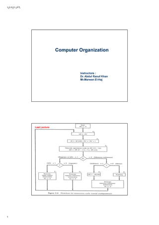
Determine the type of Instruction
The three instruction types are subdivided
into four separate paths
D’7IT3 : AR M[AR]
D’7I’T3 : Nothing
D7I’T3 : Execute register-reference Instruction
D7IT3 : Execute Input-Output instruction
Last Lecture
Register Reference Instructions
The control function and Microoperation for
register reference are listed below. These
instructions are executed with the clock
transition associated with timing Variable T3.
Each control function needs the Boolean
relation D7I’ T3, which we designate by r.
The control function is distinguished by one
of the bits in IR(0-11)
5. ١/١٢/١٤٣٦
٥
Input Output Configuration
Input process
Initially input flag FGI is cleared to 0. When a
key is struck in the keyboard, an 8 bit
character is shifted into INPR and FGI is set
1. As long as the flag is set, the information
in INPR cannot be changed. The computer
checks the flag bit; if it is 1, the information
from INPR is transferred in parallel into AC
and FGI is cleared to 0.
6. ١/١٢/١٤٣٦
٦
Output process
Initially, the FGO = 1. the computer checks the
flag bit; if it is 1, the information from AC is
transferred in parallel to OUTR and FGO is
cleared to 0. the output device accepts the
coded information, prints the character and
when the operation is completed, sets FGO = 1.
Computer does not load new character in
OUTR if FGO = 0.
Input-Output instructions
For all input-output instructions, D7=1, I=1
and T3=1. Each control function needs a
Boolean relation D7IT3 = p (say)

![١/١٢/١٤٣٦
٢
Determine the type of Instruction
The three instruction types are subdivided
into four separate paths
D’7IT3 : AR M[AR]
D’7I’T3 : Nothing
D7I’T3 : Execute register-reference Instruction
D7IT3 : Execute Input-Output instruction
Last Lecture
Register Reference Instructions
The control function and Microoperation for
register reference are listed below. These
instructions are executed with the clock
transition associated with timing Variable T3.
Each control function needs the Boolean
relation D7I’ T3, which we designate by r.
The control function is distinguished by one
of the bits in IR(0-11)](data:image/gif;base64,R0lGODlhAQABAIAAAAAAAP///yH5BAEAAAAALAAAAAABAAEAAAIBRAA7)