Introduction
Lathe is amachine, which removes the metal from
a piece of work to the required shape & size
HENRY MAUDSLAY - 1797
4.
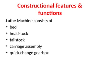
Types of Lathe
EngineLathe
The most common form of lathe, motor driven and
comes in large variety of sizes and shapes.
Bench Lathe
A bench top model usually of low power used to make
precision machine small work pieces.
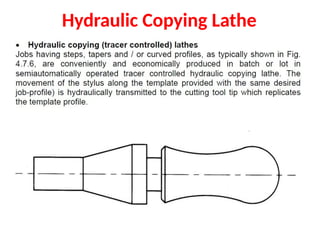
Tracer Lathe
a lathe that has the ability to follow a template to copy
a shape or contour.
5.
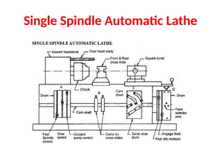
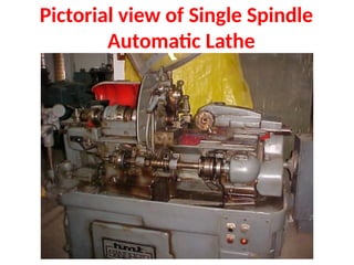
Automatic Lathe
A lathein which the work piece is automatically fed and removed
without use of an operator. Cutting operations are automatically
controlled by a
sequencer of some form
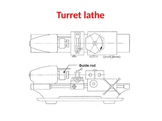
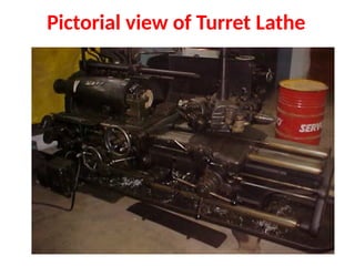
Turret Lathe
lathe which have multiple tools mounted on turret either
attached to the tailstock or the cross-slide, which allows for quick
changes in tooling and cutting operations.
Computer Controlled Lathe
A highly automated lathe, where both cutting, loading, tool
changing, and part unloading are automatically controlled by
computer coding.
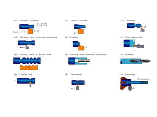
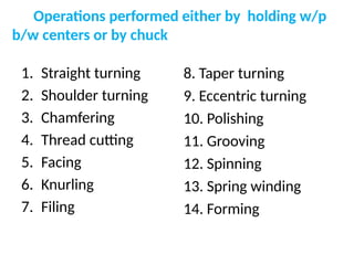
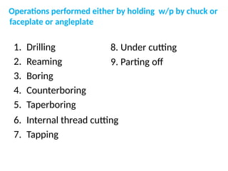
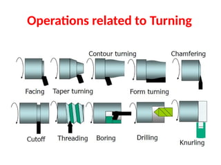
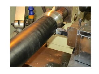
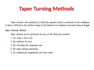
Operations on Lathe
Turning:produce straight, conical, curved, or grooved work pieces
Facing: to produce a flat surface at the end of the part or for making face grooves.
Boring: to enlarge a hole or cylindrical cavity made by a previous process or to produce
circular internal grooves.
Drilling: to produce a hole by fixing a drill in the tailstock
Threading: to produce external or internal threads
Knurling: to produce a regularly shaped roughness on cylindrical surfaces
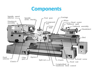
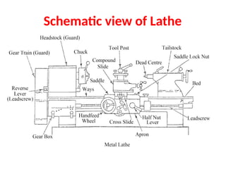
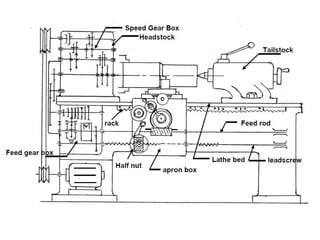
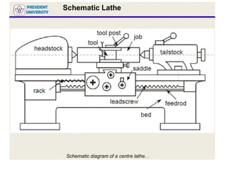
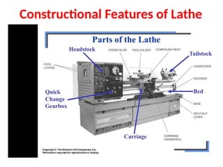
Bed made outof gray or ductile cast iron or fabricated from steel by
welding. Bed is divided to 2 types, first is the outer way and another one
is the inner way.
In the Inner way, headstock and tailstock located in it. By the longitudinal
movement for the carriage assembly and towards the centerline of the
lather. The bed is needed to clean to avoid damaging to the machine
Bed
21.
Headstock
• Headstock mountedon the left side of the lathe machine.
• the function of the headstock is to turn the work piece and where it is support to hold the
attachments mount.
• the spindle is mounted on the bearings on the headstock and it is hardened and specially
ground to fit different type of devices. Spindle speed is controlled by varying the geometry of
the drive train
• 3 jaw chucks, collets and centers can be held in the spindle
• To reverse the headstock movement, the lead screw and feed rod will change the direction of
the movement of the carriage
22.
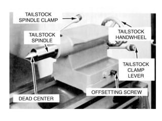
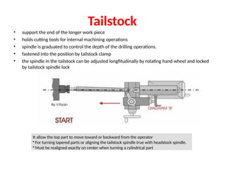
Tailstock
• support theend of the longer work piece
• holds cutting tools for internal machining operations
• spindle is graduated to control the depth of the drilling operations.
• fastened into the position by tailstock clamp
• the spindle in the tailstock can be adjusted longfitudinally by rotating hand wheel and locked
by tailstock spindle lock
It allow the top part to move toward or backward from the operator
• For turning tapered parts or aligning the tailstock spindle true with headstock spindle.
• Must be realigned exactly on center when turning a cylindrical part
23.
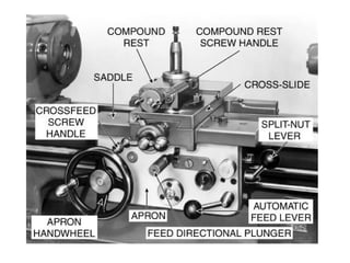
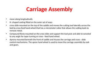
Carriage Assembly
• movealong longitudinally
• H- shaped casting fitted on the outer set of ways
• cross slide mounted on the top of the saddle and moves the cutting tool laterally across the
bed by cross feed hand wheel that has a micrometer collar that allows the cutting tools to
remove metal.
• Compound Resta mounted on the cross slide and support the tool post and able to swiveled
to any angle for taper turning or cross - feed hand wheel.
• Aprona mounted beneath the front of saddle and houses the carriage and cross - slide
control mechanisms. The apron hand wheel is used to move the carriage assembly by rack
and gears.
24.
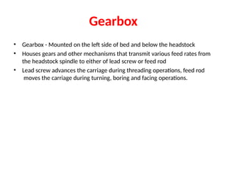
Gearbox
• Gearbox -Mounted on the left side of bed and below the headstock
• Houses gears and other mechanisms that transmit various feed rates from
the headstock spindle to either of lead screw or feed rod
• Lead screw advances the carriage during threading operations, feed rod
moves the carriage during turning, boring and facing operations.
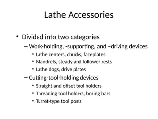
Chucks
• Used extensivelyfor holding work for
machining operations
– Work large or unusual shape
• Most commonly used lathe chucks
– Three-jaw universal
– Four-jaw independent
– Collet chuck
Four-Jaw Independent Chuck
•Used to hold round, square, hexagonal, and
irregularly shaped workpieces
• Has four jaws
– Each can be adjusted independently by chuck
wrench
• Jaws can be reversed to hold work by inside
diameter
Collet Chuck
• Mostaccurate chuck
• Used for high-precision work
• Spring collets available to hold round,
square, or hexagon-shaped workpieces
• Each collet has range of only few
thousandths of an inch over or under size
stamped on collet
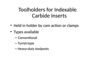
Toolholders for Indexable
CarbideInserts
• Held in holder by cam action or clamps
• Types available
– Conventional
– Turret-type
– Heavy-duty toolposts
42.
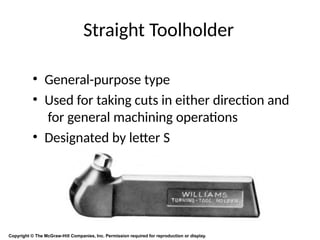
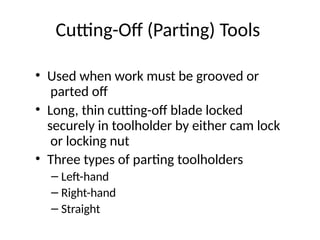
Cutting-Off (Parting) Tools
•Used when work must be grooved or
parted off
• Long, thin cutting-off blade locked
securely in toolholder by either cam lock
or locking nut
• Three types of parting toolholders
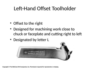
– Left-hand
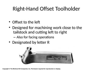
– Right-hand
– Straight
43.
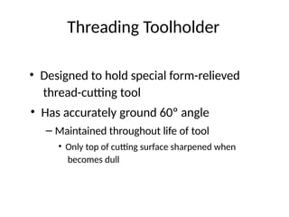
Threading Toolholder
• Designedto hold special form-relieved
thread-cutting tool
• Has accurately ground 60º angle
– Maintained throughout life of tool
• Only top of cutting surface sharpened when
becomes dull
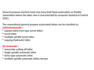
General purpose machinetools may have both fixed automation or flexible
automation where the latter one is characterized by computer Numerical Control
(CNC).
The conventional general purpose automated lathes can be classified as,
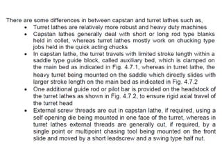
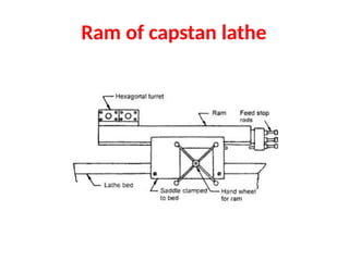
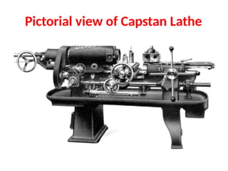
(a)Semiautomatic :
• capstan lathe (ram type turret lathe)
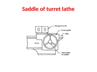
• turret lathe
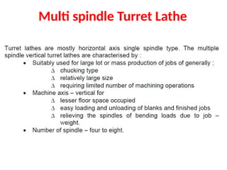
• multiple spindle turret lathe
• copying (hydraulic) lathe
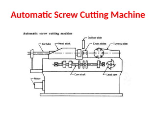
(b) Automatic :
• Automatic cutting off lathe
• Single spindle automatic lathe
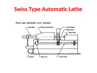
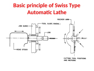
• Swiss type automatic lathe
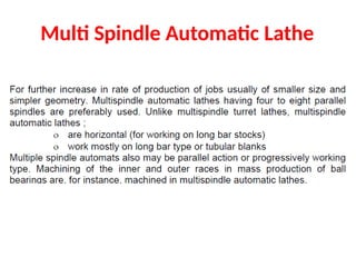
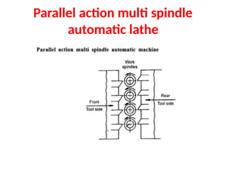
• multiple spindle automatic lathes Version
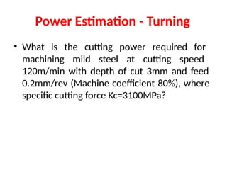
Power Estimation -Turning
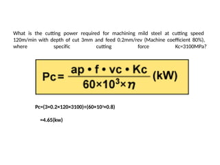
• What is the cutting power required for
machining mild steel at cutting speed
120m/min with depth of cut 3mm and feed
0.2mm/rev (Machine coefficient 80%), where
specific cutting force Kc=3100MPa?
81.
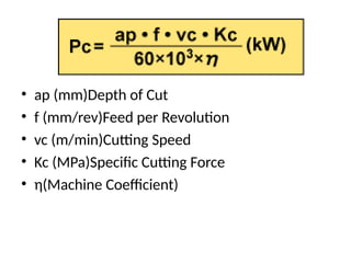
• ap (mm)Depthof Cut
• f (mm/rev)Feed per Revolution
• vc (m/min)Cutting Speed
• Kc (MPa)Specific Cutting Force
• η(Machine Coefficient)
82.
What is thecutting power required for machining mild steel at cutting speed
120m/min with depth of cut 3mm and feed 0.2mm/rev (Machine coefficient 80%),
where specific cutting force Kc=3100MPa?
Pc=(3×0.2×120×3100)÷(60×103×0.8)
=4.65(kw)
83.
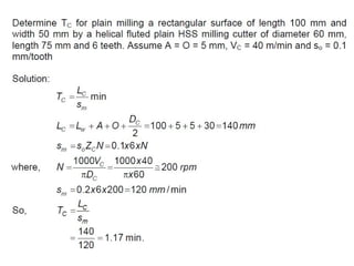
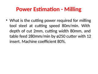
Power Estimation -Milling
• What is the cutting power required for milling
tool steel at cutting speed 80m/min. With
depth of cut 2mm, cutting width 80mm, and
table feed 280mm/min by ø250 cutter with 12
insert. Machine coefficient 80%.
84.
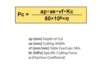
ap (mm) Depthof Cut
ae (mm) Cutting Width
vf (mm/min) Table Feed per Min.
Kc (MPa) Specific Cutting Force
η (Machine Coefficient)
85.
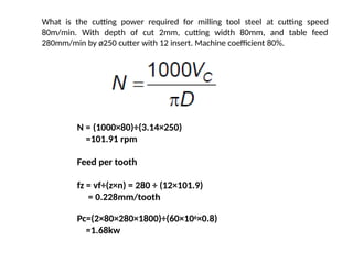
What is thecutting power required for milling tool steel at cutting speed
80m/min. With depth of cut 2mm, cutting width 80mm, and table feed
280mm/min by ø250 cutter with 12 insert. Machine coefficient 80%.
N = (1000×80)÷(3.14×250)
=101.91 rpm
Feed per tooth
fz = vf÷(z×n) = 280 ÷ (12×101.9)
= 0.228mm/tooth
Pc=(2×80×280×1800)÷(60×106×0.8)
=1.68kw