The document discusses mesh analysis and nodal analysis in electrical engineering, highlighting their methods for circuit analysis using Kirchhoff's laws. Mesh analysis focuses on loop currents and simplifies the number of equations, while nodal analysis uses node voltages, making it preferable in circuits with many current sources. Both methods provide structured approaches to solving circuits efficiently through matrix representations and equations.

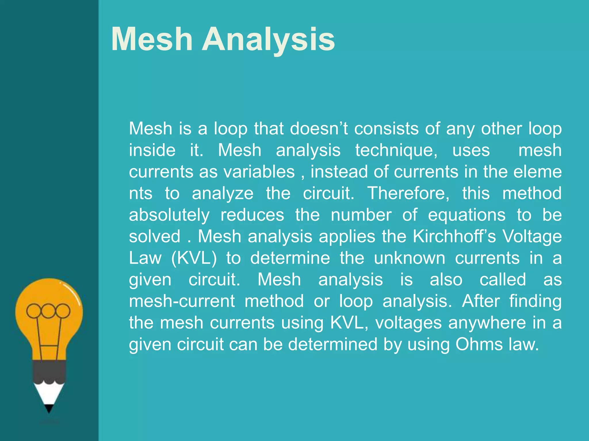


![Mesh Analysis
Where:
• [ V ] gives the total battery voltage for loop 1 and then
loop 2
• [ I ] states the names of the loop currents which we are
trying to find
• [ R ] is the resistance matrix
• [ R-1 ] is the inverse of the [ R ] matrix
and this gives I1 as -0.143 Amps and I2 as -0.429 Amps
As : I3 = I1 – I2
The combined current of I3 is therefore givens :
-0.143 – (-0.429) = 0.286 Amps
which is the same value of 0.286 amps, we found using
Kirchhoff's circuit law in the previous tutorial.](https://image.slidesharecdn.com/education-symbol-bulb-powerpoint-templates-standard-170510192628/75/Mesh-analysis-and-Nodal-Analysis-9-2048.jpg)
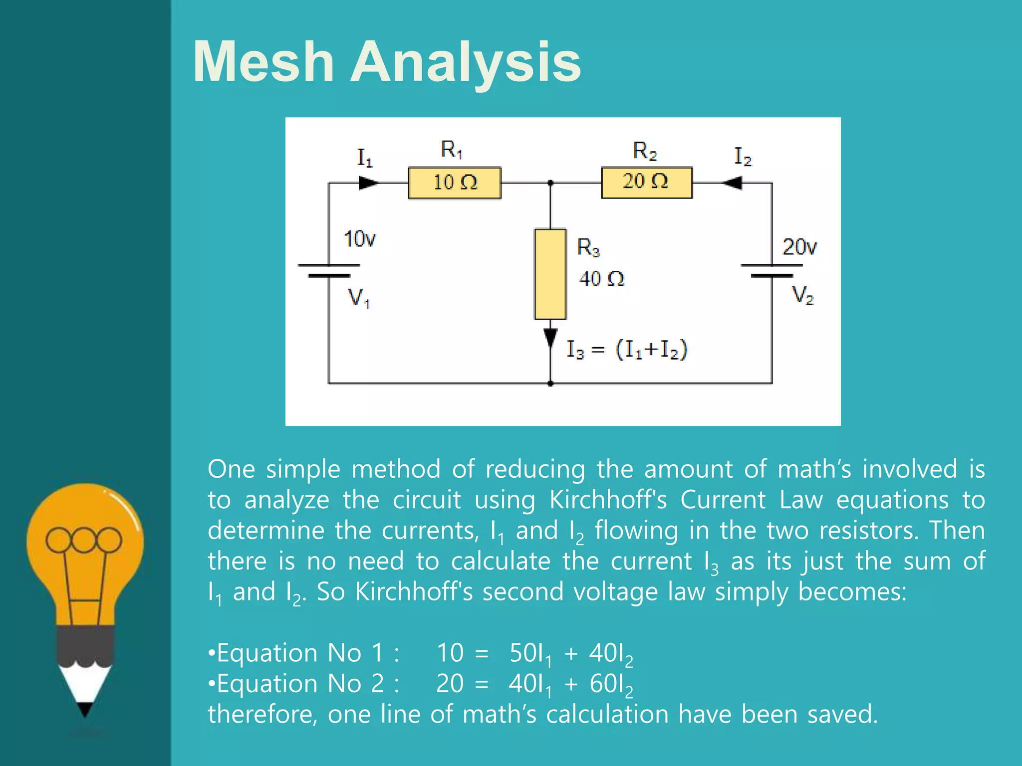
![Mesh Analysis
This “look-see” method of circuit analysis is probably the
best of all the circuit analysis methods with the basic
procedure for solving Mesh Current Analysis equations is
as follows:
1. Label all the internal loops with circulating currents.
(I1, I2, …IL etc)
2. Write the [ L x 1 ] column matrix [ V ] giving the sum of
all voltage sources in each loop.
3. Write the [ L x L ] matrix, [ R ] for all the resistances in
the circuit as follows;
• R11 = the total resistance in the first loop.
• Rnn = the total resistance in the Nth loop.
• RJK = the resistance which directly joins loop J to
Loop K.
4. Write the matrix or vector equation [V] = [R] x [I]
where [I] is the list of currents to be found.](https://image.slidesharecdn.com/education-symbol-bulb-powerpoint-templates-standard-170510192628/75/Mesh-analysis-and-Nodal-Analysis-10-2048.jpg)

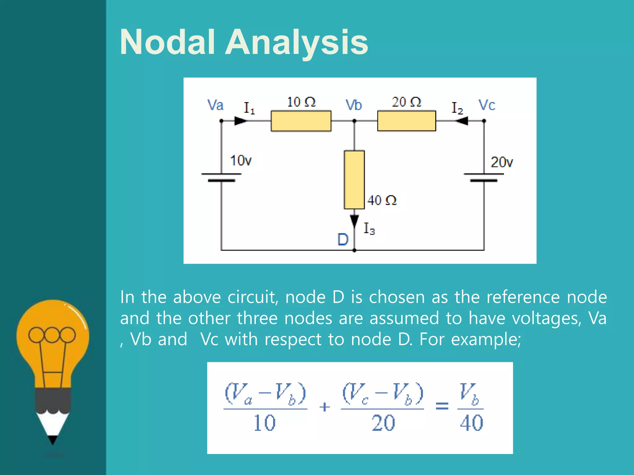
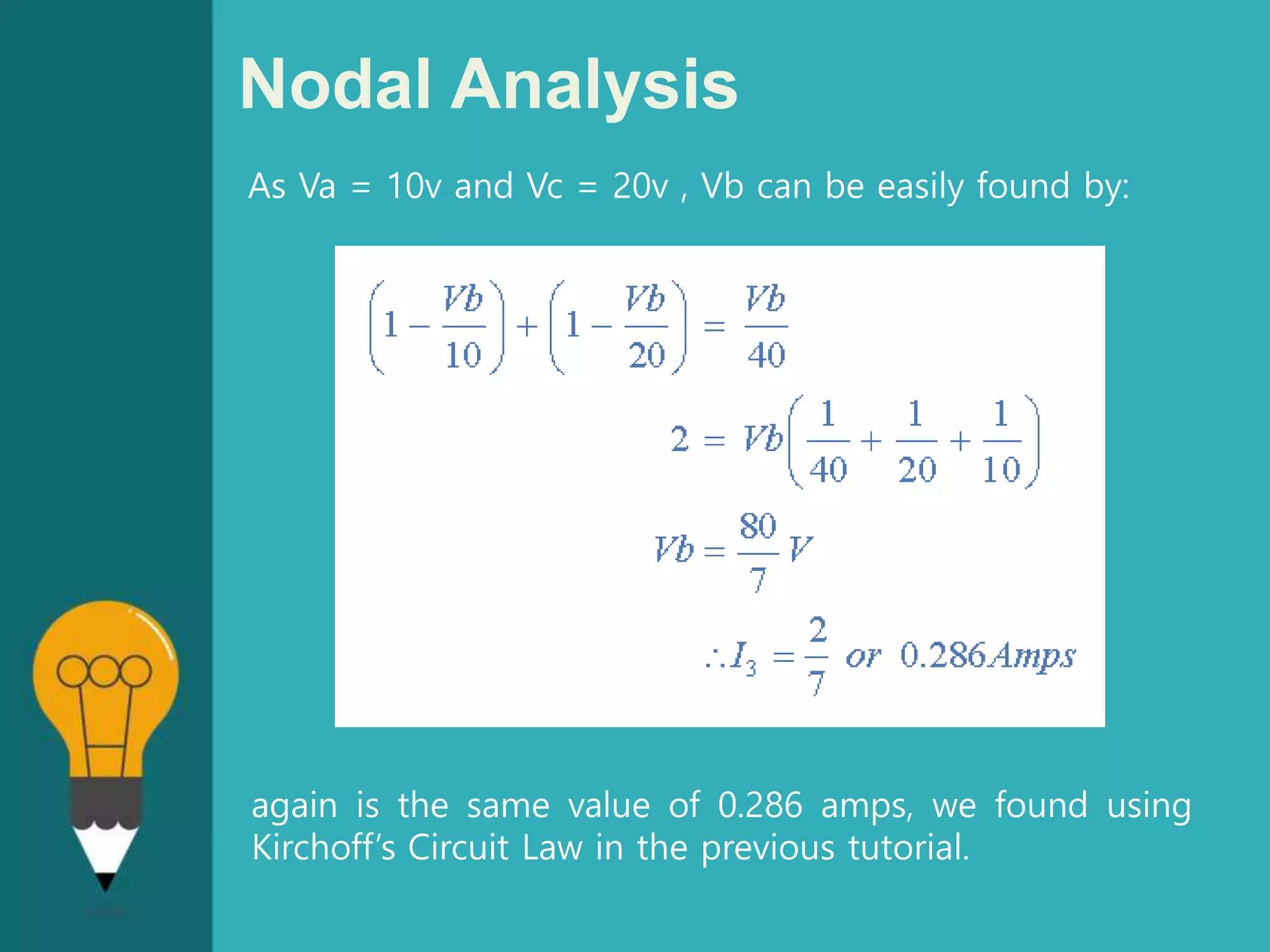
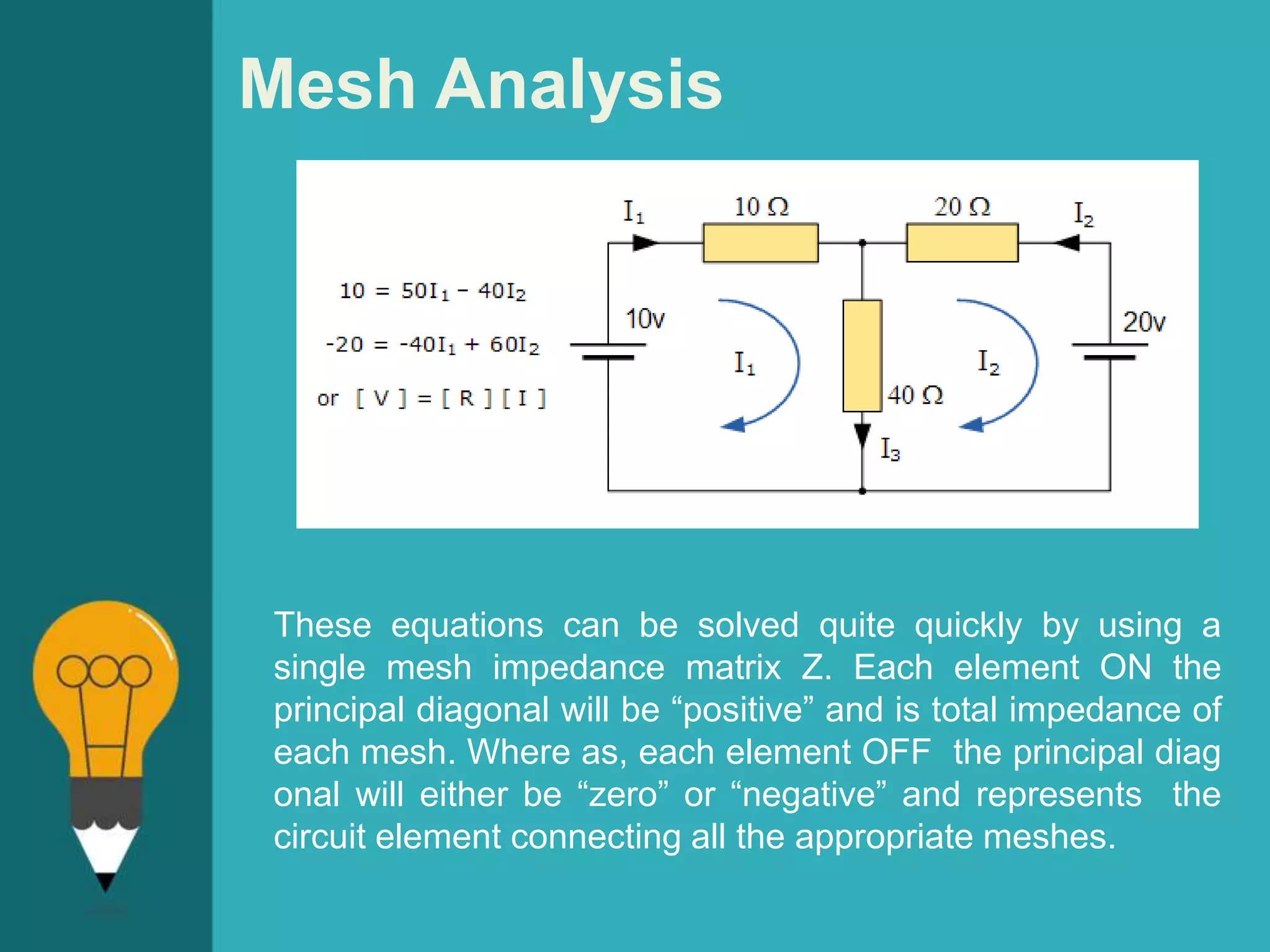
![Nodal Analysis
From both Mesh and Nodal Analysis methods we
have looked at so far, this is the simplest method
of solving this particular circuit. Generally, nodal
voltage analysis is more appropriate when there
are a larger number of current sources around. The
network is then defined as: [ I ] = [ Y ] [ V ] where
[ I ] are the driving current sources, [ V ] are the
nodal voltages to be found and [ Y ] is the
admittance matrix of the network which operates on
[ V ] to give [ I ].](https://image.slidesharecdn.com/education-symbol-bulb-powerpoint-templates-standard-170510192628/75/Mesh-analysis-and-Nodal-Analysis-15-2048.jpg)
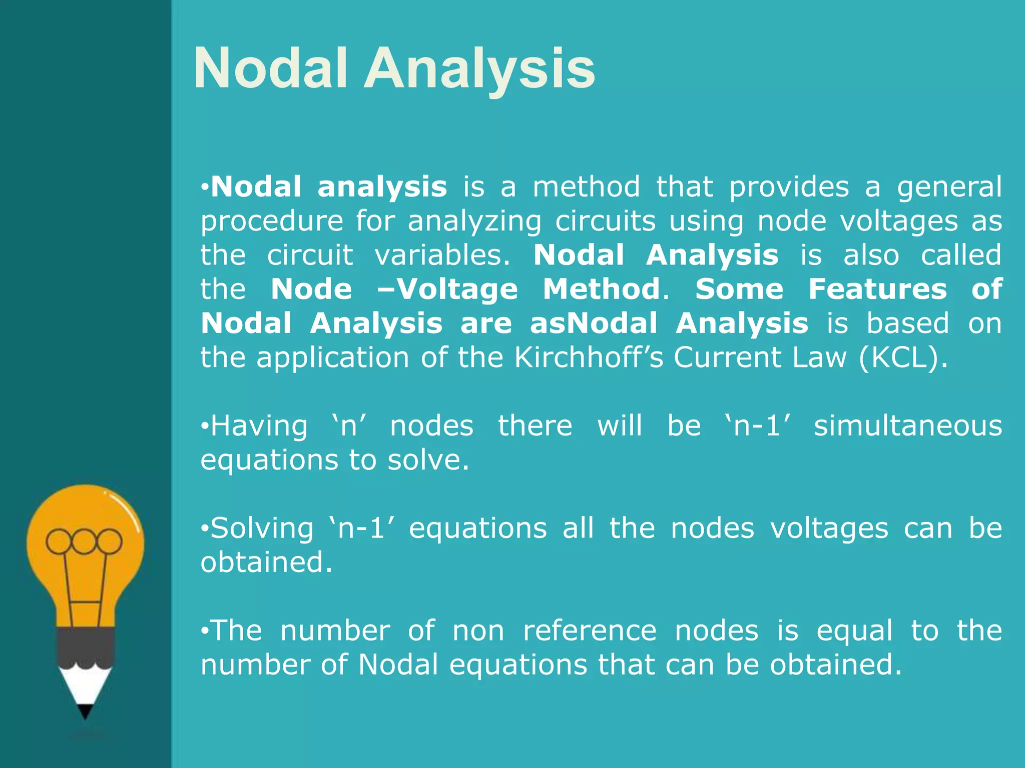
![Nodal Analysis
The basic procedure for solving Nodal Analysis equations is
as follows:
1. Write down the current vectors, assuming currents into a
node are positive. i.e, a (N x 1)
matrices for “N” independent nodes.
2. Write the admittance matrix [Y] of the network where:
• Y11 = the total admittance of the first node.
• Y22 = the total admittance of the second node.
• RJK = the total admittance joining node J to node K.
3. For a network with “N” independent nodes, [Y] will be an
(N x N) matrix and that Ynn will be positive and Yjk will be
negative or zero value.
4. The voltage vector will be (N x L) and will list the “N”
voltages to be found.](https://image.slidesharecdn.com/education-symbol-bulb-powerpoint-templates-standard-170510192628/75/Mesh-analysis-and-Nodal-Analysis-16-2048.jpg)