10 vat300 e_c4-1_rev_b
•Download as DOC, PDF•
0 likes•67 views

Khoa Học - Kỹ Thuật & Giải Trí: http://phongvan.org Tài Liệu Khoa Học Kỹ Thuật: http://tailieukythuat.info Thiết bị Điện Công Nghiệp - Điện Hạ Thế: http://dienhathe.vn

Recommended
More Related Content
What's hot
What's hot (17)
Similar to 10 vat300 e_c4-1_rev_b
Similar to 10 vat300 e_c4-1_rev_b (20)
More from Dien Ha The
More from Dien Ha The (20)
Recently uploaded
Recently uploaded (20)
10 vat300 e_c4-1_rev_b
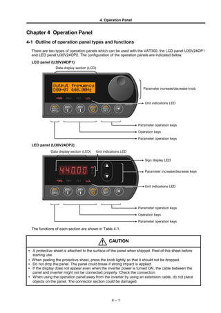
- 1. 4. Operation Panel Chapter 4 Operation Panel 4-1 Outline of operation panel types and functions There are two types of operation panels which can be used with the VAT300, the LCD panel U30V24OP1 and LED panel U30V24OP2. The configuration of the operation panels are indicated below. LCD panel (U30V24OP1) LED panel (U30V24OP2) The functions of each section are shown in Table 4-1. CAUTION • A protective sheet is attached to the surface of the panel when shipped. Peel of this sheet before starting use. • When peeling the protective sheet, press the knob lightly so that it should not be dropped. • Do not drop the panel. The panel could break if strong impact is applied. • If the display does not appear even when the inverter power is turned ON, the cable between the panel and inverter might not be connected properly. Check the connection. • When using the operation panel away from the inverter by using an extension cable, do not place objects on the panel. The connector section could be damaged. 4 – 1 Parameter increase/decrease knob Unit indications LED Data display section (LCD) Data display section (LED) Unit indications LED Sign display LED Parameter increase/decrease keys Unit indications LED Parameter operation keys Operation keys Parameter operation keys Parameter operation keys Operation keys Parameter operation keys
- 2. 4. Operation Panel Table 4-1 (1) Functions and operations of each operation panel section Status indications LEDs FWD (Forward) The drive is running in the forward direction. When both LEDs flicker simultaneously, it indicates that DC Brake or pre-excitation is in action. If only the "FWD" or "REV" LED is flickering, this indicates that a command in the reverse direction has been received, and the drive is decelerating. Refer to section 4-1-3 for the relation with the operation keys. REV (Reverse) The drive is running in the reverse direction. FLT (Fault) The drive has detected a fault and has stopped. Turns OFF when the + STOP RST MOD keys are pressed or the sequence input RESET signal is input. LCL (Local) The drive is in the Local Mode and can be operated from the Operation Panel (FWD, REV and STOP only). When LED is off, the drive is in the Remote Mode and can be controlled from the terminal block (sequence input signals). To change Modes between Local and Remote, press + STOP LCL SET . Change this setting while operation is stopped. Unit indication LEDs (LED panel dedicated) Hz・A・% Indicates the unit of the parameter value shown on the display. Minus polarity indication LED (LED panel dedicated) —— Lights when the number on the display is a minus number. Operation keys Starts the drive in the forward direction. (in Local Mode only) Starts the drive in the reverse direction. (in Local Mode only) Stops the drive. The motor will either coast to a stop or ramp down to a stop as selected on C00-1. Held down for 2 sec. When this key is held down for two seconds or longer during operation, the motor will coast to stop regardless of Local Mode or Remote Mode. + STOP LCL SET Changes control Modes from Local to Remote, or vice-versa. When the drive is in Local Mode, "LCL" LED is on. The drive is default set so that a Local/Remote selection is disabled while the drive is running. Even while the drive is at a stop, this selection cannot be made if operating commands such as RUN, JOG, etc., are being received at the terminal. This lock can be released with Parameter C09-2. + STOP RST MOD If these keys are pressed simultaneously when the FLT LED is ON, the FLT LED will turn OFF. (Fault is reset.) Parameter operation keys ・ Parameter operation knob RST MOD Changes the block No. mode displayed on the indicator in the following order each time the key is pressed: Monitor → Parameter A → Parameter B → Parameter C → Utility Mode U. LCL SET Fixes Parameter number or set its values. Param. Select When main & sub-No. selection method (C11-7=2) is selected for parameter setting method, moves from sub-No. selection to main No. selection. Valve change Moves the digit to increment or decrement. 4 – 2
- 3. 4. Operation Panel Table 4-1 (2) Functions and operations of each operation panel section Parameter increase/decrease key, parameter increase/decrease knob or Increases the parameter No. or parameter setting value. or Decreases the parameter No. or parameter setting value. or+ When the parameter is being set with the sub-No. selection method (C11- 7=1), increases the parameter's main No. + or When the parameter is being set with the sub-No. selection method (C11- 7=1), decreases the parameter's main No. Operations dedicated for LED panel Held down Increases the parameter No. or setting value at a fast speed. Held down Decreases the parameter No. or setting value at a fast speed. 4-1-1 Data display section on each panel Each value display is explained in this section. The LCD panel displays the characters, parameters and setting values with a 5*8 dot, 16-digit * 2-line LCD. The LCD panel's LCD section is expressed with the following box in this manual. Out put f r e que nc y D00- 0: OFF. Hz The LED panel displays the parameters and setting values with a 7-segment 5-LED + sign display LED. The LED panel's 7-segment section is expressed with the following display in this manual. A % Hz 4 – 3
- 4. 4. Operation Panel 4-1-2 Relation of RUN operation keys and status display LED The status display LED turns ON, OFF or flickers according to the FWD and REV operation status. Each operation is shown in the following figure. Refer to the right drawing for the status of FWD and REV in the figure. Panel key FWD Panel key REV Stop StopForward Forward→ Reverse Reverse Reverse→ Forward Forward Decelera- tion stop Braking FWD, REV display Operation Panel key STOP Output frequency (speed) FWD FWD FWD FWD REV REV REV REVREV FWD FWD FWD REV FWD FWD FWD REV REV Fig 4-1-2 Relation of panel key, RUN operation and FWD, REV 4-1-3 Selecting the operation method Two operation methods can be selected with the operation panel by setting the parameters. The parameters to be set and the operation methods are explained below. C11-7: Operation panel operation method selection =1: Sub-No. selection method Increase or decrease the parameter's sub-No. with the keys or . If the sub-No. exceeds the maximum value or minimum value, the main No. will increase or decrease by 1. This method is easy to use when holding the panel in hand and operating. * This method is the default method. =2: Main & sub-no. selection method The parameter is set by setting both the main No. and sub-No. After entering the main No., press the LCL SET key to enter the sub-No. selection. If the sub-No. exceeds the maximum value or minimum value, the number will loop within the sub-No. 4 – 4 Status Display OFF ON Flicker F W D REV F W D F W D REV REV
- 5. 4. Operation Panel 4-1-4 Panel display at power ON (1) LCD operation panel (U30V24OP1) The following display appears when the power is turned ON. (2) LED operation panel (U30V24OP2) When the power is turned ON, all LEDs on numeric display will light momentarily, and then " ", " " will appear. Finally, " " will appear. With either operation panel, the initial operation mode (C11-0) at power ON and the initially displayed parameters can be set (C11-3). In the above example, C11-0 is set to 1, and C11-3 is set to 0.00.0. CAUTION • If the normal end or initial fault occurrence screen does not appear even after 10 seconds, check the following points. 1) Are the panel and inverter connected correctly? Remove the panel once, and securely connect it. 2) Is the cable connecting the PCB in the inverter and the panel disconnected? Check and securely insert the connector. • If the problem cannot be resolved with method 1) or 2), there may be an error in the inverter's internal circuit. Turn the power OFF immediately. 4 – 5 V24O P1 RO M 1 O u t p u t f r e q u e n c y D 00- 0: O F F. H z Normal displayOperation panel operation check FW D REV FLT LCL FW D REV FLT LCL FW D REV FLT LCL Operation panel ROM version display Hz A % LCLFWD REV FLT
- 6. 4. Operation Panel 4-2 Various operations and displays when LCD panel is connected The various LCD panel operations and displays are displayed. First, the various operation methods and displayed for the sub-No. selection method (C11-7=1) are explained. 4-2-1 Details of data display section The outline of the Main screen is shown below. Out put f r e que nc y D00- 0: OFF. Hz Character display section The details of the parameters are displayed. The default setting is English. Parameter display section The parameter No. is displayed. Setting value display section The setting value or display value is displayed. The parameter numbers are categorized in the following manner in this manual. D00-0 Sub-No. Main No. Block No. 4-2-2 Operating and displaying the character display section The character display section starts left scrolling after two seconds. When the last character is displayed, the display remains for two seconds, and then the first display appears. Out put f r e que nc y D00- 0: OFF. Hz f r e que nc y i n Hz D00- 0: OFF. Hz put f r e que nc y i n D00- 0: OFF. Hz Head display (two seconds) Character display scrolling to left Last character display (two seconds) After displaying the last character display for two seconds, the head display appears The character display can be selected from five languages, English, French, Italian, Spanish or German. Change the language with the parameter C11-4 setting value. The default language is English. Refer to section 4-2-5 Setting value operation and display for details on changing the setting value. 4 – 6
- 7. 4. Operation Panel 4-2-3 Operating and displaying parameter numbers The flicking character can be displayed. The parameter No. will increase when the parameter increase/decrease knob is turned to the right, and will decrease when the knob is turned to the left. Out put f r e que nc y D00- 1: OFF. % Out put f r e que nc y D00- 4: OFF. Out put f r e que nc y D00- 0: OFF. Hz Increases when turned rightDecreases when turned left Current display Only the parameter No. is displayed when the parameter increase/decrease knob is being turned. The setting value appears 0.1s after the knob is stopped. The characters on the upper line will start to scroll at the same time. D00- 1 Out put f r e que nc y D00- 0: OFF. Hz First display Out put f r e que nc y D00- 1: OFF. % Immediately after change Display 0.1 seconds after no key input 0.1 seconds 4-2-4 Changing the block No. If the RST MOD key is pressed when the parameter No. is displayed or when setting the setting value, the block will change in the order of D → A → B → C → U → D. Rat e d i nput vol t B00- 0: 7. Run Command me t h C00- 0: 1. RST MOD U00- 0En U00- 0: 0. RST MOD Out put f r e que nc y D00- 0: OFF. Hz Loc al f r e que nc y A00- 0: 10. 00Hz RST MOD RST MOD RST MOD 4-2-5 Operating and displaying setting values If the LCL SET key is pressed when the Block- A, B, C or U is displayed, the operation will shift to the setting value setting. The flickering character moves to the setting value side. Loc a l f r e que nc y A00- 0: 10. 00Hz LCL SET Loc a l f r e que nc y A00- 0: 10. 00Hz Current display Shifts to setting value setting When setting the setting value, the value can be increased and decreased by turning the parameter increase/decrease knob. Loc al f r e que nc y A00- 0: 10. 00Hz Loc al f r e que nc y A00- 0: 10. 01Hz Loc al f r e que nc y A00- 0: 9. 99Hz Current display Increases when turned rightDecreases when turned left 4 – 7
- 8. 4. Operation Panel When the key is pressed, the digit to be changed (flickering character) can be moved one digit to the left. If the key is pressed when the flickering character is at the top digit, it will move to the last digit. Loc al f r e que nc y A00- 0: 10. 00Hz Loc al f r e que nc y A00- 0: 10. 00Hz Loc al f r e que nc y A00- 0: 10. 00Hz Loc al f r e que nc y A00- 0: 10. 00Hz When the setting value has been decided, press the LCL SET key again to enter the setting value. The character to be changed will also move to the parameter No. Loc al f r e que nc y A00- 0: 12. 34HzLCL SET Loc al f r e que nc y A00- 0: 12. 34Hz Current display Moves to parameter No. selection To return to the parameter No. selection without changing the parameter with setting value setting, press the RST MOD key. The display will change to the next block No. If the parameter for which the setting value was being changed is moved to, the setting value will return to the original value. Note that the value will not return for A00-0: direct frequency setting and A00-2: direct speed setting. Max. f r e que nc y( v B00- 4: 50. 00Hz Max. f r e que nc y( v B00- 4: 80. 00Hz Run Comma nd me t h C00- 0: 1. RST MOD U00- 0En U00- 0: 0. RST MOD Out put f r e que nc y D00- 0: OFF. Hz Loc a l f r e que nc y A00- 0: 10. 00Hz RST MOD RST MOD RST MOD Max. f r e que nc y( v B00- 4: 50. 00Hz LCL SET Setting value change Returns to original parameter 4 – 8
- 9. 4. Operation Panel 4-2-6 Operating and displaying parameter numbers with main and sub-No. selection method An example of operations when C11-7=2: main & sub-No. selection method is explained in this section. Out put f r e que nc y D00- 1: OFF. % Se t f r e que nc y i n D01- 0: 10. 00Hz Out put f r e que nc y D00- 0: OFF. Hz Out put f r e que nc y D00 Fr e que nc y s e t t i n D01 LCL SET Out put f r e que nc y D00- 2: OFF. % Out put f r e que nc y D00- 4: OFF. Se t f r e que nc y/s e D01- 4: 300. Se t f r e que nc y i n D01- 1: 20. 00% LCL SET Out put c ur r e nt ( A D02 Initial display With this method, if the digit to be changed (flickering character) is at the parameter number's sub-No. and the parameter increase/decrease knob is turned, the main No. will not change, and only the sub-No. will change. To move from the sub-No. selection to the main No., press the key. The digit to be changed will move to the main No. If the parameter increase/decrease knob is turned when the digit to be changed is at the main No., the main No. will be changed. To move from the main No. selection to the sub-No. selection, press the LCL SET key. The digit to be changed will move to the sub-No. If the LCL SET key is pressed again when the sub-No. is selected, the display will change to the setting value setting. Refer to section 4-2-5 operating and displaying the setting value, and set the setting value. 4 – 9
- 10. 4. Operation Panel 4-2-7 Displaying the sequence With the LCD panel, the D04-0 to 3: sequence input and D04-4 to 7: sequence output are displayed as shown below. The D04-4: Sequence output 1 is shown as a display example. D04- 4: Se que nc e s t at us - ○ and | indicate the status of the corresponding sequence. ○ : Sequence OFF | : Sequence ON ○ and | are updated immediately when the sequence status changes. Example : Start of operation (Sequence output: RUN, ATN ON) 4-2-8 Displaying the fault history When the parameter is set to D20-0 and the LCL SET key is pressed, the fault history display will appear. To return to the parameter selection from the fault history display status, press the LCL SET key again, or press the RST MOD key. Pr i mar y e r r or c o E00 : UV- 2. LCL SET Fa ul t hi s t or y mo D20- 0: 「ERR」 or RST MOD LCL SET Current display Moves to the fault history display If the parameter increase/decrease knob is turned in the fault history display status, the numbers will loop between E00 and E37, and the fault corresponding to the number will display. Refer to section 4-3-7 Fault history display for details on E00 to E37. Pr i mar y e r r or c o E00 : OV- 4. Se c ondar y e r r or E01 : - - - . Out put f r e qua r y E02 : 43. 98Hz Out put c ur r e nt o E03 : 61. 2A DC vol t age on f a E04 : 746. V Cumul a t i ve c ondu E06 : 246. h E05 : Faul t i nf omat i o Cumul a t i ve r un t E07 : 234. h Pr i mar y e r r or c o E10 : UV- 2. Primary fault Secondary fault Frequency value at fault Current value at fault DC voltage value at fault Hardware fault signal at fault Cumulative power ON time at fault Cumulative operation time at fault Primary fault 4 – 10 Start of operation D04- 4: Se que nc e s t a t us - D04- 4: Se que nc e s t at us -
- 11. 4. Operation Panel 4-2-9 Operating and displaying during Block-A, B, C parameter change list selection If the LCL SET key is pressed when the parameter is set to D20-2, the Block-A, B, C parameter change list will appear. Press the RST MOD key to return to the parameter selection from the Block-A, B, C parameter change list display. LCL SET Par ame t e r A, B a D20- 2: 「LST」 RST MOD D. CHG: D. END Current display Moves to Block-A, B, C parameter change list display If the parameter increase/decrease knob is turned while the Block-A, B, C parameter change list is displayed, the parameters which were set or changed after power ON will appear in sequence. If the LCL SET key is pressed in this state, the display will change to parameter setting value setting. The setting value can be changed in this state. If the LCL SET key is pressed again, the change list will reappear. If the parameter increase/decrease knob is pressed to the last of the changed parameters, "D.CHG: D.END" will appear. If the parameter increase/decrease knob is pressed further, the first parameter will appear. DC br aki ng t i me A03- 1: 3. 0s Max. f r e que nc y( V B00- 4: 60. 00Hz R. RUN Re ve r s e Ru C03- 2: 6. D. CHG: D. END DC br aki ng t i me A03- 1: 3. 0s Max. f r e que nc y( V B00- 4: 60. 00Hz R. RUN Re ve r s e Ru C03- 2: 6. LCL SET LCL SET LCL SET 4 – 11
- 12. 4. Operation Panel 4-2-10 Displaying the LCD panel dedicated sequence characters If the LCL SET key is pressed when the parameter is set to D20-3 or 4, the sequence input or output display will appear. The parameter No. and target are shown below. D20-3 : Sequence input D20-4 : Sequence output The D20-4 sequence output is explained as an example in the following section. The operations are the same for D20-3 and 4. To return to parameter selection, press the LCL SET key or RST MOD key. RUN : OFF. FLT : OFF. Initial display LCL SET Se que nc e out put D20- 4: 「SEQOUT」 or RST MOD LCL SET Display for sequence output If the parameter increase/decrease knob is turned while the sequence details are displayed, the display will move up and down. MPO8 : OFF. RUN : OFF. FLT : OFF. MC : ON. RDY1 : ON. Display area The display area shifts up or down by one line when parameter increase/decrease knob is turned. Refer to Chapter 6 List of Parameters for the names of the displayed sequences. The ON and OFF status is updated immediately when the sequence status changes. Example : Start of operation (Sequence output: RUN is ON) RUN : OFF. FLT : OFF. RUN : ON. FLT : OFF.Start of operation 4 – 12
- 13. 4. Operation Panel 4-2-11 LCD panel display at fault occurrence, and resetting methods When a fault occurs in the inverter, the following type of display will appear on the LCD panel. Loc al f r e que nc y D00- 0: - 56. 32Hz Pr i mar y e r r or c o E00 : UV- 2. REVFWD FLT LCL FLTFWD LCLREV Current display Moves to fault history display simultaneously with fault occurrence Fault occurrence When a fault occurs, the inverter operation stops, and the "FLT" LED on status display LED turns On. At the same time, the head "E00" for the fault history and the fault code appear on the LCD panel. The cause of the fault is indicated at the fault code displayed at E00 to E07. Refer to Appendix Table 3 Fault codes for details on the fault codes. In the above figure, an undervoltage occurred during constant speed operation and a fault occurred. If the parameter increase/decrease knob is turned while the history is displayed, the fault details can be displayed in the range of E00 to E37. To return to the normal parameter selection from the fault history display, press the RST MOD key. Resetting a fault: Refer to the details of E00 to E07 in the fault history display and the Appendix Table 3 Fault code table, and remove the cause of the fault. The FLT LED will turn OFF when the + STOP RST MOD keys are pressed or the sequence input RESET is turned ON. Refer to Chapter 5 section 5-3 Programmable sequence input function (PSI) for details on resetting the fault with the sequence input RESET. The display in this case is shown below. Loc al f r e que nc y D00- 0: OFF. Hz Pr i mar y e r r or c o E00 : UV- 2. FWD FLT LCLFLTFWD LCLREV REV + STOP RST MOD Current display The D monitor parameter displayed just before the fault occurred is returned to with fault reset. Fault reset When the fault is reset, the LCD panel display will return to the D monitor parameter from the fault history state. Confirm that the cause of the fault has been removed, and then resume operation. 4 – 13