Manual heatit z-water_analog inputs_fw 2.1_ver2019-a_eng
•
0 likes•1,797 views

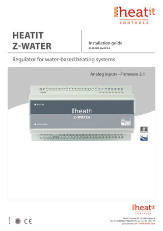
Heatit Z-Water is a DIN-rail regulator for controlling hydronic heating. is equipped with 10 relay outputs and it has 4 analog/digital inputs. Can be used for on/off control of light, control of valve actuators for an underfloor heating system.

Recommended
More Related Content
What's hot
What's hot (20)
Similar to Manual heatit z-water_analog inputs_fw 2.1_ver2019-a_eng
Similar to Manual heatit z-water_analog inputs_fw 2.1_ver2019-a_eng (20)
More from Domotica daVinci
More from Domotica daVinci (20)
Recently uploaded
Recently uploaded (20)
Manual heatit z-water_analog inputs_fw 2.1_ver2019-a_eng
- 1. Ver2019-A 2 yr HEATIT Z-WATER Installation guide 01.03.2019 Ver2019-A Regulator for water-based heating systems Analog inputs - Firmware 2.1 Heatit Controls AB, SE-Läkarvägen 4 454 31 BRASTAD, SWEDEN, Phone: +47 61 18 77 77 post@heatit.com – www.heatit.com
- 2. 1. PRODUCT DESCRIPTION 2. INSTALLATION GUIDELINES 2.1 Inputs 2.2 Relay Outputs 2.3 24V DC Output 3. BEHAVIOUR WITHIN THE Z-WAVE NETWORK 4. ADD/REMOVE 5. FACTORY RESET 6. ASSOCIATION GROUPS 7. SECURITY (S2) 8. CONFIGURATION PARAMETERS 9. COMMAND CLASSES 10. TECHNICAL SPECIFICATION 3 3-5 5 5 5 6 7 8 10 11 CONTENTS
- 3. 3 1. PRODUCT DESCRIPTION Heatit Z-Water is a regulator that clips right onto a DIN rail to add a variety of functions to you wireless Z-Wave network. Heatit Z-Water is equipped with 10 relay outputs and 4 analog inputs, and a Z-Wave radio for interfacing to the wireless Z-Wave network. The regulator can be power supplied from a 230V AC mains connection, and is able to deliver an output supply of 24V DC. Heatit Z-Water relay outputs are able to be freely controlled from the Z-Wave network, and can be used for several purposes, e.g. on/off control of light, control of valve actuators for an underfloor heating system, or control of other home automation systems. Heatit Z-Water inputs are analog inputs for interfacing simple temperature sensors; NTC, PT1000, etc. It is possible to configure the level and the indication of the status indicator LED in the front of the Heatit Z-Water regulator. 2. INSTALLATION GUIDELINES ATTENTION: only authorized technicians under consideration of the country-specific installation guidelines/norms may do works with 230 Volt mains power. Prior to the assembly of the product, the voltage network has to be switched off and ensured against re-switching. Use the following procedure to install Heatit Z-Water: 1. Use a flat object (such as a flat-head screwdriver) to pull the DIN rail release tab downward. 2. Place the top of the Heatit Z-Waterrail mount over the top of the DIN rail. 3. Tilt the bottom of the Heatit Z-Water toward the DIN rail until it snaps into place.. NOTE: WHEN MOUNTING DIN RAIL PRODUCTS, USE A FLAT-HEAD SCREWDRIVER TO PULL THE DIN RAIL RELEASE TAB WHILE SNAPPING THE DEVICE ONTO THE DIN RAIL. Make any necessary connections to the device, and apply power after all connections have been made. PREPARING AND CONNECTING WIRES When making connections, strip the ends of the wires approximately 6 mm. Use care to avoid nicking the conductors. Tighten the connector to 0.5 Nm. The wire gauge should be 12 to 30 AWG.
- 4. 4 230V AC Power Supply Terminals for connecting the 230V AC mains power supply. The module has an internal fuse that can replaced by opening the cover of the module, please see Technical Specification section for which type of fuses that can be used. Analog Inputs Terminals for the 4 analog inputs. 24V DC Supply Outputs Terminals for the 24V DC power supply output that can be used to be switched through the relay outputs. Relay Outputs Terminals for the 10 relay outputs, with 2 screw terminals for each output, a Common and Normally Open terminal. 2.1. Inputs The inputs of Heatit Z-Water is analogue temperature inputs and the type of the connected thermistor can be selected by means of a configuration parameter for each of the inputs. See configuration parameters 3, 4, 5 and 6.When these parameters are supplied in the configuration parameters for the input, then the input will be able to be used as a temperature measuring input, and the sensor devices in Heatit Z-Water will be able to report the temperatures as Multilevel Sensor values. NB! The inputs are per default not configured to any type of thermistor, so in order to make an input able to report temperature measuring it must be configured to the appropriate thermistor type. See configuration parameters 3, 4, 5 and 6. 2.2. Relay Outputs Heatit Z-Water relay outputs are Normally-Open relay contact outputs, that can be used to switch the supply voltage to different kind of loads, see the technical specification for types of supported loads. LHC5030 Installation- 2.1. Inputs. The inputs can be used for controlling other Z-Wave devices by means of transmitting different class messages. See the association groups for the input devices. The trigger level of the digital input can be configured to either be level-, positive edge- or nega triggered. 2.2. Relay Outputs. LHC5030 relay outputs are Normally-Open relay contact outputs, that can be used to switch th voltage to different kind of loads, see the technical specification for types of supported loads. Above schematic outlines how the relay outputs are implemented internally. CONNECTIONS In the drawing below is the different module connections shown. s STATUS INCLUSION www Analog InputsPower Supply Schematic outlines of how the relay outputs are implemented internally
- 5. 5 2.3. 24V DC Output Heatit Z-Water is supplied with a 24V DC output that can be used for supplying power to the loads that can be connected to relay outputs. The supply can, for example be used for powering 24V valve actuators. See the section with technical specifications for the performance of the 24V power supply. Schematic outline example of how the 24V supply output, together with a relay output, can be used to control a load. 3. BEHAVIOUR WITHIN THE Z-WAVE NETWORK This product can be operated in any Z-Wave network with other Z-Wave certified devices from other manufacturers. All non-battery operated nodes within the network will act as repeaters regardless of manufacturer to increase reliability of the network. On delivery, the device does not belong to any Z-Wave network. The device needs to be added to an existing wireless network to communicate with the devices of this network. Devices can also be removed from a network. Both adding and removing processes are initiated by the primary controller of the Z-Wave network. This controller will enter a mode for adding or removing devices. The device can only be added or removed from the network if the primary controller is in add/remove mode. When the device is removed from the network, the device will revert to factory default settings. 4. ADD/REMOVE Please refer to your primary controller manual on how to enter add/remove mode. The device can only be added or removed from the network if the primary controller is in add/remove mode. When the primary controller is set to add/remove modus press the ”INCLUSION”button once on the device. If the device already belongs to a network, follow the removing process before adding it in your network. Otherwise, the adding of this device will fail. When the device is removed from the network, the device will revert to factory default settings. 5. FACTORY RESET Heatit Z-Water can be factory reset by pressing the small button through the little hole, marked with the text“INCLUSION”, in front of the Heatit Z-Water regulator for at least 10 seconds. NOTE: ONLY USE THIS PROCEDURE WHEN THE PRIMARY NETWORK CONTROLLER IS MISSING OR IS OTHERWISE INOPERABLE. LHC5030 Installation- and user manual Logic Home Control Page 6 / 16 Above schematic outlines an example of how the 24V supply output, together with a relay output, can be used to control a load.
- 6. 6 6. ASSOCIATION GROUPS From a Controller’s point of view, Heatit Z-Water will consists of a root device and 14 endpoint devices - if the Controller is supporting Multichannel devices, otherwise is only the root device seen by the Controller (endpoint 0). The devices are: • Root device; an intersection of all the devices (endpoint 0). • 10 switch devices to control each of the relay outputs (endpoint 1 – 10). • 4 sensor devices representing the analogue inputs (endpoint 11 – 14). Below is an overview of all the devices and the association groups for each device. The first number in the association group number indicates the group number for actual device, and the second number is the group number on the root device (endpoint 0). DEVICE 1 (ENDPOINT 1) RELAY OUTPUT 1 Group 1 / 1 Lifeline. Sends Device Reset notifications and Basic Report On / Off when relay output 1 is activated. Max. nodes in the group: 5 DEVICE 2 (ENDPOINT 2) RELAY OUTPUT 2 Group 1 / - Lifeline. Sends Basic Report On / Off when relay output 2 is activated. Max. nodes in the group: 5 DEVICE 3 (ENDPOINT 3) RELAY OUTPUT 3 Group 1 / - Lifeline. Sends Basic Report On / Off when relay output 3 is activated. Max. nodes in the group: 5 DEVICE 4 (ENDPOINT 4) RELAY OUTPUT 4 Group 1 / - Lifeline. Sends Basic Report On / Off when relay output 4 is activated. Max. nodes in the group: 5 DEVICE 5 (ENDPOINT 5) RELAY OUTPUT 5 Group 1 / - Lifeline. Sends Basic Report On / Off when relay output 5 is activated. Max. nodes in the group: 5 DEVICE 6 (ENDPOINT 6) RELAY OUTPUT 6 Group 1 / - Lifeline. Sends Basic Report On / Off when relay output 6 is activated. Max. nodes in the group: 5 DEVICE 7 (ENDPOINT 7) RELAY OUTPUT 7 Group 1 / - Lifeline. Sends Basic Report On / Off when relay output 7 is activated. Max. nodes in the group: 5 DEVICE 8 (ENDPOINT 8) RELAY OUTPUT 8 Group 1 / - Lifeline. Sends Basic Report On / Off when relay output 8 is activated. Max. nodes in the group: 5 DEVICE 9 (ENDPOINT 9) RELAY OUTPUT 9 Group 1 / - Lifeline. Sends Basic Report On / Off when relay output 9 is activated. Max. nodes in the group: 5 DEVICE 10 (ENDPOINT 10) RELAY OUTPUT 10 Group 1 / - Lifeline. Sends Basic Report On / Off when relay output 10 is activated. Max. nodes in the group: 5
- 7. 7 7. SECURITY (S2) The S2 security enhances Z-Wave Plus with an additional layer of AES 128-bit encryption of the wireless Z-Wave communication in order to prevent hacking and man-in-middle attacks of the home network. The Heatit Z-Water supports S2 and has a QR-code label that can be used when the module is included into the Z-Wave home network. The including Controller will ask for a 5-digit code, which can be identified beneath the QR-code, and will then ask to confirm the rest of the code that is contained in the QR-code. DEVICE 11 (ENDPOINT 11) ANALOGUE INPUT 1 Group 1 / - Lifeline. Sends Multilevel Sensor Reports for input 1. Max. nodes in the group: 5 Group 2 / 2 Sends Multilevel Sensor Reports for input 1. Max. nodes in the group: 5 DEVICE 12 (ENDPOINT 12) ANALOGUE INPUT 2 Group 1 / - Lifeline. Sends Multilevel Sensor Reports for input 2. Max. nodes in the group: 5 Group 2 / 3 Sends Multilevel Sensor Reports for input 2. Max. nodes in the group: 5 DEVICE 13 (ENDPOINT 13) ANALOGUE INPUT 3 Group 1 / - Lifeline. Sends Multilevel Sensor Reports for input 3. Max. nodes in the group: 5 Group 2 / 4 Sends Multilevel Sensor Reports for input 3. Max. nodes in the group: 5 DEVICE 14 (ENDPOINT 14) ANALOGUE INPUT 4 Group 1 / - Lifeline. Sends Multilevel Sensor Reports for input 4. Max. nodes in the group: 5 Group 2 / 5 Sends Multilevel Sensor Reports for input 4. Max. nodes in the group: 5
- 8. 8 8. CONFIGURATION PARAMETERS Z-Wave products are supposed to work out of the box after they are added to the Z-Wave network, however certain configurations of a device can alter the functionality to better serve the needs of the user’s or unlock further enhanced features. Parameter 1, Parameter size 1 byte. Status LED. Configuration of the status LED. VALUE DESCRIPTION 0 LED turned off. 1 LED turned on. (Default) 2 LED flashing at 1 second intervals (½ Hz). 3 LED flashing at ½ second interval (1 Hz). Parameter 2, Parameter size 1 byte. Status LED brightness level. Configure the percentage of light in the status LED, when the LED is turned on. VALUE DESCRIPTION 0 - 100 Specifies the brightness level of the LED when it is on. Default is 50. Parameter 3, Parameter size 1 byte. Thermistor type connected to input 1. This parameter decides which kind of thermistor that is connected to the input. VALUE DESCRIPTION 0 No thermistor, input is disabled. 1 10K NTC. (PART NUMBER: TT02-10KC3-93D-3000R-TPH). (Default) Parameter 4, Parameter size 1 byte. Thermistor type connected to input 2. This parameter decides which kind of thermistor that is connected to the input. VALUE DESCRIPTION 0 No thermistor, input is disabled. 1 10K NTC. (PART NUMBER: TT02-10KC3-93D-3000R-TPH). (Default) Parameter 5, Parameter size 1 byte. Thermistor type connected to input 3. This parameter decides which kind of thermistor that is connected to the input. VALUE DESCRIPTION 0 No thermistor, input is disabled. 1 10K NTC. (PART NUMBER: TT02-10KC3-93D-3000R-TPH). (Default) Parameter 6, Parameter size 1 byte. Thermistor type connected to input 4. This parameter decides which kind of thermistor that is connected to the input. VALUE DESCRIPTION 0 No thermistor, input is disabled. 1 10K NTC. (PART NUMBER: TT02-10KC3-93D-3000R-TPH). (Default)
- 9. 9 Parameter 7, Parameter Size 1. Input 1 calibration. Configures the functionality of input 1. VALUE DESCRIPTION -40 - 40 -4.0°C – 4.0°C. Default is 0 (0.0°C). Parameter 8, Parameter size 1 byte. Input 2 calibration. Configures the functionality of input 2. VALUE DESCRIPTION -40 - 40 -4.0°C – 4.0°C. Default is 0 (0.0°C). Parameter 9, Parameter size 1 byte. Input 3 calibration. Configures the functionality of input 3. VALUE DESCRIPTION -40 - 40 -4.0°C – 4.0°C. Default is 0 (0.0°C). Parameter 10, Parameter size 1 byte. Input 4 calibration. Configures the functionality of input 4. VALUE DESCRIPTION -40 - 40 -4.0°C – 4.0°C. Default is 0 (0.0°C). Parameter 11, Parameter Size 2. Input 1 report interval. Time interval between consecutive temperature reports. Temperature reports can be also sent as a result of polling. VALUE DESCRIPTION 0 Reporting of temperatures disabled. 1 - 8640 Multiply with 10 seconds, 10 seconds – 24 hours. Default is 6 (60 seconds). Parameter 12, Parameter Size 2. Input 2 report interval. Time interval between consecutive temperature reports. Temperature reports can be also sent as a result of polling. VALUE DESCRIPTION 0 Reporting of temperatures disabled. 1 - 8640 Multiply with 10 seconds, 10 seconds – 24 hours. Default is 6 (60 seconds). Parameter 13, Parameter Size 2. Input 3 report interval. Time interval between consecutive temperature reports. Temperature reports can be also sent as a result of polling. VALUE DESCRIPTION 0 Reporting of temperatures disabled. 1 - 8640 Multiply with 10 seconds, 10 seconds – 24 hours. Default is 6 (60 seconds). Parameter 14, Parameter Size 2. Input 4 report interval. Time interval between consecutive temperature reports. Temperature reports can be also sent as a result of polling. VALUE DESCRIPTION 0 Reporting of temperatures disabled. 1 - 8640 Multiply with 10 seconds, 10 seconds – 24 hours. Default is 6 (60 seconds).
- 10. 10 9. COMMAND CLASSES SupportedCommandClasses The following table lists all Command Classes supportedbytheZ-WaveDevice.ThedevicesupportsbothS0,S2Authenticated securityandS2Unauthenticatedsecurity. INSECURE INCLUSION INSECURE ON SECURE INCLUSION SECURE ON SECURE INCLUSION Association (version 2) Yes Yes Association Group Information (version 1) Yes Yes Multi Channel Association (version 3) Yes Yes Version (version 3) Yes Yes Configuration (version 3) Yes Yes Manufacturer Specific (version 2) Yes Yes Z-Wave Plus Information (version 2) Yes Yes Device Reset Locally (version 1) Yes Yes Powerlevel (version 1) Yes Yes Firmware Update (version 4) Yes Yes Multi Channel (version 4) Yes Yes Basic (version 2) Yes Yes Supervision (version 1) Yes Yes Multilevel Sensor (version 5) Yes Yes Switch Binary (version 1) Yes Yes Security (version 1) Yes Yes Security 2 (version 1) Yes Yes Transport Service (version 2) Yes Yes
- 11. 11 TECHNICAL DATA Protocol Z-Wave, 868,4MHz SDK 6.71.03 Rated voltage 100V - 240V 50/60Hz Power consumption 0.6W standby Fuse 3.15A Quick-Acting, UMF 250 Schurter Inc., part no.: 3405.0171.11 24V DC output Maximum 1.17A, 28W Relay outputs Rated carry current: 5A Max. switching voltage: 250V AC, 30V DC Max. switching current: 5A Max. switching power: 1,250 VA, 150W Inputs Max. input voltage: 10V DC Input impedance: 10 KΩ Loop output voltage: 5V DC Connection terminals Solid wire: 30-12 AWG / 0.05-3.31 mm² Stranded wire: 30-12 AWG / 0.05-3.31 mm² Torque: 4 Lb. In / 0.5 Nm Wire stripe length: 6 mm Screw: M2.5 Explorer frame supp. Yes Device type Slave with routing capabilities Generic device class Binary Switch Specific device class Valve Open Close Routing Yes FLiRS No Size 160 x 86 x 58mm Approvals Z-Wave Plus CE EN 50491-3: 2009, EN 60669-2: 2004 EMC 2014/30/EU, RoHS 2011/65/EU LVD 2014/35/EU Heatit Controls AB can not be held liable for typographical errors, other errors or omittances in our information. Product specifications may change without further notice. All electrical installations must be carried out by a licensed electrician. The product must be installed in accordance with national building codes and our installation guides. PRODUCT INFO Heatit Z-Water FEATURES • The relay outputs may be used for controlling actuators/valves in a hydronic heating system • May be used to control both 24V actuators and 230V actuators • Can be used together with a Heatit Z-Temp sensor in each zone • DIN rail mounting • Works as a Z-Wave repeater • Firmware updates (OTA) • Available firmware versions (analog/digital inputs) • Supports encryption mode: SO, S2 Authenticated Class, • S2 Unauthenticated Class This product is a security enabled Z-Wave Plus product with encryption. The product must be used with a security enabled Z-Wave Controller in order to fully utilize the product. Heatit Controls AB, SE-Läkarvägen 4 454 31 BRASTAD, SWEDEN, Phone: +47 61 18 77 77 post@heatit.com – www.heatit.com