

Recommended
More Related Content
What's hot
What's hot (19)
Similar to Z-Wave Keypad Manual - PoPP
Similar to Z-Wave Keypad Manual - PoPP (20)
More from Domotica daVinci
More from Domotica daVinci (20)
Recently uploaded
Recently uploaded (20)
Z-Wave Keypad Manual - PoPP
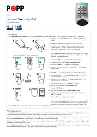
- 1. POPP Universal Z-Wave Key Pad SKU: POPE700045 Quickstart This is a secure Keypad for Europe. To run this device please insert fresh 4 * AAA batteries. Please make sure the internal battery is fully charged. The device can run in two different modes determined by the way its included: Stand-Alone: Include a new device to the keypad using key 1 Network Mode: Be Included into your central controller using key 4 (Central Controller is needed). This is equivalent to activating the ‘Learn‘ mode.The sequence is shown in the image below: Enter Management mode by removing the back-cover (all LEDs will light up) - this will only work in factory default! Here is a quick overview of the commands in management mode: Include Node: MM-> 1 -> * (turns into Stand alone Mode) Exclude Node: MM-> 2 -> * (only in Stand alone Mode) Primary Shift: MM-> 3 -> * (turns into Network Mode) Include (as inclusion or secondary controller): MM-> 4 -> *(turns into Network Mode) Reset: MM-> 5 -> * for 10 seconds (keep * pushed for 10 seconds). Association Set: MM-> 6 -> * -> Group-Number (2,3) -> *, then wait for device NIF for 10 seconds Association Remove: MM-> 7 -> * -> Group-Number (2,3) -> *, then wait for device NIF for 10 seconds New User Code: MM-> 8 -> * -> NUMBER -> * -> PIN -> * Remove User Code: MM-> 9 -> * -> NUMBER -> * Wakeup: hit RING button Send Node Information Frame: Double click Bell button Test the control of an included Door lock (Stand Alone Mode only) : MM-> * -> 0000 -> * Firmware OTA: push ring quickly followed by * After finishing initial setup please set a Master Code (as user code #20) to protect your device. After Master Code (or user code #20) is set the management mode can only be reached by entering the Master Code, regardless if the device is open or closed. You need to reset the device in this case. What is Z-Wave? Z-Wave is the international wireless protocol for communication in the Smart Home. This device is suited for use in the region mentioned in the Quickstart section. (For more information about frequency regulations please refer to the frequency coverage overview at Sigma Designs Website ). Z-Wave ensures a reliable communication by reconfirming every message (two-way communication) and every mains powered node can act as a repeater for other nodes (meshed network) in case the receiver is not in direct wireless range of the transmitter. This device and every other certified Z-Wave device can be used together with any other certified Z-Wave device regardless of brand and origin as long as both are suited for the same frequency range. If a device supports secure communication it will communicate with other devices secure as long as this device provides the same or a higher level of security. Otherwise it will automatically turn into a lower level of security to maintain backward compatibility.
- 2. For more information about Z-Wave technology, devices, white papers etc. please refer to www.z-wave.info. Product Description This keypad is a security enabled Z-Wave Plus product. An security enabled Z-Wave controller must be used to fully utilize this product. The keypad allows securely controlling devices - such as door locks - and trigger actions in a gateway – such as arm/disarm alarm system– based on the entry of certain key codes. Additionally a bell key allows emulating a doorbell by operating e.g. a door bell or a light or both. The device can operate in two different modes. The mode is chosen the way the device is included into a Z- Wave network: 1. Stand Alone Mode. In this case the keypad acts as the primary network controller and will include other devices such as e.g. a strike lock control or a door bell. No other central controller is needed. The management of user codes is done using the keypad itself. 2. Network Mode. The keypad is included as additional device into an exiting network. In Z-Wave terms it will then act as inclusion (secondary) controller. It will send commands to a central controller and is managed by this controller. In this mode the device can still directly control door locks but it can also be used to trigger scenes in a central controller. The device is protected by a tamper switch sending out an alarm message when the enclosure is opened. Prepare for Installation / Reset Please read the user manual before installing the product. In order to include (add) a Z-Wave device to a network it must be in factory default state. Please make sure to reset the device into factory default. You can do this by performing an Exclusion operation as described below in the manual. Every Z-Wave controller is able to perform this operation however it is recommended to use the primary controller of the previous network to make sure the very device is excluded properly from this network. Reset to factory default This device also allows to be reset without any involvement of a Z-Wave controller. This procedure should only be used when the primary controller is inoperable. Open The device, hit button 5 for then keep button * pressed for 10 seconds. The red LED will start flashg the last 5 seconds of the waiting time. Safety Warning for Batteries The product contains batteries. Please remove the batteries when the device is not used. Do not mix batteries of different charging level or different brands. Installation The device can be mounted on all flat walls or can also be simply put on a table. Due to the IP rating of 44 it can be used outside the house e.g. to operate the main door. Unscrew the little screw on the bottom side of the device to open the enclosure. the back side is mounted ot the wall using screws. There is an isolation foam provided for uneven wall backgrounds The image above shows the main functions an buttons of the device. The device has a standard operation mode to ring the bell and to apply key codes to operate a door lock or generate events in the central controller. All setup and management functions however are performed in a management mode. The management mode can be entered in two different ways: When you open the device (remove the backside cover) the management mode is activated if master user code (20) is not present. Otherwise only entering master user code(20) will activate management mode. Entering the key code #20 will enter the management mode even when the tamper switch is closed. In management mode there is a preset user code 0-0-0-0 for test purposes (only active when enclosure opened and no other user codes present). This code is a valid user code resulting in a Door Open Command sent into Association Group 2. The keypad is powered by 4 standard batteries. Two of them always run in parallel therefore the device will work if only two batteries are inserted. However the lifetime will be 50 % only. The device can be powered by a 5V DC external power supply. Between the batteries there is a small connector for the external power supply. It is safe to keep the batteries inserted for fall-back. Inclusion/Exclusion On factory default the device does not belong to any Z-Wave network. The device needs to be added to an existing wireless network to communicate with the devices of this network. This process is called Inclusion. Devices can also be removed from a network. This process is called Exclusion. Both processes are initiated by the primary controller of the Z-Wave network. This controller is turned into exclusion respective inclusion mode. Inclusion and Exclusion is then performed doing a special manual action right on the device. Inclusion Turn into Management Mode, hit button 4 and confirm with * (Star Key) Exclusion Turn into Management Mode, hit button 4 and confirm with * (Star Key) Product Usage The keypad allows typing in up to 20 different key codes and pressing certain dedicated buttons Key codes are numbered 1 20 must have minimum 4 and
- 3. using the "#" key. The bell key will immeditately cause ringing a bell if there is a bell devices included in association group 3. They entry of the key code should be confirmed by "*". If no "*" is entered the entry will time out and use the key entered so far. This means its possible not to confirm by "*" and wait for the timeout of few seconds. Stand Alone Mode
- 4. test of included stike lock The purpose of the stand-alone mode is to use the keypad together with a door lock and a indicator device (Door bell, light switch – to indicate bell ring). The keypad has two control groups (in Z-Wave language association group), one to control a door lock using key codes and one controlling the door bell using the bell key. So simplify the setup process the keypad will automatically place the first included door lock into the control group for door locks (#2) and the first included binary switch into control group for doorbell (#3). The two image sequences below show how to include a door lock (e.g. strike lock) and/or a a switch acting as door chime into a stand alone key pad. Hence to setup the keypad for simple door control, perform the following steps: 1. Open back cover to activate management mode (Step 1+ 2) or activate Management Mode using the Master Key (steps *). 2. Hit button 1 -> "*" and include the door lock (e.g. Popp Strike lock) (Steps 3 + 4 + 5) 3. Check the configuration of correct operation with green on status LED (Steps 6) 4. Enter the test user code *-> 0-0-0-0 (Step 7 and 8) 5. Confirm the entry using * (Step 9) and see the included door lock opening (Step 10). Likewise the bell can be tested as shown in the next image sequence: 1. Open back cover to activate management mode (Step 1+ 2) or activate Management Mode using the Master Key (steps *). 2. Hit button 1 -> "*" and include the door lock (e.g. Popp Strike lock) (Steps 3 + 4 + 5) 3. Check the configuration of correct operation with green on status LED (Steps 6) 4. Hit Bell button (Step 7) and see the associated switch or bell acting (Step 8).
- 5. Test of included bell switch
- 6. It is also possible to manage the keycodes to operate the door lock when being in the management mode. The image sequence shows how to do this. 1. Enter Management Mode either opening the case or entering Master key (Step 1,2) 2. Hit button 8 and confirm with "*" (Enter Key ‘8‘ and confirm with ‘*‘ (step 3,4) 3. Enter the user code slot number 1 ...20. User Codes are always assigned to fixed slot numbers regardless when they where entered or changed. (Step 5) 4. Confirm the slot selection with ‘*‘ (Step 6) 5. Select a user code between 4 and 10 digits and confirm with ‘*‘. (Step7,8) Network Mode The purpose of the network mode is to use the keypad as control device for the whole Smart Home. This means that after including the keypad into the network of the central controller this very controller will receive event notifications for all actions performed on the keypad: Entering a valid key code (Scene ID 20 is issued). Its possible to issue the key code number as scene ID by setting the configuration parameter #5 accordingly Hitting the bell button once: Scene ID 21 Hitting the bell button twice within one second: Scene ID 22 Entering a invalid key code : Scene ID 23 The central controller will see the keypad as a kind of remote control with various buttons (key codes and real buttons). Additionally the tamper switch status is reported to protect the device against tampering. Attention: If you use the keypad as device with Popp-Hub or any other Z-Way based controller you need ot install the app ‘Keypad‘ for managaging user codes accessing the usage history (keycodes entered, failed attempts) Management 1. In network mode the management of user codes can be done both locally on the keypad and using the central controllers Graphical User Interface. In case the central control offers a user interface for door lock management a history of valid and invalid key code entries can be accessed. 2. While in network mode the keypad can also directly control door locks and bells using the association functions built in. Just include the door lock and the switch from your central controller and use the central controllers Z-Wave association management interface to place the lock in association group 2 and the bell switch in association group 3. Its also possible to use the key codes mentioned in the quick start to set and unset these associations. Indications When the device is in standby no LED is on. Turning on management mode or activating the button for further button entry turns the blue LED on. Every recognized button push will turn off the blue background for a moment to confirm successful button press Depending on Configuation Parameter 6 the buzzer will sound to confirm any button press. The status LED indicates:
- 7. Error: red blink for 3,5 seconds Learn Mode: blue/green are blinking constantly Next Menu: blue LED blinks for one second Waiting for user code: blue LED blinks fast Waiting for reset: blue LED blinks very fast Management Mode: green blinking slowly Inclusion/Exclusion: red/green LEDs are blinking constantly Notifications The device sends the following notifications to the central controller using Lifeline: Access Control (0x06): "Manual code exceeds limits (0x13)"; Sent, when pin code entered is more then 10 Access Control (0x06): "Invalid User Code (0x14)";Sent, when entered pin code doesn’t exist Access Control (0x06): "Keypad Unlock (0x06)"; Sent, when entered pin code is correct and door is opened. This command also encapsulates the USER_CODE_REPORT with the pin entered Access Control (0x06): "All User Codes Deleted (0x0c)";Sent, when all pin codes arre removed by command from controller Access Control (0x06): "Single User Code deleted (0x0d)";Sent, when new pin code is removed by command from controller, or manually on the keypad Access Control (0x06): "New User Code added (0x0e)"; Sent, when new pin code is added by command from controller, or manually on the keypad Access Control (0x06): "New User Code not added (0x0f)"; Sent, when after attempt to add new pin code, using keypad Burglar Alarm (0x07): "Tamper Removed"; When keypad is unmounted and enclosure is opened BASIC Command Handling Basic Command Class is not supported and received Basic commands are ignored. Known Problems Association Group2 do not send DoorlockCC: Include the Popp Keypad second time again after door lock Node Information Frame The Node Information Frame (NIF) is the business card of a Z-Wave device. It contains information about the device type and the technical capabilities. The inclusion and exclusion of the device is confirmed by sending out a Node Information Frame. Beside this it may be needed for certain network operations to send out a Node Information Frame. To issue a NIF execute the following action: Hit 0 plus * (Star Key) in Management Mode Communication to a Sleeping device (Wakeup) This device is battery operated and turned into deep sleep state most of the time to save battery life time. Communication with the device is limited. In order to communicate with the device, a static controller C is needed in the network. This controller will maintain a mailbox for the battery operated devices and store commands that can not be received during deep sleep state. Without such a controller, communication may become impossible and/or the battery life time is significantly decreased. This device will wakeup regularly and announce the wakeup state by sending out a so called Wakeup Notification. The controller can then empty the mailbox. Therefore, the device needs to be configured with the desired wakeup interval and the node ID of the controller. If the device was included by a static controller this controller will usually perform all necessary configurations. The wakeup interval is a tradeoff between maximal battery life time and the desired responses of the device. To wakeup the device please perform the following action: hit Ring Key Quick trouble shooting Here are a few hints for network installation if things dont work as expected. 1. Make sure a device is in factory reset state before including. In doubt exclude before include. 2. If inclusion still fails, check if both devices use the same frequency. 3. Remove all dead devices from associations. Otherwise you will see severe delays. 4. Never use sleeping battery devices without a central controller. 5. Dont poll FLIRS devices. 6. Make sure to have enough mains powered device to benefit from the meshing Firmware-Update over the Air This device is capable of receiving a new firmware 'over the air'. The update function needs to be supported by the central controller. Once the controller starts the update process, perform the following action to confirm the firmware update: hit * (Star Key) Association - one device controls an other device Z-Wave devices control other Z-Wave devices. The relationship between one device controlling another device is called association. In order to control a different device, the controlling device needs to maintain a list of devices that will receive controlling commands. These lists are called association groups and they are always related to certain events (e.g. button pressed, sensor triggers, ...). In case the event happens all devices stored in the respective association group will receive the same wireless command wireless command, typically a 'Basic Set' Command. Association Groups:
- 8. Group Number Maximum Nodes Description 1 10 Lifeline 2 10 Door Lock Control 3 10 Ring Button Control Special Operations as Z-Wave Controller As long as this device is not included into a Z-Wave network of a different controller it is able to manage its own Z-Wave network as primary controller. As a primary controller the device can include and exclude other devices in its own network, manage associations, and reorganize the network in case of problems. The following controller functions are supported: Inclusion of other devices Communication between two Z-Wave devices only works if both belong to the same wireless network. Joining a network is called inclusion and is initiated by a controller. The controller needs to be turned into the inclusion mode. Once in this inclusion mode the other device needs to confirm the inclusion - typically by pressing a button. If current primary controller in your network is in special SIS mode this and any other secondary controller can also include and exclude devices. To become primary a contoller have to be resetted and then include a device. Turn into Management Mode, hit button 1 and confirm with * (Star Key) Exclusion of other devices The primary controller can exclude devices from the Z-Wave network. During exclusion the relationship between the device and the network of this controller is terminated. No communication between the device and other devices still in the network can happen after a successful exclusion. The controller needs to be turned into the exclusion mode. Once in this exclusion mode the other device needs to confirm the exclusion - typically by pressing a button. Attention: Removing a device from the network means that it is turned back into factory default status. This process can also exclude devices from it's previous network. Turn into Management Mode, hit button 2 and confirm with * (Star Key) Shift of Primary Controller Role The device can hand over its primary role to another controller and become secondary controller. Turn into Management Mode, hit button 3 and confirm with * (Star Key). To update the network informsation from a primary controller please activate ‘Learn‘ mode. This operation will replicate all network functions and the information about the nwetwork topology from this device to the new primary controller. If yoi want to update the network information in other controllers without handing of the primary function, just reinclude this other controller. Configuration Parameters Z-Wave products are supposed to work out of the box after inclusion, however certain configuration can adapt the function better to user needs or unlock further enhanced features. IMPORTANT: Controllers may only allow configuring signed values. In order to set values in the range 128 ... 255 the value sent in the application shall be the desired value minus 256. For example: To set a parameter to 200 it may be needed to set a value of 200 minus 256 = minus 56. In case of a two byte value the same logic applies: Values greater than 32768 may needed to be given as negative values too. Parameter 1: Door Lock Automatic Secure Timeout After this time a CLOSE command is sent to the controlled door lock. On default no CLOSE command is sent assuming that the strike lock has its own timeout set Size: 1 Byte, Default Value: 3 Setting Description 0 - 127 Seconds Parameter 2: Ring Button Press Basic Command OFF Timeout After this time the Door Bell will receive an OF command regardless of the actuall button is pressed or not Size: 1 Byte, Default Value: 3 Setting Description 3 - 127 Seconds Parameter 3: Ring Button ON Command This value is sent into Association Group 3 when the door bell button is pressed. Size: 1 Byte, Default Value: 255 Setting Description 0 - 99 Basic Set Command Value 255 Basic Set Command Value Parameter 4: Ring Button OFF Command This value is sent into Association Group 3 when the door bell button is released or the timeout has reached. Size: 1 Byte, Default Value: 0 Setting Description 0 - 99 Basic Set Command Value
- 9. Parameter 5: Central Scene ID for User Codes This parameter defines if different user codes shall cause individual or similar scene ID sent to the main controller. Size: 1 Byte, Default Value: 1 Setting Description 0 Constant Scene ID 20 for all User Codes 1 Individual User Codes 1 ... 20 Parameter 6: Buzzer Confirmation Size: 1 Byte, Default Value: 1 Setting Description 0 Disabled 1 Enabled Technical Data Dimensions 120x75x25 mm Weight 230 gr Hardware Platform ZM5101 EAN 4251295700045 IP Class IP 44 Voltage 5V DC Battery Type 4 * AAA Device Type Keypad Generic Device Class Portable Controller Network Operation Portable Controller Firmware Version 01.05 Z-Wave Version 6.51.10 Certification ID ZC10-17085733 Z-Wave Product Id 0115.0100.0103 Supported Command Classes Sensor Binary Association Grp Info Device Reset Locally Central Scene Zwaveplus Info User Code Configuration Alarm Manufacturer Specific Powerlevel Firmware Update Md Battery Wake Up Association Version Security
- 10. Controlled Command Classes Basic Door Lock Explanation of Z-Wave specific terms Controller — is a Z-Wave device with capabilities to manage the network. Controllers are typically Gateways,Remote Controls or battery operated wall controllers. Slave — is a Z-Wave device without capabilities to manage the network. Slaves can be sensors, actuators and even remote controls. Primary Controller — is the central organizer of the network. It must be a controller. There can be only one primary controller in a Z-Wave network. Inclusion — is the process of adding new Z-Wave devices into a network. Exclusion — is the process of removing Z-Wave devices from the network. Association — is a control relationship between a controlling device and a controlled device. Wakeup Notification — is a special wireless message issued by a Z-Wave device to announces that is able to communicate. Node Information Frame — is a special wireless message issued by a Z-Wave device to announce its capabilities and functions. (c) 2018 Z-Wave Europe GmbH, Antonstr. 3, 09337 Hohenstein-Ernstthal, Germany, All rights reserved, www.zwave.eu. The template is maintained by Z-Wave Europe GmbH. The product content is maintained by Z-Wave Europe GmbH , Supportteam, support@zwave.eu. Last update of the product data: 2017-11-10 11:38:57