

Recommended
Recommended
More Related Content
What's hot
What's hot (20)
Similar to 2301 manual (v7.0 - 80384 a) (1) gefran
Similar to 2301 manual (v7.0 - 80384 a) (1) gefran (20)
Recently uploaded
Recently uploaded (20)
2301 manual (v7.0 - 80384 a) (1) gefran
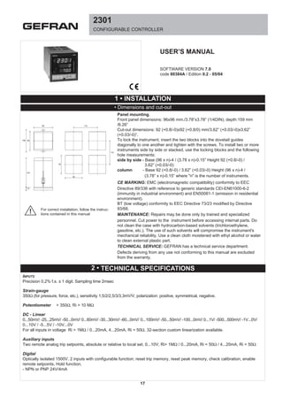
- 1. 2301 CONFIGURABLE CONTROLLER SOFTWARE VERSION 7.0 code 80384A / Edition 0.2 - 05/04 USER’S MANUAL 96 115 108 96 157 10 92 92 115 1 • INSTALLATION • Dimensions and cut-out For correct installation, follow the instruc- tions contained in this manual! Panel mounting. Front panel dimensions: 96x96 mm./3.78”x3.78” (1/4DIN); depth:159 mm /6.26” Cut-out dimensions: 92 (+0.8/-0)x92 (+0.8/0) mm/3.62” (+0.03/-0)x3.62” (+0.03/-0)”. To lock the instrument, insert the two blocks into the dovetail guides diagonally to one another and tighten with the screws. To install two or more instruments side by side or stacked, use the locking blocks and the following hole measurements: side by side - Base (96 x n)-4 / (3.78 x n)-0.15” Height 92 (+0.8/-0) / 3.62” (+0.03/-0) column - Base 92 (+0.8/-0) / 3.62” (+0.03/-0) Height (96 x n)-4 / (3.78” x n)-0.15” where "n" is the number of instruments. CE MARKING: EMC (electromagnetic compatibility) conformity to EEC Directive 89/336 with reference to generic standards CEI-EN61000-6-2 (immunity in industrial environment) and EN50081-1 (emission in residential environment). BT (low voltage) conformity to EEC Directive 73/23 modified by Directive 93/68. MAINTENANCE: Repairs may be done only by trained and specialized personnel. Cut power to the instrument before accessing internal parts. Do not clean the case with hydrocarbon-based solvents (trichloroethylene, gasoline, etc.). The use of such solvents will compromise the instrument's mechanical reliability. Use a clean cloth moistened with ethyl alcohol or water to clean external plastic part. TECHNICAL SERVICE: GEFRAN has a technical service department. Defects deriving from any use not conforming to this manual are excluded from the warranty. 2 • TECHNICAL SPECIFICATIONS INPUTS Precision 0,2% f.s. ± 1 digit. Sampling time 2msec Strain-gauge 350Ω (for pressure, force, etc.), sensitivity 1,5/2/2,5/3/3,3mV/V, polarization: positive, symmetrical, negative. Potentiometer > 350Ω, Ri > 10 MΩ DC - Linear 0...50mV/ -25...25mV/ -50...0mV/ 0...60mV/ -30...30mV/ -60...0mV/ 0...100mV/ -50...50mV/ -100...0mV/ 0...1V/ -500...500mV/ -1V...0V/ 0...10V / -5...5V / -10V...0V For all inputs in voltage Ri > 1MΩ / 0...20mA, 4...20mA, Ri = 50Ω. 32-section custom linearization available. Auxiliary inputs Two remote analog trip setpoints, absolute or relative to local set. 0...10V, Ri> 1MΩ / 0...20mA, Ri = 50Ω / 4...20mA, Ri = 50Ω Digital Optically isolated 1500V. 2 inputs with configurable function: reset trip memory, reset peak memory, check calibration, enable remote setpoints, Hold function. - NPN or PNP 24V/4mA 17
- 2. 18 2 • TECHNICAL SPECIFICATIONS OUTPUTS Continuous MAIN analog control in voltage or DC 1500V isolation 0...10Vdc, -5...5Vdc, -10...10Vdc Rload > 500Ω short-circuit protection 0...20mA, 4...20mA, Rmax = 500Ω Relay With 5A/250Vac contacts at cosϕ = 1 (3,5A at cosϕ = 0,4). Spark suppression on NO contacts. Logic In voltage for static relay control (SSR) 23Vdc, Rout = 470Ω (20mA, max. 12V). Retransmission 1500V isolation. Retransmission output for input, peak values, remote sets, direct and inverse control output, positive or negative deviation, alarm setpoint, configurable scale (minimum and maximum) settable from panel keys. 0..10Vdc; Rload > 500Ω / 0...20mA, 4...20mA Rmax = 500Ω Resolution 4000 points. Response time 8 msec. SERIAL LINE Optically isolated 4 wires. The instrument is available with Current Loop (1200 baud) or RS485 4-wire (1200...9600 baud). Protocol: GEFRAN CENCAL or MODBUS SENSOR SUPPLY 1500V isolation. 5, 10 or 15Vdc...200mA or 24Vdc...100mA POWER SUPPLY 100...240Vac ±10% / 11...27Vac/dc ±10% / 50...60Hz; 15VA max. Protected by internal fuse not serviceable by user AMBIENT CONDITIONS Working temperature: 0...50°C Temperatura di stoccaggio: -20...70°C Storage temperature: 20...85%Ur non-condensing CONTROLLER Self-adaptive PI or PID control with calculation time every 20 msec. ìAutomatic/manual function with bumpless function to prevent disturbance on return to auto mode after period of manual process control. Auto or manual status programmable at power-on. Ramp can be set for switch from current setpoint to new setpoint. Gradient can be defined for power update (calculated from control algorithm). Digital filter programmable on input signal; digital filter programmable on process variable display. Saving of max peak, min peak, max-min peak value of input signal retrievable by means of panel button and LED signal. ALARMS - 2 alarm setpoints settable in absolute or deviation value with functions completely configurable from panel keys (Direct / Reverse / Deviation / Symmetrical Deviation) - Setting of trip point along entire selected scale. - Trip hysteresis settable from panel keys. - Function: minimum or maximum trip points with saving of trip (LATCH) selectable during configuration. Assigned to process variable or to setpoint. Relays energized or de-energized in trip status: selected from panel keys. Trip can be excluded during power-up phase until input variable exceeds set trip point. Relay trips when variable drops below trip point. Output activation can be timed. ìTrip response time: for AL1 and AL2 = 2 msec WEIGHT 700g
- 3. 19 3 • DESCRIPTION OF FACEPLATE A Display * Value of controlled variable resolution 4000 points in range - 1999/+9999, selectable decimal point, off-scale (-HI-) or (Lo) signal; indication of broken Strain Gauge probe: E_br: probe energizing interrupted H.sbr: wire + interrupted L.sbr: wire - interrupted B Display Displays settings, setpoint, trip points, remote setpoints. Data is presented as messages on display C or as status of LEDs M. Under normal work conditions, displays selected setpoint (local or remote). C Display Displays messages during configuration and power level 0/100.0%. Power is displayed during normal operation, and can be changed with keys or by remote input in manual mode (MAN LED flashing). D Display Bargraph 0/100%. Graphic display of power as percentage. N Display Bargraph ± 10%. Graphic display of deviation value as percentage. M Display Signal LEDs: MAN MAN indicates Manual controller state. When flashing, indicates that power may be varied with Raise and Lower keys. REM signals that remote setpoint (absolute or deviation) is on. CAL signals calibration control by probes or transmitters. AL1/AL2 flashing signals indicating display of trip points. If on, indicates that relay is energized. CONTROLS E “F” Function button Accesses value display and/or setting functions. If button F is not pushed to confirm a setpoint change, it will be saved automatically after 10 seconds. Use button F to confirm the set value. Keep button F pressed to access the various configuration and calibration phases. By simultaneously pressing key F and the Raise and Lower buttons, you can enter the calibration menu even with protection S4 OFF. F / G Raise and Lower Buttons Let you increase or decrease displayed value for setting data or selecting an option. During calibration of repetition output or control output, the Raise/Lower keys let you change the minimum and maximum value. Increase/decrease speed is proportional to the time the key is kept pressed. The procedure is not cyclical: when the maximum (minimum) for the field is reached, the function stops even if the key is pressed. During manual function, the keys let you change the power level. H "MAN/AUTO" button Configurable function (see CFG2 butt.3 parameter): - automatic calibration control for pressure probes or transmitters (♦) - reset trip memory - reset peak memory (♦♦) - enable remote set 1 and/or 2 - select Manual/Automatic - HOLD function for sampled input value I "CAL/RST" button Configurable function (see CFG2 butt.2 parameter): - automatic calibration control for pressure probes or transmitters (♦) - reset trip memory - reset peak memory (♦♦) - enable remote set 1 and/or 2 - select Manual/Automatic - HOLD function for sampled input value L "PEAK" button Pressing the Peak button displays the peak value, i.e., the data shown on display B corresponds (depending on the type of peak selected) to (see CGF2 butt.1 parameter): - "peak +" maximum value reached by variable - "peak -" minimum value reached by variable - "peak - peak" difference between "peak +" and "peak -" Press key F to exit. The instrument resumes display of the process variable. Peak memory remains active internally, and can be displayed at any time. (♦)The calibration control function provides a known calibration signal from the unstressed transducer. In this condition, alarm relay status and the value of the analog input repetition signal are unchanged. The calibration function is signaled by lighting of the LED on the front panel (CAL). (♦♦) When the peak memory reset function is enabled, the button updates the peak memory to the current value of the input signal. These functions are also available by means of configurable external contacts (see "Electrical connections" and "Configuration CFG2: d.i.F.1 and d.i.F.2). C D M FG EIL H A B N
- 4. 20 To remove the electronic part of the case, turn the front screw until release, then remove manually. (Attention: high voltage due to residual loads on condensers). Configure by making jumpers on electronic boards of instrument. Configuration notes Access to configuration and calibration depends on the position of jumpers on CPU board: Jumper J3 ON (closed) = enable configuration. Jumper S4 ON (closed) = enable calibration. (jumper S4 on solder side of CPU board) 6 • HARDWARE CONFIGURATION The instrument consists of 2 basic boards and has 44 terminals divided into 2 section (A and B). Signal inputs Signal inputs from pressure probes and signals in direct voltage and in direct current 0-20mA, 4-20mA use terminals A1 (+) and A2 (-). For the potentiometer input, the max end must be connected to terminal B20 (+Exc), the min end to terminals A2 and A3 (-), the cursor to terminal A1 (+). Remote setpoint inputs GThe 0-10V, 0-20mA, 4-20mA inputs for any remote set points use terminals A15 (+), A14 (-) for set 1 and A13 (+), A12 (-) for set 2. Digital inputs NPN isolated digital inputs (from switch, relay, open collector) or PNP 4mA use terminals A6 (IN1), A7 (IN2) and A4 (GND). Calibration output For input from pressure probe, terminals B21, B22 are available for calibration contacts. Probe power output Power for pressure probes, potentiometers, transmitters, available on terminals B20 (+Exc) and A3 (-Exc). Available voltages are: 5V/200mA, 10V/200mA, 15V/200mA, 24V/100mA (see hardware configuration). Any shielding on the probe connection cable must be connected to terminal A3 (-Exc). Repetition output W Available at terminals A5 (+) and A4 (-) with output in voltage 0-10V or 0-20mA or 4-20mA isolated. Minimum and maximum can be corrected from panel keys (see calibration of repetition output). Power supply for potentiometer 10V (20mA max) voltage is available at terminal A16 (+VP) to power a potentiometer used to set a remote setpoint. MAIN control output Available at terminals A22 (+) and A21 (-), standard 0-10V, 0- 20mA, 4-20mA. Minimum and maximum can be corrected from panel keys (see calibration of control output). Digital communication - Type C.L. interface: reception diode available at terminals A10 (+Rx) and A11 (-Rx), transmission transistor at terminals A8 (+Tx) and A9 (-Tx). Resistance in series to diode is 1KΩ, in series to transistor collector 100Ω. For connection in series, diode resistance is reduced to 100Ω (see hardware configuration). - Type RS485 4 wire interface (RS422 compatible):A11, A9 like A (data +) and A10, A8 like B (data -). The transmission distance covered by the RS422/RS485 serial output reaches 500 meters with a maximum of 32 instruments connected. For line lengths greater than 50 meters, and when a line termination impedance is required, solder jumpers X, Y, and Z on the Solder Side of board 45028.1 (see appendix). Make the termination on the instrument farthest away on the serial connection chain. OUT1 alarm output Relay output on terminals B16 (c), B15 (n.o.) and B14 (n.c.); contact capacity is 5A / 220V; isolated logic output (*) type D2 24V/20mA max on terminals B16 (+) and B15 (-). OUT2 alarm output Relay output on terminals B17 (n.c.), B18 (c) and B19 (n.o.); contact capacity is 5A/220V; isolated logic output (*)type D2 24V/20mA max on terminals 19 (+) and 18 (-). (*) not isolation with respect to probe supply. Equivalent scheme for D2 logic type output Instrument power supply Power supply of 90/260Vac, 10/30Vdc/ac is applied to terminals B12 and B13. 5 • ELECTRICAL CONNECTIONS 4 • CONNECTIONS See the Appendix to the manual for the electrical diagrams.
- 5. Digital input configuration Based on the input required, position the jumpers as follows: (♣) Jumpers are on CPU board, components side. (*) Standard configuration Configuration of repetition output W Based on the output required, position the jumpers as follows: Configuration of MAIN control output Based on the output required, position the jumpers as follows: (see main-out board) During the power-on phase, the control output goes to mini- mum value (the MAIN ±5V output goes to -5V, ±10V to -10V). Configuration of C.L. (current loop) serial interface Set the jumpers as per the table based on the type of connec- tion you want: Jumpers S5, S6 are on CPU board, solder side. (♣) Jumpers are on CPU board, components side. (*) Standard configuration Power configuration for probe, transmitter or potentiometer Based on the voltage level required, position the jumpers as follows: Jumpers J5-J1-J15-J24 are on the components side of the power board Probe input configuration For inputs 0-1V, 0-10V, 0-20mA, 4-20mA and potentiometer, position jumpers S3A, S3B, S3C and SI as follows: Configuration from panel keys is also necessary for all types of inputs (CGF.3, in.typ and In.cod parameters). Input configuration for remote setpoints Based on the input required, position the jumpers as follows: J5 J10 J15 J24 5V / 200mA ON OFF OFF OFF 10V / 200mA(*) OFF ON OFF OFF 15V / 200mA OFF OFF ON OFF 24V / 100mA OFF OFF OFF ON 21 J1P J1N J2P J2N Input 1:NPN (*) OFF ON voltage-free contact - open collector 24V/4mA Input 1:PNP (24V/4mA) ON OFF Input 2:NPN (*) OFF ON voltage-free contact - open collector 24V/4mA Input 2:PNP (24V/4mA) ON OFF DIGITAL INPUT TYPE JUMPERS (♣) INPUT TYPE JUMPERS (♣) S3A S3B S3C SI 0 - 1V ON ON OFF OFF 0 - 10V e OFF OFF OFF OFF Transmitter 10V Potenziometer OFF OFF OFF OFF 0-20mA / 4-20mA and ON ON OFF ON Transmitter 20mA Strain gauge, 0-50mV, OFF OFF ON OFF 0-60mV, 0-100mV (*) S1A S1B S2A S2B Remote set 1 / 0-10V (*) OFF OFF Remote set 1/0-20mA/4-20mA ON ON Remote set 2 / 0-10V (*) OFF OFF Remote set 2/0-20mA/4-20mA ON ON REMOTESETPOINTINPUTTYPE JUMPERS (♣) REPETITION OUTPUT TYPE JUMPERS (♣) J5V J5I J6 0-10V o 2-10V ON OFF ON 0-20mA o 4-20mA (*) OFF ON OFF J3 J4 J5 JS1 JS2 JS3 0-10V or 2-10V (*) ON ON V OFF ON OFF ±5V ON ON V ON OFF OFF ±10V ON OFF V OFF OFF ON 0-20mA or 4-20mA OFF ON I OFF ON OFF MAIN OUTPUT TYPE JUMPERS POWER LEVEL JUMPER 6 • HARDWARE CONFIGURATION See the Appendix to the manual for the drawings of the Power, CPU, and MAIN Output boards TYPE OF CONNECTION JUMPERS S5 S6 Jumper (*) OFF ON Series ON OFF
- 6. InFo Access the display by keeping the F key pressed. The InFo message will appear on the display after a few seconds. Release the F key to enter the information display phase: - Press the F key: the display will show the message CodE with the set serial communication code value; - Press the F key: the display will show the message UPdt with the number of the software release used on the instrument; - Press the F key: the display will show the message Prot with the set software protection level; - Press the F key: you will return to the variable display. 7 • SOFTWARE CONFIGURATION 9 • PARAMETERS SETTING During normal operation, press the F key and release it when the display shows the message dAtA Parameters to be set if control is PID (Ctr.t = 0). _Pb: proportional band in range 0.1/800.0%. _it: integral time in range 00.0/99.9 sec. (by setting 0.0 the integral action is excluded). A weak integral action corresponds to a high integral time, while a strong integral action corresponds to a low integral time. _dt: derivative time in range 0.0/99.9 sec. (by setting 0.0 the derivative action is excluded). The effectiveness of the derivative action increases in proportion to the derivative time _rSt: manual reset in range -99/+99 scale points algebraically added to the setpoint value. After the control has settled, bring the value of the controlled variable exactly to the set setpoint (at times this is necessary in PD controls). PrSt: reset power in range -100.0%/+100.0%. This contribution is added to the power calculated by the PID control. ArSt: integral or antireset range, 0/9999 scale points (outside this range there is no updating of the integral power component); set 0 to exclude the action. Atun: type of autotuning: 0 = action disabled; 1 = continuous; 2 = One Shot enabled; 3 = One Shot activated. Per ulteriori informazioni vedere le note di funzionamento. _FFd: feed forward in range 0/100.0% or predictive action: coefficient of proportionality that multiplies the percentage value of the setpoint referred to the scale range (feedforward power = FFd * SP%). This contribution is added to the power calculated by the control Parameter to be set if the control type (Ctr.t = 1) is self-adaptive. _S.t_: delay time in range 0.1 - 100.0 sec.; corresponds to process speed; useful for compensating for system delay time. Introduction to setting, configuration and calibration procedures: The various steps are accessed by means of button F. Changes are made with the Raise and Lower keys. Main menu Normal operation is characterized by: - Process variable on display A - Active setpoint on display B - Control output in percentage on display C The REM LED on indicates that the remote setpoint is active. The MAN LED flashing indicates setting of local control power value with the raise or lower key. If no keys are pressed during data display on the main menu, timed return to normal functioning is activated. Press key F for a few seconds to access configuration steps. The following parameters are selected sequentially by means of key F (function). Displaying and setting local Setpoint Access the setpoint display; you can import it if the protection level permits. Set the setpoint with the raise/lower keys within the maximum and minimum limits defined during configuration (CFG3/LO.SP/HI.SP). Press F to confirm the parameter value and go to the next step. Displaying remote inputs (SET1 REM, SET2 REM) Remote inputs such as setpoint S.P.r.1 and/or S.P.r.2 are displayed in engineering value only if they are enabled as type 1…6 (CFG/tYP.1/tYP.2). Remote inputs such as percentage value Pot1 and/or Pot2 are displayed only if they are enabled as type 7…18 (CFG/tYP.1/tYP.2). Press F to go to the next step. Displaying ratio factor The ratio factor is displayed only if the control has been defined as type 2 or 3, i.e., as ratio (CFG0/Ctr.t). It can be set in the range 0.00…99.99 if the protection level permits. The setting is subject to the same protection level as the setpoint. The value of r.t. = value of main input / value of enabled remote setpoint input (type 1 or 2 or 3) can be set or determined automatically at the time of manual- automatic switching if configuration parameter M.A.ty = 0. Press F to confirm the parameter value and go to the next step (see function notes). Displaying and setting trip points Access the trip point display; it can be set if the protection level permits. During this step, the AL1 or AL2 LED will flash. Set with the raise/lower keys: if absolute, within the scale limits of the main input (CFG3/L.Lin/H.Lin); if reactive, within the range -1000…+1000. Press F to confirm the parameter value and return to normal operation. 22 8 • INFORMATION DISPLAY
- 7. Introduction Configuration is performed in 5 steps: 0) CFG0: Control parameters, control output 1) CFG1: Machine code and Trip Point Hysteresis 2) CFG2: Protection level, I/O function, Serial 3) CFG3: Type of main inputs, remotes and retransmission output 4) CFG4: Linearization table Access these steps by keeping the F key pressed until the message _CFG appears and alternates with the value 0. Use the Raise and Lower keys to set the number of the configura- tion step that you want to access (value 0-4). Then press the F key to go directly to the step selected. Press the F key to scroll the functions/parameters. Access to the various configuration steps is subject to software protection (CFG.0/CFG.1) and hardware protection (CFG.2/CFG.3/CFG.4) according to the following table: If there is protection, you will leave the configuration step and the display returns variable display. Configuration 0 (CFG.0) _P.Lo: Minimum power limit settable in range 0.0-100.0% (±100.0% if Out.C = 4 or 5) considered only in automatic. _P.Hi: Maximum power limit settable in range 0-100% (±100% if Out.C = 4 o 5) considered only in automatic. Out.G: Maximum power gradient settable in range 0.1-99,9%/sec. Set 0 to exclude the limit. Not active in manual control S.P.Gr: Setpoint gradient settable in range 0.1-99.9 digit/sec. with LrTy=1. By setting 0, switching between setpoints is immediate. Ctr.t: Type of control: 0 = PID control 1 = PI self-adaptive control; 2 = PID ratio control 3 = PI self-adaptive ratio control. M.A.ty: Type of switching mode from Manual to Automatic: 0 = Setpoint value is set equal to that of variable and does not cause power variation in switching (for PID control, integral time it must be other than 0). 1 = Setpoint remains unchanged: instrument starts control to reach setpoint (local or remote). A.M.ty: Type of switching mode from Automatic to Manual: 0 = absolute: power value is immediately brought to minimum value. Manual remote returns active if brought to values less than or equal to minimum 1 = deviation: power value does not change, maintains value it had in automatic. Can be increased or decreased with Raise/Lower keys (if in local manual) or by changing input enabled for manual remote (if in local manual). 2 = absolute, setpoint remains unchanged. Control output assumes percentage value of remote input enabled as manual remote. If manual remote selection is not active, behavior is similar to type 1. 3 = deviation, power does not change, maintains the value it had in automatic, forcing digital remote power to the same value. The digital remote power value can be freely raised or lowered with the remote Raise and Lower keys (motopotentiometer simulation function). Mode 3 is enabled only for digital remote manual (motopotentiometer; tYP1 = 39 p tyP.2 = 39) and with positive control output: 0/2 - 10V, or 0/4- 20mA. L.r.ty: Type of switching mode between local setpoint and remote setpoint: 0 = immediate switching from Local to Remote; 1 = switching with set gradient S.P.Gr; from SPLOC to SPr 2 = on the remote to local switch, the local setpoint value assumes the remote setpoint value; 3 = on the local to remote switch, the setpoint variation gradient S.P.Gr; on the remote to local switch, the local setpoint value assumes the remote setpoint value; +4 = to inhibit writing on EEPROM of local setpoint transmitted via serial. P.On.t Type of Power on, conditions set at power-on: 0 = automatic function with local setpoint 1 = manual function with local control; control output at minimum value; 2 = automatic function with remote setpoint, provided that TYOP or 2 is configuredi; 3 = manual function with remote control; control output at minimum value, provided that TYP1 or TYP2 is configured; (if A.M.ty = 2 control output assumes value of remote input). 4 = function at last-saved state (state set by digital input IN1 or IN2 takes priority). Out.C type of MAIN output control CFG.0 Prot= 0/1 (software protection level settable in CFG.2) CFG.1 Prot= 0 (software protection level settable in CFG.2) CFG.2 Jumper J3 closed CFG.3 Jumper J3 closed CFG.4 Jumper J3 closed Jumper J3 on CPU board component side STEP CONDITION FOR ENABLING 0 (*) 0-10V or 0-20mA direct 1 0-10V or 0-20mA indirect 2 2-10V or 4-20mA direct 3 2-10V or 4-20mA indirect 4 ±10 (±5) direct** 5 ±10 (±5) indirect** * Standard configuration ** See power limit settings P.Lo - P.Hi Out.C OUTPUT TYPE 23 9 • PARAMETERS SETTING
- 8. Configuration 1 (CFG.1) CodE Instrument code in range 0/9999 HYS1 Hysteresis for OUT1 in range -1000/+1000. HYS2 Hysteresis for OUT2 in range -1000/+1000. A negative (or positive) number indicates a hysteresis range positioned under (or over) the selected limit, and is typical of a direct (or inverse) trip point. If the output function considers the trip delay instead of hysteresis, the setting is in the range 0/9999 msec. (resolution 2msec. for OUT1 and OUT2). Configuration 2 (CFG.2) Use the F key to confirm set values and go to setting of the next parameter. Prot Software protection level according to table: bAud: Serial communication transmission speed, according to table Sr.P Serial interface protocol 0 CENCAL GEFRAN 1 MODBUS bAu Baudrate bAu Baudrate Interface 0 1200 CL / 485 / 232 1 2400 485 / 232 2 4800 485 / 232 3 9600 485 / 232 4 19200 485 / 232 PAr Parity PAr Parity 0 No parity 1 Odd 2 Even but.1 PEAK key function 0 no function (key not active) 1 activate "peak +" (maximum) (*) 2 activate "peak -" (minimum) 3 activate "peak-peak" (max. peak - min. peak) but.2 CAL/RST key function 0 no function (key not active) 1 reset trip memory 2 reset peak memory 3 reset trip memory + reset peak memory (*) 4 enable/disable remote set (•) 5 select Manual local/Automatic 6 select Manual remote/Automatic (••) 7 calibration control (only for strain gauge 6-wire type probes) but.3 MAN/AUTO key function 0 no function (key not active) 1 reset trip memory 2 reset peak memory 3 reset trip memory + reset peak memory 4 enable/disable remote set (•) 5 select Manual local/Automatic (*) 6 select Manual remote/Automatic (••) 7 calibration control (only for strain gauge 6-wire type probes) d.i.F.1 digital input 1 function 0 no function (key not active) (*) 1 reset trip memory 2 reset peak memory 3 reset trip memory + reset peak memory 4 enable remote set (•) 5 select Manual local 6 select Manual remote (••) 7 calibration control (only for strain gauge 6-wire type probes) 8 HOLD sampled input value function: (sampled input value, trip points, control are "frozen" for the time the input is active). 9 control probe supply. Digital input 1 (IN1) used to determine probe supply control must be type PNP polarized (see configuration of digital inputs). The digital input has to be connected in parallel to the probe supply. Connect terminals 4 to -Exc, terminals 6 (diF1) to +Exc. If power fails to the probe, the display shows e.br; the outputs go to configuration state (rEL). 10 Power-off function (see function notes) d.i.F.2 digital input 2 function 0 no function (key not active) (*) 1 reset trip memory 2 reset peak memory 3 reset trip memory + reset peak memory 4 enable remote set (•) 5 select Manual local 6 select Manual remote (••) 7 calibration control (only for strain gauge 6-wire type probes) 8 HOLD sampled input value function: (sampled input value, trip points, control are "frozen" for the time the input is active). 24 9 • PARAMETERS SETTING 0 - read input - setpoint - setpoint - trip points - trip points - Step “CFG.0/1” - Step “INFO” - Step “dAtA” - Step “dAtA” - Step “CFG.0/1” 1 - read input - setpoint - setpoint - trip points - trip points - Step “dAtA” - Step “INFO” - Step “CFG.0” - Step “dAtA” - Step “CFG.0” 2 - read input - setpoint - setpoint - trip points - trip points - Step “dAtA” - Step “INFO” - Step “dAtA” 3 - read input - setpoint - setpoint - trip points - trip points - Step “INFO” 4 - read input - setpoint - setpoint - trip points 5 - read input - setpoint 8 To disable access to calibration (*) Standard protection level is 2. Remember that Jumper J3 = ON enables access to CFG2, CFG3, CFG4. “Prot” DISPLAY CHANGE
- 9. 9 • PARAMETERS SETTING 9 control probe supply. Digital input 2 (IN2) used to determine probe supply control must be type PNP polarized (see configuration of digital inputs). The digital input has to be connected in parallel to the probe supply. Connect terminals 4 to -Exc, terminals 6 (diF1) to +Exc. If power fails to the probe, the display shows e.br; the outputs go to configuration state (rEL). 10 Power-off function (see function notes) (•) Rem. set enabled: REM LED on if tYPr1 and/or tYPr2 also enabled in CFG3. (••) Value of main output is controlled by remote if remote inputs are configured (TyP.1 and TyP.2) for remote manual N.B. IN1 and IN2 are set as diF1 = 5 and diF2 = 6, the second has priority. out.1 output 1 function (see trip point function) 0 direct absolute (direct function same as having an energized relay for values above set trip point). (*) 1 inverse absolute (inverse function same as having an energized relay for values below set trip point). 2 direct deviation referred to setpoint 3 inverse deviation referred to setpoint 4 direct symmetrical deviation (window) referred to setpoint. Relay energized outside 5 inverse symmetrical deviation (window) referred to setpoint. +8 inverse symmetrical deviation (window) referred to setpoint until the first alarm (functions only in case of inverse alarm). +16 to code selected for trip point with memory. +32 to code selected for probe interrupt or power failure alarm (in this case, use DIGITAL INPUT 1 configured d.i.F.1= 9). Relay state depends on parameter rEL. The output functions normally when the probe is not interrupted. +64 to code selected timed trip point delay (in this case, hysteresis is set in msec. and becomes the delay time in activation of output compared to time of tripping). +128 assigned to setpoint value only for absolute trip point. out.2 output 2 function See out.1 _rEL behavior of trip relays in case of broken probe (energizing and/or signal); setting according to following table: Configuration 3 (CFG.3). Use the F key to confirm set values and go to setting of next parameter. I.t.YP type of input e polarization: (•) In this case, set the custom linearization table to 32 segments (see CFG.4). (••) For symmetrical linear inputs, the signal range is divided; for example, if I.t.YO = 5 and I.Cod = 2, the signal may be +/- 50mV. (*) Standard configuration CUSTOM linearization does not permit symmetrical polarization. BREAK+ BREAK- EXCIT± 0(*) OFF OFF OFF 1 OFF OFF ON 2 OFF ON OFF 3 OFF ON ON 4 ON OFF OFF 5 ON OFF ON 6 ON ON OFF 7 ON ON ON Code rEL Behavior of relay in case of: 0(*) POSITIVE (ex. 0...10mV) 1 SYMMETRICAL (ex. -5...5mV) 2 NEGATIVE (ex. 0...10mV) 4 POSITIVE (ex. 0...10mV) 5 SYMMETRICAL (ex. -5...5mV) 6 NEGATIVE (ex. 0...10mV) +8 Custom Linearization (*) +16 To select the input filter in tenths of a second (see Filt parameter) Code rEL Behavior of relay in case of: Strain gauge (Pressure, force, etc.) Linear (V, I, Pot.) 25
- 10. I.Cod sensitivity identification code at input . FiLt constant programming of digital filter time, settable in range 0.0...20.0 sec. (resolution 0.01 sec.) or 0.0...20.0 sec (resolution 0.01 sec.) see I.tYP parameter. It is advisable to turn on the filter at the limit of the admitted trip time. Set = 0 to turn off filter. Fild constant programming of digital filter time on display. Value settable in range 0…9.9 sec. Set -0 to turn off filter. Does not affect trip time. dEC.P position of decimal point or number of decimal digits in range 0/1/2/3. oFSt offset of input in range -1000/+1000 in scale units. L.Lin Minimum linear scale value for input in range -1999/+9999. For symmetrical signals, corresponds to zero value; i.e., if you want an indication of ±1000, L.Lin equals 0. H.Lin Maximum linear scale value for input in range -1999/+9999 (value must be > Lo.Lin). tYP.1 type of signal and assigned function for remote input 1 (see configuration table: tYP.2 type of signal and assigned function for remote input 2 (see configuration table: In case of selection tYP1 = tYP2, tYP1 is considered active for the same type of function. Lo.SP lower limit for setpoints (locals or remotes in scale range -1999/+9999) (may be higher than Hi.SP). Hi.SP upper limit for setpoints (locals or remotes in scale range 1999/+9999 (may be lower than Lo.SP). In case of deviation remote setpoint, setting range for local set is the same as the scale limits of the variable (L.Lin e H.Lin). out.t type of signal in output W (retransmission of input signal) according to table: 0 1,5mV/V Ecc = 5V 0 0-50mV 1 2 1 0-60mV 2 2.5 2 0-100mV 3 3 3 0-1V 4 3.3 4 0-10V 5 1,5mV/V Ecc = 10V 5 0-20mA 6 2 6 4-20mA 7(*) 2.5 7 Potentiometer: 8 3 >350Ω 9 3.3 Power: 10V 10 1,5mV/V Ecc = 15V 11 2 12 2.5 Control “Probe Input” 13 3 configuration 14 3.3 as well. 15(*) Trasmitter 0-10V 16(*) Trasmitter 0-20mA (*Standard Config.) 17(*) Trasmitter 4-20mA (*) Codes 15, 16, 17 permit only positive polarization In.tYP = 0 Codes 6 and 7 (linear) permit only positive polarization: In.tYP = 4 Note: for input 4…20mA, current below 2mA generates message L.Sbr and associated relay state specified with parameter _rEL. STRAIN GAUGE LINEAR In.Cod Sensitivity In.Cod Sensitivity 0(*) Remote input not enabled 1(**) Remote absolute set 0-10V 2 Remote absolute set 0-20mA 3 Remote absolute set 4-20mA 4 Remote relative set 0-10V 5 Remote relative set 0-20mA 6 Remote relative set 4-20mA 7 Manual remote 0-10V 8 Manual remote 0-20mA 9 Manual remote 4-20mA 10*** Reference for control output 0-10V 11*** Reference for control output 0-20mA 12*** Reference for control output 4-20mA 13 Limitation of minimum for control output 0-10V 14 Limitation of minimum for control output 0-20mA 15 Limitation of minimum for control output 4-20mA 16 Limitation of maximum for control output 0-10V 17 Limitation of maximum for control output 0-20mA 18 Limitation of maximum for control output 4-20mA + 32 for motopotentiometer function (requires remote input, which powers the remote buttons, configured to 0-10V) *Standard configuration for tYP.2 **Standard configuration for tYP.1 *** Reference for control output: adds control power to remote input value. tYP.1/.2 CONFIGURATION OF REMOTE INPUTS 0(*) Input (displayed value) 0-10V or 0-20mA 1 Peak + (maximum) 2 Peak - (minimum) 3 Peak - peak 4 Trip point 1 5 Trip point 2 6 Direct main output 7 Inverse main output 8 Deviation (setpoint - input) 9 Deviation (input - setpoint) 10 Setpoint 11 Remote input 1 12 Remote input 2 Note: Add +16 to code 0-12 to obtain output type 2-10V or 4-20mA RETRANSMITTED VARIABLE SIGNAL TYPE 26 9 • PARAMETERS SETTING
- 11. Lo.tr start scale limit for retransmission output in range - 1999/9999. Hi.tr full scale limit for retransmission output in range - 1999/9999. (Lo.tr may be higher than Hi.tr). Limits Lo.tr and Hi.tr are not considered in case of out.t = 6,7 in which a 0-100% scale is forced 0-100% (±100% if Out.t = 11,12 if tYP.1 or tYP.2 > 6. Configuration 4 (CFG.4). Setting custom linearization table in 32 segments. ATTENTION: before setting, you must know the various corre- sponding values between the input signal and the engineering units scale (see example of linearization). Press F to scroll the 33 values of the linearization table in scale units: St.0 Set starting point (scale start) St.1 Set point 1 St.2 Set point 2 ....... St.32 Set point 32 (full scale) EXAMPLE OF LINEARIZATION Positive polarization signals (eX. 0-50mV) St.0 is value displayed for minimum input (eX. 0mV); St.32 is value displayed for maximum input (es.50mV). 9 • PARAMETERS SETTING 10 • CALIBRATIONS IMPORTANT: the instruments are supplied pre-calibrated, run the procedure only if absolutely necessary. Start calibration with the instrument on for at least 5-10 minutes. To access the calibration menu, keep the F key pressed until the message _CAL appears on the display in alternation with value 0. Access is subject to jumper S4 = ON and to software protection Prot in CFG2. Automatic calibration of the strain gauge probes (CAL.8) can be accessed directly simply by pressing the "F" and "Raise" keys simultaneously for about 4 seconds. Access is not subject to hardware protection, but only to software protection; set (CFG/2) PROT + 8 in configuration to disable direct access to step CAL.8. Once step CAL.8 is reached, run the following procedures as described in the manual. The calibration menu can be accessed directly by pressing the F, Inc, Dec keys simultaneously; this access is subject only to software protection by means of the Prot parameter in configuration CFG.2. The calibration menu has 13 items: 1 Calibration 50mV, 60mV or 100mV (CAL.1) 2 Calibration 1V (CAL.2) 3 Calibration 10V (CAL.3) 4 Calibration 20mA (CAL.4) 5 Manual calibration of pressure probe (CAL.S) 6 Automatic calibration of pressure probe (CAL.A) 7 80% automatic calibration of pressure probe (CAL.8) 8 Calibration of potentiometer input (CAL.P) 9 Calibration of remote input 1 (CA.S1) 10 Calibration of remote input 2 (CA.S2) 11 Calibration of repetition output (CA.rt) 12 Calibration of MAIN output 13 Reset factory calibration Use the "Raise" and "Lower" keys to set the key code for the calibration step to be accessed (value 1 - 13). Then press the F key to go directly to the step ONLY if the set code corresponds to a probe type conforming to instrument configuration (tYP); the display will show the message corresponding to the type of calibration selected. If protection is active, you will exit the calibration menu and return to display of the variable. By pressing the F key with key code = 0 you quit the calibration procedure and return to display of the variable. -CAL.1 (for 0-50mV / 0-60mV / 0-100V linears) Calibration (key code 1) for 50mV/60mV/100mV inputs. The display shows the message: CAL.1 Make electrical connections as instructed in specific section. Press the F key to continue. C._0_ Put a 0V signal between inputs of terminals 1 (+) and terminals 2 (-). Press the F key to continue C.50_ Put a 50mV, 60mV or 100mV signal (25mV, 30mV, 50mV for symmetrical signal) between inputs of terminals 1 (+) and terminals 2 (-). Press the F key to end the procedure. The message _CAL with value 0 will appear on the display. Press the F key to exit the calibration menu or set the code for a new calibration. -CAL.2 (for 0-1V linears) Calibration (key code 2) for 1V input. The display shows the message: CAL.2 Make electrical connections as instructed in specific section. Press the F key to continue. C._0_ Put a 0V signal between inputs of terminals 1 (+) and terminals 2 (-). Press the F key to continue C._1_ Put a 1V signal (0.5V for symmetrical signal) between inputs of terminals 1 (+) and terminals 2 (-). Press the F key to end the procedure. The message _CAL with value 0 will appear on the display. Press the F key to exit the calibration menu or set the code for a new calibration. 27 150 400 750 850 0 8 16 24 32 Signal Full scale value scale
- 12. -CAL.3 (for 0-10V linears) Calibration (key code 3) for 0-10V input. The display shows the message: CAL.3 Make electrical connections as instructed in specific section. Press the F key to continue. C._0_ Put a 0V signal between inputs of terminals 1 (+) and terminals 2 (-). Press the F key to continue C.10_ Put a 10V signal (5V for symmetrical signal) between inputs of terminals 1 (+) and terminals 2 (-). For inputs from transmitter: CAL output is activated during calibration to obtain the calibration value. Press the F key to end the procedure. The message _CAL with value 0 will appear on the display. Press the F key to exit the calibration menu or set the code for a new calibration. -CAL.4 (for 0-20mA / 4-20mA linears) Calibration (key code 4) for 0-20mA / 4-20mA input. The display shows the message: CAL.4 Make electrical connections as instructed in specific section. Press the F key to continue. C._0_ Put a 0mA signal between inputs of terminals 1 (+) and terminals 2 (-). Press the F key to continue C._20 Put a 20mA signal (10mA for symmetrical signal) between inputs of terminals 1 (+) and terminals 2 (-). For inputs from transmitter: CAL output is activated during calibration to obtain the calibration value. Press the F key to end the procedure. The message _CAL with value 0 will appear on the display. Press the F key to exit the calibration menu or set the code for a new calibration. -CAL.S (for 6-4 wire strain gauge pressure probe and transmitters) Calibration (key code 5) for pressure input for 4 or 6-wire strain gauge probe with manual sequence. The display shows the message: CAL.G Make electrical connections as instructed in specific section. Use the "Raise/Lower" keys to set the calibration value indicated on each probe, approximately 80% of full scale. Press the F key to continue. PrS.1 Put a signal corresponding to minimum pressure (equivalent to probe drained) between inputs of terminals 1 (+) and terminals 2 (-). Press the F key to continue. PrS.2 In case of 6-wire probe, the instrument will automatically unbalance the pressure probe and acquire the calibration value. Attention: the probe must be drained. In case of 4-wire probe, put a signal corresponding to the set calibration value at instrument input, or load the probe in an equivalent manner. Press the F key to end the procedure. The message _CAL with value 0 will appear on the display. Press the F key to exit the calibration menu or set the code for a new calibration. -CAL.A (for 6- wire strain gauge pressure probe) Calibration (key code 6) for pressure input for 6-wire strain gauge probe with manual sequence. Attention: the probe must be drained. The display shows the message: CAL.A Make electrical connections as instructed in specific section and check that the probe is drained. Use the "Raise/Lower" keys to set the calibration value indicated on each probe, approximately 80% of full scale. Press the F key to continue. PrS.1 Wait for stabilization and acquisition of minimum value; automatically goes to next step PrS.2 Unbalancing of probe, wait for stabilization and acquisition of calibration value equal to value shown on probe (approximately 80% of full scale value); automatically goes to end of procedure and returns to normal functioning. -CAL.8 (for 6- wire strain gauge pressure probe, 80% cal.) Calibration (key code 7) for pressure input for 6-wire strain gauge probe, calibrated to exactly 80% of full scale with automatic sequence. Attention: the probe must be drained. The display shows the message: PrS.1 Wait for stabilization and acquisition of minimum value; automatically goes to next step. PrS.2 Unbalancing of probe, wait for stabilization and acquisition of calibration value equal to value shown on probe (approximately 80% of full scale value); automatically goes to end of procedure and returns to normal functioning. -CAL.P (for potentiometer input) Calibration of potentiometer input (key code 8). The display shows the message: CAL.P Make electrical connections as instructed in specific section. Press the F key to continue. L.Pot Position the potentiometer cursor at start of stroke. Press the F key to continue. H.Pot Position the potentiometer cursor at end of stroke. Press the F key to end the procedure. The message _CAL with value 0 will appear on the display. Press the F key to exit the calibration menu or set the code for a new calibration. -CA.S1 (for remote input 1) Calibration of remote input 1 (key code 9): for 0-10mV/0-20mA inputs. The display shows the message: CA.S1 Make electrical connections as instructed in specific section. Press the F key to continue. LO.S1 Supply minimum value to remote input 1 (if input from potentiometer, position the potentiometer cursor at start of stroke). Press the F key to continue. HI.SI Supply maximum value to remote input 1 (if input from potentiometer, position the potentiometer cursor at end of stroke). Press the F key to end the procedure. The message _CAL with value 0 will appear on the display. Press the F key to exit the calibration menu or set the code for a new calibration. -CA.S2 (for remote input 2) Calibration of remote input 2 (key code 10): for 0-10V/0-20mA inputs (see hardware configuration). For 4-20mA input, calibrate as if it were 0-20mA. The display shows the message: CA.S2 Make electrical connections as instructed in specific section. Press the F key to continue. LO.S1 Supply minimum value to remote input 2 (if input from potentiometer, position the potentiometer cursor at start of stroke). Press the F key to continue. HI.SI Supply maximum value to remote input 2 (if input from potentiometer, position the potentiometer cursor at end of stroke). Press the F key to end the procedure. The message _CAL with value 0 will appear on the display. Press the F key to exit the calibration menu or set the code for a new calibration. 10 • CALIBRATIONS 28
- 13. -CA.rt (for retransmission output) Calibration of repetition output (key code 11): for 0-10mV/0-20 mA inputs (see hardware configuration). For 4-20mA input, calibrate as if it were 0-20mA. The display shows the message: CA.rt Make electrical connections as instructed in specific section. Press the F key to continue. L.out With the "Raise/Lower" keys, correct the offset of the minimum output signal in range -300/+1999. Press the F key to continue. H.out With the "Raise/Lower" keys, correct the maximum output signal in range -300/+1999. Press the F key to end the procedure. The message _CAL with value 0 will appear on the display. Press the F key to exit the calibration menu or set the code for a new calibration. -CA.Po (for MAIN output) Calibration of repetition output (key code 12): Calibration refers to type of signal selected: 0-10V, 0-20mA, ± 10V, ± 5V. The display shows the message: CA.Po. Make electrical connections as instructed in specific section. Press the F key to continue. L.out With the "Raise/Lower" keys, correct the offset of the minimum output signal in range -300/+1999. 0V for signals ± 10V, ± 5V. Press the F key to continue. H.out With the "Raise/Lower" keys, correct the maximum output signal in range -1999/+300. Press the F key to end the procedure. The message _CAL with value 0 will appear on the display. Press the F key to exit the calibration menu or set the code for a new calibration. 11 • FUNCTION NOTES Absolute trip point Setpoint set with absolute value with respect to 0. (eX. Out1=450, Out2=350). The setting range assumes maximum values of selected scale. Deviation trip point Setpoint set with reference to setpoint value eX. Out1 absolute, Out deviation: Out1=400, Setpoint=500, Out2=50 (trip point at 550) The setting range assumes values -999/+999; set value is algebraically added to setpoint value. Direct trip point Relay energized with variable above value of set trip point for both absolute and deviation type. Inverse trip point Relay energized with variable below value of set trip point for both absolute and deviation type. Symmetrical deviation trip point Value set relative to setpoint is both added and subtracted to create a trip window. This is defined direct (inverse) symmetrical deviation with relay energized for values outside (inside) the window Calibration control function Activated by key or by specifically configured digital input. It involves: -blocking of trip points -closing of calibration contact (terminals 21B and 22B) -lighting of CAL LED -display of input corresponding to value supplied by probe or transmitter for activation time of key or of digital input. Feed-Forward function The Feed-Forward or predictive action function is particularly effective in controlling linear processes characterized by significant variations of setpoint. It supplies a contribution to the output that is proportional to the difference between the setpoint value to be reached and the start of scale value according to the formula KF.(SET - i.s.) OUT% = --------------------- (f.s. - i.s.) where: OUT% = contribution of Feed-Forward function to output. KF = coefficient of Feed-Forward. SET = setpoint value f.s. = full scale value i.s. = start scale value f.s.-i.s. = scale amplitude What is actually set on the instrument is coefficient KF, which can be expressed according to the formula OUT%*(f.s. - i.s.) OUT% = --------------------------- (SET - i.s.) by which KF is known by knowing a priori the OUT% value so that the process can be controlled on the SET required (hence the name predictive action). For example, a process with setpoint at 400 bar requires an output equal to OUT%=35, and the instrument scale is 0-1000 bar 35%*1000 OUT% = ---------------------=87,5% 400 The predictive action leads the instrument to control in the "vicinity" of the rated condition, and therefore allows (if appropriately calculated) reduced contribution of the integral action and better dynamic behavior of the process under control. Manual Tuning Technique A) Set the working setpoint value. B) Set the proportional band to 0.1%. Cancel the integral and derivative actions C) Switch to automatic and observe the trend of the variable: you will see behavior similar to that in the figure: 29 10 • CALIBRATIONS Process Variable Time T Peak
- 14. D) Calculation of PID parameters: proportional band value Peak*100 P.B. = ----------------------- V.max. - V. min. Vmaximum - Vminimum is scale range. Integral time value It=1,5*T Derivative time value dt=It/4 E) Switch the controller to manual, set the calculated parameters (re-enable the PID control by setting a cycle time for relay outputs), switch to automatic F) If possible, to assess optimization of parameters, change the setpoint value and check transient behavior: if oscillation persists, increase the proportional band value; if response is too slow, decrease the value. Notes on behavior of Autotuning Enabling the autotuning function blocks PID parameter settings. It can be either permanent or single. The first type continues to evaluate the oscillations of a system by trying to evaluate as soon as possible the PID parameter values that reduce oscillation. It does not engage if oscillations drop to values below 0.5% of the proportional band. It is interrupted in case of variation, and resumed automatically with constant setpoint. The calculated parameters are not saved - if the instrument is turned off, the controller restarts with the parameters programmed before autotuning was engaged. Single-action autotuning is useful for calculating output power around the setpoint. It produces a variation on the control output of 10% of current value, and evaluates the effects in overshoot over time. These parameters are saved and replace the ones set previously. After this disturbance, the controller resumes control of the setpoint with the new parameters. Ratio controller During normal function, the instrument correctly displays: - the value of the process variable on display A - the setpoint value (=remote set input for ratio r.t.) on display B - power value on display C If M.A.ty (manual to automatic switching mode) = 0, ratio r.t. between main input and remote input is calculated a MAN ---- >AUTO switching. The functionality of this control lets you maintain the main variable at a defined ratio with an external reference. The application type is relative to a master-slave speed control. Example of configuration: PID ratio control (Ctr.t=2) Main input with scale 0,...,1000 (dEC.P = 0, H.Lin = 1000). Remote input 2 as absolute remote set with scale 0,...,1000 (tYP.2 = 1 or 2 or 3, Lo.SP=0, Hi.SP=1000). "Power off" function Typical application: protects extruders in case of alarm conditions. This function is obtained by setting diF =10 or dif2 = 10. The digital input ON (active) forces the control output to zero both in automatic and in manual. Digital local manual or remote manual power is forced to zero. To resume control, the instrument must be switched to manual (if in automatic). At this point, by putting the digital input OFF, the "Power off" state ends and the instrument resumes manual power control. Motopotentiometer function By setting tYP1 + 32 or tYP2 + 32 you enable the control (from the remote buttons) of the value corresponding to the function selected in tYP1 or tYP2. Electrical connections SPR1 Connect: raise button to terminals 14-15, lower button to terminals 14-19. Also link terminal 16 to 17 and terminal 15 to 18 SPR2 (alternate to SPR1) Connect: raise button to terminals 12-13, lower button to terminals 12-19. Also link terminal 16 to 17 and terminal 13 to 18 Example: tYP1 = 39 (7+32) means that remote manual power is set by means of remote buttons RAISE and LOWER. Note: This function requires a remote input (which powers the remote buttons) configured to 0-10V (see software configuration parameters tYP1, respectively tYP2 in CFG3 and CPU board hardware configuration). 30 11 • FUNCTION NOTES
- 15. • WARNINGS Read the following warnings before installing, connecting or using the device: • follow instructions precisely when connecting the device. • always use cables that are suitable for the voltage and current levels indicated in the technical specifications. • the device has NO On/Off switch: it switches on immediately when power is turned on. For safety reasons, devices permanently connected to the power supply require a two-phase disconnecting switch with proper marking. Such switch must be located near the device and must be easily reachable by the user. A single switch can control several units. • if the device is connected to electrically NON-isolated equipment (e.g. thermocouples), a grounding wire must be applied to assure that this connection is not made directly through the machine structure. • if the device is used in applications where there is risk of injury to persons and/or damage to machines or materials, it MUST be used with auxiliary alarm units. You should be able to check the correct operation of such units during normal operation of the device. • before using the device, the user must check that all device parameters are correctly set in order to avoid injury to persons and/or damage to property. • the device must NOT be used in inflammable or explosive environments. It may be connected to units operating in such environments only by means of suitable interfaces in conformity to local safety regulations. • the device contains components that are sensitive to static electrical discharges. Therefore, take appropriate precautions when handling electronic circuit boards in order to prevent permanent damage to these components Installation: installation category II, pollution level 2, double isolation • power supply lines must be separated from device input and output lines; always check that the supply voltage matches the voltage indicated on the device label. • install the instrumentation separately from the relays and power switching devices • do not install high-power remote switches, contactors, relays, thyristor power units (particularly if "phase angle" type), motors, etc... in the same cabinet. • avoid dust, humidity, corrosive gases and heat sources • do not close the ventilation holes; working temperature must be in the range of 0...50°C If the device has faston terminals, they must be protected and isolated; if the device has screw terminals, wires should be attached at least in pairs. • power: supplied from a disconnecting switch with fuse for the device section; path of wires from switch to devices should be as straight as possible; the same supply should not be used to power relays, contactors, solenoid valves, etc.; if the voltage waveform is strongly distorted by thyristor switching units or by electric motors, it is recommended that an isolation transformer be used only for the devices, connecting the screen to ground; it is important for the electrical system to have a good ground connection; voltage between neutral and ground must not exceed 1V and resistance must be less than 6Ohm; if the supply voltage is highly variable, use a voltage stabilizer for the device; use line filters in the vicinity of high frequency generators or arc welders; power supply lines must be separated from device input and output lines; always check that the supply voltage matches the voltage indicated on the device label • input and output connections: external connected circuits must have double insulation; to connect analog inputs (TC, RTD) you have to: physically separate input wiring from power supply wiring, from output wiring, and from power connections; use twisted and screened cables, with screen connected to ground at only one point; to connect adjustment and alarm outputs (contactors, solenoid valves, motors, fans, etc.), install RC groups (resistor and capacitor in series) in parallel with inductive loads that work in AC (Note: all capacitors must conform to VDE standards (class x2) and support at least 220 VAC. Resistors must be at least 2W); fit a 1N4007 diode in parallel with the coil of inductive loads that operate in DC GEFRAN spa will not be held liable for any injury to persons and/or damage to property deriving from tampering, from any incorrect or erroneous use, or from any use not conforming to the device specifications. ! WARNING: this symbol indicates danger. It is placed near the power supply circuit and near high-voltage relay contacts 31 VERSION ALARM OUTPUT 100...240Vac POWER SUPPLIES 011...27Vac/dc 1* 2 static outputs 2R*2 relay outputs 2D1 2 Controller + 2SPR + W SI*Controller + 2SPR SW RS485 Serial Current Loop Serial DIGITAL COMMUNICATION 0Without serial 13 • ORDER CODE
- 16. 92 2301 APPENDIX CONNESSIONI CONNECTIONS ANSCHLÜSSE CONNEXIONS CONEXIONES CONEXÕES Configurazione Configuration Konfiguration Configuration Configuratión Configuração Ingresso sonda: Probe input: Sensoreingang: Entrée capteur: Entrada sonda: Entrada da sonda: S3A (ON) S3B (ON) S3C (OFF) SI (ON) Ingresso 0- 20mA o 4-20mA 0- 20mA or 4-20mA input Eingang 0- 20mA / 4-20mA - Entrée 0- 20mA ou 4-20mA Entrada 0- 20mA / 4-20mA Entrada 0- 20mA / 4-20mA Power supply Serial line 4-20mA / 0-10V TransmitterAnal. Output Main Control Output Power supply Serial line Anal. Output Main Control Output
- 17. 93 Ingresso da trasmettitore 4-20mA 4-20mA Input from transmitter Transmittereingang 4-20mA Entrée par transmetteur 4-20mA Entrada desde transmisor 4-20mA Entrada do transmissor 4-20mA Ingresso Potenziometro Potentiometer input Potentiometereingang Entrée potentiomètre Entrada potenciómetro Entrada do potenciômetro Configurazione Configuration Konfiguration Configuration Configuración Configuração Ingresso sonda: Probe input: Sensoreingang: Entrée capteur: Entrada sonda: Entrada sonda: S3A (OFF) S3B (OFF) S3C (OFF) SI (OFF) Alimentazione Potenziometro Potentiometerspeisung Alimentación potenciómetro Potentiometer power Alimentation potentiomètre Alimentação do potenciômetro 10V (J10 = ON, J15 =J24 = OFF Power supply Serial line 4-20mA Transmitter Anal. Output Main Control Output Power supply Serial line Anal. Output Main Control Output Configurazione Configuration Konfiguration Configuration Configuración Configuração Ingresso sonda: Probe input: Sensoreingang: Entrée capteur: Entrada sonda: Entrada sonda: S3A (ON) S3B (ON) S3C (OFF) SI (ON) Alimentazione Trasmettitore Transmitterspeisung Alimentación transmisor Transmitter power Alimentation transmetteur Alimentação do transmissor 24V (J24 = ON, J5 =J10 = J15 = OFF
- 18. 94 Configurazione Configuration Konfiguration Configuration Configuración Configuração Ingresso sonda: Probe input: Sensoreingang: Entrée capteur: Entrada sonda: Entrada sonda: S3A (OFF) S3B (OFF) S3C (OFF) SI (OFF) Ingresso 0-10V 0-10V Input Eingang 0-10V Entrée 0-10V Entrada 0-10V Entrada 0-10V Power supply Serial line Anal. Output Main Control Output Moto-potenziometro Motopotentiometer Motorpotentiometer Potentiomètre électronique Moto-potenciómetro Moto-potenciômetro
- 19. 95 COLLEGAMENTI ELETTRICI ELECTRICAL CONNECTIONS ELEKTRISCHE ANSCHLÜSSE RACCORDEMENTS ÉLECTRIQUES CONEXIONES ELÉCTRICAS LIGAÇÕES ELÉTRICAS Schedina Comunicazione digitale Digital communication board Digitaler Datenaustausch karte Carte Communication numérique Ficha Comunicación digital Placa Comunicação digital
- 20. 96 CONFIGURAZIONE HARDWARE HARDWARE CONFIGURATION HARDWARE-KONFIGURATION CONFIGURATION HARDWARE CONFIGURACIÓN HARDWARE CONFIGURAÇÃO DO HARDWARE Scheda Alimentazione Lato Componenti Power board components side NETZTEIL-KARTE BESTÜCKUNGSSEITE Carte ALIMENTATION CÔTÉ COMPOSANTS Ficha de Alimentacion lado componentes Placa de ALIMENTAÇÃO lado dos componentes
- 21. 97 Scheda CPU Lato Componenti CPU board components side CPU-KARTE, BESTÜCKUNGSSEITE CARTE CPU CÔTÉ COMPOSANTS FICHA CPU LADO COMPONENTES Placa CPU Lado dos componentes Scheda CPU Lato Saldature CPU board solder side CPU-KARTE, LÖTSEITE CARTE CPU CÔTÉ SOUDURES FICHA CPU LADO SOLDURAS Placa CPU Lado das soldas
- 22. 98 Scheda USCITA MAIN Lato Componenti MAIN OUTPUT board Components side REGELAUSGANGSKARTE BESTÜCKUNGSSEITE CARTE SORTIE MAIN CÔTÉ COMPOSANTS FICHA DE SALIDA MAIN LADO COMPONENTES Placa de saida MAIN lado dos componentes Scheda USCITA MAIN Lato Saldature MAIN OUTPUT board Solder side REGELAUSGANGSKARTE LÖTSEITE CARTE SORTIE MAIN CÔTÉ SOUDURES FICHA DE SALIDA MAIN LADO SOLDADURAS Placa de saida MAIN lado das soldas