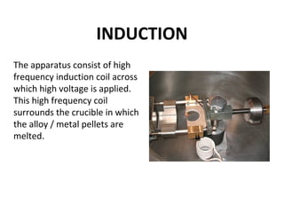
Downloaded 139 times


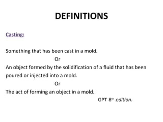

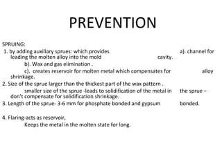
![Hi-Temp Carbon-free
investment for high
fusing alloys
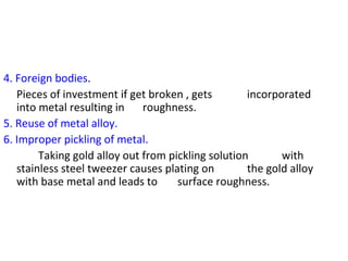
1.2%
TE at
1300-1800°F
(700-900°C
.7% Setting
Expansion
Cera-Fina Carbon-free fine
grained investment for
high fusing alloys
1.3% TE at
1300-1800°F
(700-900°C)
.3% Setting
Expansion
WiroFine partial denture
investment material
Linear thermal
expansion [%]
0,8
Bellavest® SH
Graphite-free,
phosphate-bonded
precision casting
investment material
rapidly or
conventionally
heatable casting
investment material
for crowns and bridges
made of precious
metal, non-precious
metal alloys and press
ceramic
50% BegoSol®
1.7% (total
expansion)
80% BegoSol®
2.2%(total
expansion)
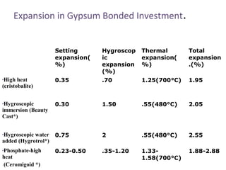
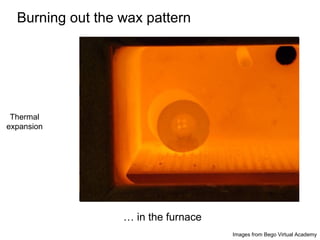
Expansion in Phosphate Bonded Investment
Material](https://image.slidesharecdn.com/castingprocedureanddefects-150827073459-lva1-app6892/85/Casting-procedure-and-defects-22-320.jpg)

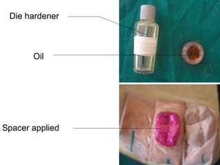
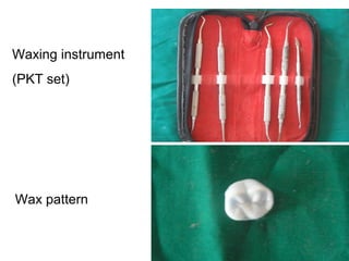

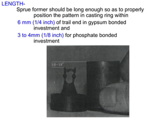
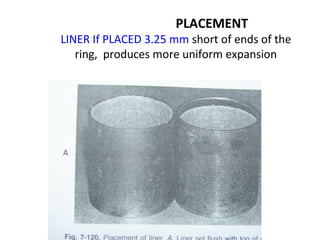
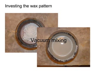
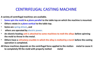
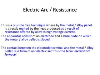
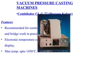

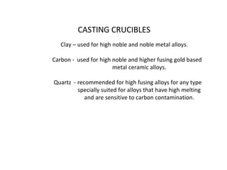
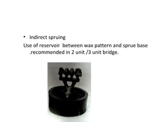
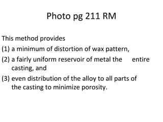
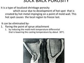
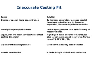

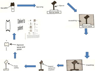
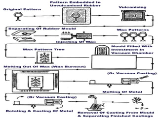
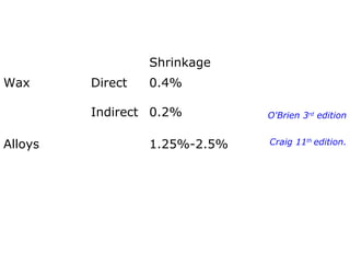
This document details the casting process in conservative dentistry, outlining definitions and steps involved in creating dental restorations. It highlights techniques such as lost-wax casting, spruing, and the use of gypsum and phosphate bonded investment materials, alongside casting machines and their operation. The document also addresses desired accuracy, defects prevention, and the types of investments and machines used in the casting procedures.


![CTEV [ clubfoot] DR ARUN LAL ,DR MOHAMED ASHRAF travancore medical college k...](https://cdn.slidesharecdn.com/ss_thumbnails/ctevclubfootdrarunlaldrmohamedashraftravancoremedicalcollegekollamkeralaindia-260208063247-18fc466c-thumbnail.jpg?width=640&height=640&fit=bounds)


![PERI-PROSTHETIC FRACTURE NAIL-PLATE CONSTRUCT [NPC].pptx](https://cdn.slidesharecdn.com/ss_thumbnails/drarunkumardrmohamedashrafperiprostheticfrasturenail-plateconstructnpc-260209164459-7e9d15a1-thumbnail.jpg?width=640&height=640&fit=bounds)


