
Recommended
Recommended
More Related Content
What's hot
What's hot (20)
Similar to Post Mortem Design Report (featuring Building Structures)
Similar to Post Mortem Design Report (featuring Building Structures) (20)
More from Carmen Chan
More from Carmen Chan (20)
Recently uploaded
Recently uploaded (20)
Post Mortem Design Report (featuring Building Structures)
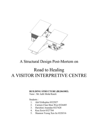
- 1. A Structural Design Post-Mortem on Road to Healing A VISITOR INTERPRETIVE CENTRE BUILDING STRUCTURE (BLD61003) Tutor : Mr Adib Mohd Ramli Students : 1. Akif Zolkeplee 0322927 2. Carmen Chan Shen Wen 0326485 3. Darishini Anandan 0327428 4. Kua Zexin 0327784 5. Shannon Yeong Xen Jie 0328316
- 2. TABLE OF CONTENTS 1. Introduction tof Visitor Interpretive Centre 2. Original Drawings of the Visitor Interpretive Centre 3. Structural Component 1 : Wall i) Fire Safety of Masonry Brick Wall ii) Fire Safety of Wooden Ventilation Block Wall 4. Structural Component 2 : Post and Beam i) Columns of the Upper Storey ii) Cantilever iii) Columns as Support for the Roof iv) Integration of the Column Support for the Roof 5. Structural Component 3 : Roof i) Roof Tiling and Underlayment ii) Integration of Gutter and Drainage 6. Feasibility of Materials and Type of Structural Components used i) Possible material selection ii) Introduction to cross laminated timber (CLT) iii) Brick wall masonry iv) Criteria for walls 7. Modified Drawings of the Visitor Interpretive Centre 8. References
- 3. 1. INTRODUCTION TO THE VISITOR INTERPRETIVE CENTRE Located in northern part of the Pusat Kawalan Kusta Negara in Sungai Buloh, The Road to Healing - a two-storey Visitor Interpretive Centre is built to educate the visitors on how the former patients of the area recover by interaction with the other patients. The massing of the centre is shaped like a ‘T’. It consists of two storeys, consisting of facilities such as the art gallery displaying the former patients’ works, the courtyard at the intersection of the spaces, a cafe that is connected to the Hokkien Association, the administration office that is linked to the neighbouring police station, a meditation space and a souvenir shop, which will direct visitors to exit the centre to the heritage houses. i) Structural Components of the Building The centre lies on a simple footing foundation. It has 3 large mono-pitch roofs supported on steel columns. All columns used as load-bearing supports for walls are cast in-situ columns. There are two types of walls - timber walls which are perforated with ventilation blocks and the plastered masonry walls. A single straight staircase connects the ground floor to the meditation space in the upper storey. For the upper storey, it is cantilevered over the first storey, providing shade and shelter over the users for the administration office and cafe. Structural Components Materials Roof Tiles Clay Roof Structural Framing Steel Wall Timber, Concrete Masonry Stairs Concrete Floor Concrete ii) Material used : The materials used for the centre are as follows :
- 4. Component 1A : WALL FIRE SAFETY OF BRICK WALL BRICK WALL Problem Statement An analysation on the structural and fire safety problems faced on the Visitor Interpretive Centre and ways to improve it. Problem I The problem with the existing bricks in the building is that it is made with stacked of fire kiln, although they’re already highly resistant to fire but the durability decreases when stack with each other. Given the height and width of the building, it is best to use other material to improve on the fire resistance capabilities. Problem II Since the brick walls are left bare, moulds and cracks tend to form due to water sipping in that can cause in degradation of material, compromising its strength and integrity. DOOR Problem Statement The existence building use timber as the back entrance heading to the office, and untreated timber enhances the intensity of fire. Furthermore, the doors doesn’t have any lining boards fixed to the structural components and other suitable materials such as insulation, air gaps and battens. Diagram above showing an untreated brick wall that are slowly being covered by mold. Source :27+ Brick Pictures | Download Free Images on Unsplash https://unsplash.com/search/photos/brick Diagram above showing a timbre door that are left to rot. Source : Old wooden door with green patina photo by Kiwihug (@kiwihug) on Unsplash https://unsplash.com/photos/-bMMBdyGIw4
- 5. Solutions : The walls are being improved by adding reinforcement within the cavities located inside the brick. To avoid such problems as the statements above, the use of reinforcement in walls allow the bricks to overcome tension forces and heavy compressive loads, with the help of reinforcement, bricks are also protected from cracks and heightened the ability to overcome lateral forces during heavy rain, wind and to also protect the occupants during the event of fire. The walls are then covered with lime based plaster, which is non-flammable and non-combustible. This is because of its low chemical reactivity but can also perform as an oxidising agent under extreme conditions. Final improvement on wall is with the added ridge on top of the wall. This is to help avoid fire from entering the vicinity in case of fire occurred in the room next door. Timber doors are replaced with casement type doors. The frame of the doors are made with aluminium which is a non-combustible material. When aluminium is presented to flame, its expansive warm conductivity enables it to rapidly disperse a lot of warmth from the fire and retain much more thermal energy from the focal point of the fire, 'cooling' the environment and confining 'extremely hot areas'. These heat levels are nearly more prominent than those of iron nor timber when presented to flame, in this manner aluminium offers a relatively higher reaction time to fire fighters. The use of dual-panned insulated glass windows, which, in addition to providing energy efficiency, also double the time it would take for fire to break the windows. Component 1A : WALL FIRE SAFETY OF BRICK WALL
- 6. Component 1A : WALL FIRE SAFETY OF BRICK WALL
- 7. Component 1B : WALL FIRE SAFETY OF WOODEN WALL WITH VENTILATION BLOCK TIMBER WALL Problem Statement The problem with the existing building is that almost 40% of the exterior walls are made with untreated or unpainted timber walls. Furthermore the interior of the timber walls have no insulation and no known connection between the other two concrete walls located side by side. This does not only reduce the strength of the building rapidly but also a fire safety concern as any structure made of timbers is rapidly destroyed in fire. Timber enhances the intensity of fire. Uses of heavy sections of timber in buildings is not desirable. Solutions : Steel Construction and CLT. Since the timber walls are a load-bearing wall, the inner parts of it are made with steel and uses a Cross Laminated Timber (CLT) as the finishes, One of the real points of interest of Cross Laminated Timber is its characteristic imperviousness to fire. CLT can be intended to suit generous imperviousness to fire and not at all like steel remains basically stable when subjected to high temperatures. CLT boards can be delivered with flame protections of 30, 60 to an hour and a half. Diagram above showcasing a type of steel framing system that are used as a reference for Carmen’s new and improved building design Source : Steel frame construction - Smarter Homes Practical advice on smarter home essentials https://www.smarterhomes.org.nz/smart-guides/c onstruction-and-materials/light-steel-frame-constr uction/ Diagram above shows pallets of Cross Laminated Timber stacks on top of each other. A design consideration to improve Carmen’s VIC. Source : Construction Concerns: Cross Laminated Timber https://www.fireengineering.com/articles/2013/07/ construction-concerns-for-firefighters-cross-lamin ated-timber.html
- 8. Component 1B : WALL FIRE SAFETY OF WOODEN WALL WITH VENTILATION BLOCK Solutions : Fiberglass and Mineral Wool Insulation. The inner hollow sections of the walls will be covered with fiberglass and mineral wool insulation which are a non-combustible materials and are known to have high fire resistance-y of up to 400 °C. The materials are also chemical free and uses no additional fire -retardant chemical treatments, furthermore, fiberglass and mineral wool are acknowledged as a fire hinder in wood and steel frames. Load Bearing Steel Connection The original design has no known connection between the concrete walls sandwiched in between the timber, if left untouched, can cause a lot of structural problems. The steel connection is designed to grip on the front and back side of the concrete walls to provide more strength to the building. Steel as a material is non-combustible and does not melt until around 1,500°C. Diagram above showing one of the common types of fibreglass and mineral wool insulation. Given the soft and malleable of nature of the product, it can be cut and be fitted in to the tiny cavity of the hollow sections of the timber walls. Source : Mineral wool vs. Fiberglass insulation - some impromptu research at the International Builders' Show - Fine Homebuilding https://www.finehomebuilding.com/2015/01/22 /mineral-wool-vs-fiberglass-insulation-some-im promptu-research-at-the-international-builders- show Diagram above shows a load bearing connection. We use this as the basis to create a more sturdy connection from concrete walls to timber wall. Source : Structural Framing http://www.bmp-group.com/products/structural-framin g
- 9. Component 1B : WALL FIRE SAFETY OF WOODEN WALL WITH VENTILATION BLOCK
- 10. Component 1B : WALL FIRE SAFETY OF WOODEN WALL WITH VENTILATION BLOCK TopView
- 11. Component 1B : WALL FIRE SAFETY OF WOODEN WALL WITH VENTILATION BLOCK
- 12. Component 2A : POST AND BEAM STRENGTH AND STABILITY OF COLUMNS The VIC is currently supported by a reinforced concrete post and beam system. However, the load distribution is not properly transferred to the foundation of the structure. The columns do not extend from the first floor to ground floor. Certain portions of the first floor cantilever out of the floor space of the ground floor, creating an overhang by the entrance of the VIC, but they are not properly supported. The structural problems identified from the post and beam system are: I. Load is not distributed uniformly to be passed on to the foundation through the columns. Ii. Cantilever slab is not properly supported by the load-bearing walls and columns. Iii. Span-depth ratio of floor slab is not accounted for. Beams are not integrated into floor slab. Columns are not aligned properly from the first floor to the ground. Cantilever slab spans too far off the edge with not enough support. Slab depth is current 240mm, not accounting beam depth and span-depth ratio.
- 13. I. Post and Beam The post and beam system can be changed by the following: A. Slab system Whether the spanning system transfers and distributes applied forces in one or two directions will determine the pattern of supports required. The building implements a one-way slab system based on the floor area. One-way slab systems transfer applied forces to a pair of parallel supporting planes, leaving two sides of spatial unit open to adjacent space. - Solution: The cantilevered slabs are a one-way slab system that transfer loads laterally from the free end to the fixed end at the load bearing wall then down to the foundation. It is also applied to structural bays which are rectangular of ratio 1.5:1 which are between two parallel load-bearing walls. They are suitable for load conditions over relatively short spans of 1.8-5.5m. The ceilings that span more than 5.5m require a transverse beam connected to a concrete frame that transfers the load into the ground. The direction of beams are placed parallel to the shorter side of the rectangular bay. Tensile reinforcements are added in the span’s direction. By adding the one-way beams. The structure’s bending and deflection moments are greatly reduced. Component 2A : POST AND BEAM STRENGTH AND STABILITY OF COLUMNS A structural grid is setup to align columns to each other for the ease of placing beams in between them. One-way slab system support the load laterally from slabs and transfers them into foundation. Thick lines - Primary beams Thin lines- Secondary beams
- 14. Component 2A : POST AND BEAM STRENGTH AND STABILITY OF COLUMNS B. Load distribution The beams of the building should be designed to carry the distributed load appropriate to their use as per UBBL 59 (6). Building structures are designed to withstand a combination of dead loads, live loads and lateral loads. Just as importantly as the magnitude of these loads is the manner in which the loads are applied to a spanning structure. Loads are applied in a concentrated or distributed manner - Concentrated loads The concentrated loads take place in parts of the building that support the most moments in the structure. These columns or bearing walls are placed in the corners of the building, supporting most of the building’s weak points. There are also additional concentrated load-bearing columns placed by the cantilevered slab to support its weight. - Beams are placed horizontally across the floor slab to uniformly distribute the loads from the superstructure to the foundation. Surface forming structures such as the reinforced concrete slab distributes the load horizontally to supporting beams in the form of distributed load. One-way slab system distributes loads evenly across the beams. Load is concentrated on the corners of the structure, transferred down the columns into the foundation. Point loads places in centre of beam are transferred through transverse beams.
- 15. Component 2A : POST AND BEAM STRENGTH AND STABILITY OF COLUMNS C. Floor system Reinforced concrete cast in-situ is used because of the small scale of the first floor making it more economical and feasible Reinforced concrete beams are designed to act together with longitudinal reinforcement in resisting applied forces. The concrete beams are formed and placed along with the slab it supports. The slab and beams are formed in a continuous pour, allowing thickness of slab to contribute to the depth of the beam and reduce the overall depth of the structure. Concrete is cast in-situ as it is more economical and feasible for the small area needed. Floor slab is cast integrally with parallel supporting beams, supported by bearing wall. Overall slab-beam depth is reduced. 400mm overall slab- beam depth 150mm slab depth Shrinkage and temperature reinforcement perpendicular to main tensile reinforcement Tensile reinforcement in the span direction
- 16. Component 2B : POST AND BEAM CANTILEVER II. Cantilever slab Cantilever slabs are a typical one way slabs. They are projections from wall face of lintel beams or floor slabs. When a load sits on a cantilever beam, two reactions occur at its support. There is the vertical shear force, which counteracts the object's weight, but the greater force is often the bending moment, which keeps the beam from rotating. Overhangs reduce the positive moment at midspan while developing a negative moment at the base of the cantilever over the support. Distribution steel reinforcement should then be provided at the transverse direction to strengthen the concrete. The top rebar from the cantilever slab span must extend into the adjacent continuous span at least for a length which is greatest of the following: - 1.5 times the length of cantilever -tension anchorage length - 0.3 times the length of adjacent continuous span Proper selection of depth and detailing of reinforcements will safeguard against excessive deflections and cracking of the cantilever slabs. TL - Tension Lap CL - Compression Lap TA - Tension Anchorage H- Slab thickness Lc - Cantilever length Ls - Length of adjacent span Overhangs reduce the positive moment at midspan while developing a negative moment at the base of the cantilever over the support. It requires an additional reinforcement to offset the forces and be structurally stable.
- 17. Component 2B : POST AND BEAM CANTILEVER The current cantilever length is 3400mm, while the length of the adjacent span is 4415mm. However, the slab cantilevers too far off the edge from the wall. Thus, an additional column is required to be added at the edge of the cantilever slab in order to avoid bending or deflection moments in the slab. The other cantilever slab over the entrance also cannot work as the cantilever length is greater than the adjacent span. Additional columns are added along the line of the wall to distribute the load of the walls from the first floor to the foundation. Additional column supports the cantilever slab that spans too long off the edge. Now, only a triangular portion of the slab overhangs. Columns are placed as supports where direct load is applied to cantilever slab. Forces now transfer from the slab to the columns, down to the foundation.
- 18. Component 2B : POST AND BEAM III. Slab depth Excessive deflections of slab will cause damage to the ceiling, floor finishes and other architectural details. To avoid this, limits are set on the span-depth ratios. The depth of the floor is directly related to the size and proportion of the structural bays it must span, the magnitude of the live loads and the strength of materials used. As a slab is usually a slender member the restrictions on the span-depth ratio become more important and this can often control the depth of slab required. Beam depth is an important consideration for reducing bending stresses and limiting vertical deflection. Having a beam span or doubling its width reduces the bending stresses by a factor of 2, but doubling the depth reduces bending stresses by a factor of 4 (DK. Ching). Currently, the slab depth is 2000mm of reinforced concrete slab. The span of the slabs vary from 2700 - 7700mm. The thickness of the load bearing walls that support these slabs are 300mm. A typical reinforced concrete slab cast in-situ is 150-300mm in thickness, for the case of this building, 150mm slab is used for saving up on economical purposes. The thickness of the walls are set as 230mm, the standard size for masonry bricks. The beam spans are placed between two columns as such the average beam span is placed at every 2400mm o.c. Rule of thumb for estimating beam depth is span/16, thus making the beam depth 400mm, inclusive of slab depth. Beams: placed 2400mm o.c. Material: Cast in-situ reinforced concrete System: One-way slab system Wall thickness: 230mm Slab thickness: 150mm Slab-beam depth: 400mm
- 19. i) Stability of the Roof Columns due to Faulty Placement of Columns Besides the columns being too skinny, certain columns that are providing support for the roof are not aligned with the columns in the upper storey. This will result in excessive point loads acting on the upper storey walls. Solution : The location of these columns are readjusted to align with the columns in the upper storey. The roof columns are properly connected to the columns in the upper storey via mechanical fixings to the plate. Component 2C : POST AND BEAM SUPPORT FOR THE ROOF Faulty location of columns that are supposed to support the roof structure The load distribution diagram shows how live loads from rain and wind act on the mono pitch roofs. The loads are then transferred to the bearing members like rafters and purlins, which are then transferred to the columns supporting the roof structure.
- 21. Component 2C : POST AND BEAM SUPPORT FOR THE ROOF i) Ratio of Cross Section to Height of Column is not Appropriate The structure of the roof support is not stable. The current length of the cross section of one roof column is 115mm. The height of the columns ranges from 700mm to 5600mm. The ratio of the size of the cross section to the height of the columns supporting the roof is too small, due to this, the reduced carrying capacity of steel columns may not be able to bear the stress of the load especially wind loads that will act upon the roof, which will result in buckling of the columns. Although multiple columns are supporting the roof, contributing to aesthetical details, but they are not be able to support the singular slab of such weight. Solution : The cross section size of the columns located at the ends of each mono-pitch roof and vital points to the upper storey wall is increased to 300mm. The remaining columns are replaced by steel roof trusses which will be attached to the vertical columns. The steel roof trusses will be connected to the main roof columns via metal plates and mechanical fixings. The bracing structure of the steel roof trusses not only can distribute the loads more evenly to the upper storey wall, it also improves the aesthetics of the roof by enhancing the visual composition of the roof. Original dimension of cross section of roof column Amended dimension of cross section of roof column Proposed steel roof truss whose bracings provide additional support to the roof Example of how bracings are connected to girder and roof column (Source from Pinterest)
- 22. iii) Rain Infiltration into the Gaps set by Roof Columns The building is mainly covered by huge single sloped roofs. The sloping roofs protect the building from external weather and therefore the rain. Since the distance between the roof structure and the walls are broaden by long steel columns, the chances of rain water to enter into the interior spaces during downpours are high. When the rain gets through the masonry walls that without damp proof course, there possibilities of crumbling plasters, bubbling paint, damp patches on wall surfaces close to the ceiling. Solution : Louvres are integrated into the columns to create a protective barrier from rain and direct sunlight from entering the interior space. Louvres are angled shutters that prevent rain and sun from entering the interior space. However, louvres still preserve the function of the openings by allowing prevailing winds to pass through the Visitor Interpretive Center, naturally ventilating it. The framing of the louvres also provide additional structural support to the roof. The louvres are made out of timber to match the timber walls of the building. They are fixed onto the steel columns through slotting them into place then nailing them down. These louvres are found in the front and back of the building. Timber louvres found in the front and back of the building Component 2C : POST AND BEAM SUPPORT FOR THE ROOF Example of connection of wooden louvres to beam and column (Sourced from Weiku) Example of connection of louvres to beam or column via support frame (Source from Exone)
- 23. Component 3A : ROOF STABILITY OF ROOF TILING ASSEMBLY i) Pitch of the roof subjected to Wind Uplift The slope for the front roof is at an inclination of less than 30 degrees, hence the front roof is subjected to negative wind pressure. ii) Underlayment and Overlapping of Roof Tiles The roof slabs are French Tuileries Romain Boyers clay roof tiles, recycled from the site of Sungai Buloh. Their main advantage is to provide cooling effects to the hot Sungai Buloh climate, while maintaining its durability and water-tight features. However, because they are long lasting, the material is also heavy. The heaviness further increases when roof tiles are composed together to form three large seamless mono-pitched roofs. This increase the stress upon the already skinny columns. Besides, the roof tiles are not overlapping one another, they have become water-shedding systems in which they allow rainwater to seep in. The roof tiles are also not connected to a roof deck, which will be affected by wind uplift. Solution : The roof tiles will remain to provide the original function, however, they will be arranged to overlap each other. The roof tiles are also secured with mechanical fixing such as nails to ensure all tiles are installed tightly to resist against wind loads. A roof deck is installed below the roof tiles. Roof tiles are not overlapping one another Roof tiles are now overlapping one another, secured with nails. Below the roof batten layer is a layer of underlayment to prevent leakage and a roof deck.
- 24. Component 3B : ROOF INTEGRATION OF THE GUTTER AND DRAINAGE Problem statement The sloped roof is built without a proper drainage system. Therefore, during rainfall the water flows through the sloped roof directly to the ground. At the same time, it also spills over to the facade of the building which may cause growth of the fungus and mold on the walls, which can be aesthetically unpleasant and also damages the structure in time. In addition, during downpours, the water enters the interior spaces because of through the opening created by long columns between the roof and walls. Solution A water drainage system should be installed on the edge of the roof to preserve the building structure. The slope allows rainwater to drain down from the roof where it is channelled through a standard guttering and then discharged by vertical pipes called downpipes to the sewer system. The image above shows the damp walls caused by rain seeping through roofs without a proper roof drainage system.
- 25. Roof Drainage system If the intensity of rainfall does not allow the gutters and downpipes to perform adequately or it is blocked by other debris, there will still be possibilities of water entering the building. Therefore it is important to consider where the water flows - is it over the edge of the sloped roof or through a dedicated overflow? Structural design factors: - Rainfall intensity - Roof catchment area - Gutter outlet (sumps) - Downpipes - Material selection of gutter - Roof pitch - Gutter style Gutter sump/outlet downpipes drain Outside box mitre Downspout pipe cleat or band elbow Gutter drop End cap Gutter hanger Diagram : Drainage system Gutter screen Component 3B : ROOF INTEGRATION OF THE GUTTER AND DRAINAGE http://www.raintamer.com/wp-content/upload s/2015/09/gutter-diagram.jpg
- 26. K- Style With an average rainfall of 250cm a year in Malaysia and a wide roof catchment area with a steeply sloped roof, the K-style gutters have been chosen as the gutter system. K-Style gutters are flat on one side, they can be nailed directly into the fascia board, which bracket installation is kept to a minimal. It provides a seamless finish, making the interior less prone to leaks than other types of gutters. This also helps avoid water damage. These gutters can hold more water compared to round style gutters or any other types of gutters 6 “ 4 ½ “ 15.24cm 11.43cm Diagram above shows a K style gutter attached with fascia board. 30 Integration of downpipes into the main columns. It is certainly possible to embed downpipes in the columns.This size of cPVC pipes are selected based on the catchment area which the downpipe has to cater. Therefore, these can be in 150mm based on the 300x300mm columns in the Visitor Interpretive Centre. The column size shall also be a function of the pipe diameter that have selected so that the concrete can flow around the pipe for the depth of the RCC column since adequate cover /space around the pipe needs to be provided. Component 3B : ROOF INTEGRATION OF THE GUTTER AND DRAINAGE
- 27. The selection and consideration of materials are influence and informed by its feasibility within the context of the climate and geology which then translates to economic sustainability. Climate is among the most significant factors on the environmental performance, life span and/or durability of construction materials in buildings. The climate of each locality presents a unique natural environment and is an effective factor on the architectural design and material use. Identifying, understanding and controlling climatic influences at the building site are perhaps the most critical part of the design process. (Ipekogˇlu, B., Böke, H., & Çizer, Ö, 2007). Geography or Geology informs the type and ways materials are used, for example Stone. Many types of stone have been used for construction In historical times, their use was determined by the proximity of the geological resources, the ease of quarrying and transportation links to the site. More recently, as transport connections and quarrying techniques have improved, quality and durability have become key determinants of building stone selection. WALL X OPTION A LIGHT WOOD FRAME CONSTRUCTION OPTION B CROSS LAMINATED TIMBER CONSTRUCTION WALL Y OPTION A BRICK MASONRY CONSTRUCTION OPTION B CONCRETE MASONRY CONSTRUCTION Component 4 : FEASIBILITY OF MATERIALS AND TYPE OF STRUCTURAL COMPONENTS USED INTRODUCTION
- 28. WALL X (option a or b) -Light Wood Frame Construction -Cross Laminated Timber WALL Y (option a or b) -Brick Masonry Construction -Concrete masonry construction LIGHT WOOD FRAME CONSTRUCTION (1st WALL TYPE OPTION 1) ● A wood light frame building can be designed to minimize waste in several ways. It can be dimensioned to utilize full sheets and lengths of wood products. Most small buildings can be framed with studs 24 inches (610 mm) o. c. rather than 16 inches (406 mm). A stud can be eliminated at each corner by using small, inexpensive metal clips to support the interior wall finish materials. If joists and rafters are aligned directly over studs, the top plate can be a single member rather than a double one. Floor joists can be spliced at points of inflection rather than over girders; this reduces bending moments and allows use of smaller joists. Roof trusses often use less wood than conventional rafters and ceiling joists. (REFER TO FIGURE A/B) a. WALL A- Studs are spaced 16 inches (406mm) The layout of the wall and its opening is not designed coordinated to the framing modules and standard details are used for corners , openings and other features. b. WALL B- Studs are spaced 24 inches (610mm) The length of the wall and location and size of the openings have been coordinated to the greatest extent possible with the 24-inch module, and redundant framing members have been eliminated. Allen, E., & Iano, J. (2009). Fundamentals of building construction: Materials and methods. Hoboken, NJ: Wiley. Wooden light frame dimensioned to utilise full length and sheet of product (FIGURE A/B) Component 4 : FEASIBILITY OF MATERIALS AND TYPE OF STRUCTURAL COMPONENTS USED POSSIBLE MATERIAL SELECTION
- 29. CLT is a panel product that is manufactured by laminating pieces of timber boards in perpendicular orientation to form the layers of the panel. The layers for the panel are usually in odd number that ranges from 3 to 7 layers. Nine layer panel is feasible but it would be impractical and uneconomical due to more layers and adhesive being used. The usual width is up to 3 m and length can be up to 18 m. Each individual lumber thickness can be in the range of 12 mm to 45mm and width in between 60 mm to 240 mm. Even though the width and length of the panel is limitless, the manufacturing facilities and transportation of the panel to construction site have also to be considered. Since CLT was pioneered and developed in temperate climate countries, the main species used for production consist of softwood that were cultivated from plantation such as spruce, fir and pine. Hardwood species have also been utilised in some CLT building projects that include birch, ash or poplar. The important criteria of selecting species for CLT is that the resources must be adequate, has the economic value as well as meeting the minimum requirement in terms of the mechanical properties. H. H., M. I., & U. A. (2008). Cross-laminated timber made from Malaysian pioneer species timber. CROSS-LAMINATED TIMBER: PRODUCTION OF PANEL USING SESENDUK TIMBER SPECIES. Retrieved October 2, 2018, from https://www.researchgate.net/publication/299467854_Cross-laminated_tim ber_made_from_Malaysian_pioneer_species_timber_Paper_presented_at_I SNaC_21-23_September_2015_PWTC_Kuala_Lumpur. Direction of grain for each layer of Cross Laminated Timber (CLT) Component 4 : FEASIBILITY OF MATERIALS AND TYPE OF STRUCTURAL COMPONENTS USED INTRODUCTION TO CROSS LAMINATED TIMBER (CLT)
- 30. WHY USE CLT Benefit to the construction industry 1. Short construction time and minimized labour usage as the panel is prefabricated 2. Less waste as panels are manufactured to specific end-use 3. Cost effectiveness as compared to concrete, masonry and steel building Benefit of the material 1. Flexibility in design for longer spans by increasing thickness 2. The cross structure of components guarantees integral stability 3. Fire resistance is better due to thicker timber member 4. Acoustic performance improves due to the mass of the wall 5. Environmentally sustainable material that has lighter carbon footprint Material properties and performance 1. Relatively high in-plane and out-of-plane strength and stiffness properties 2. High axial load capacity for walls 3. High stiffness/strength-to-mass ratio 4. High shear strength to resist horizontal loads Application of CLT 5. Termite resistance due to the glue used during the lamination process. CLT can be practically used in the following parts of a building: 1. Load bearing wall 2. Roof 3. Floor Cross Laminated Timber (CLT) used in architecture, spans a great distance. Component 4 : FEASIBILITY OF MATERIALS AND TYPE OF STRUCTURAL COMPONENTS USED INTRODUCTION TO CROSS LAMINATED TIMBER (CLT) H. H., M. I., & U. A. (2008). Cross-laminated timber made from Malaysian pioneer species timber. CROSS-LAMINATED TIMBER: PRODUCTION OF PANEL USING SESENDUK TIMBER SPECIES. Retrieved October 2, 2018, from https://www.researchgate.net/publication/29946785 4_Cross-laminated_timber_made_from_Malaysian _pioneer_species_timber_Paper_presented_at_ISN aC_21-23_September_2015_PWTC_Kuala_Lumpu r.
- 31. • Relatively small amounts of waste are generated on a construction site during brick masonry work, including partial bricks, unsatisfactory bricks, and unused mortar. These wastes generally go into landfills or are buried on the site. • Sealers applied to brick masonry to provide water repellency and protection from staining are potential sources of emissions. Solvent-based sealers generally have higher emissions than water-based products. • The thermal mass effect of brick masonry can be a useful component of fuel-saving heating and cooling strategies such as solar heating and night-time cooling. • Brick masonry is a durable form of construction that requires relatively little maintenance and can last a very long time. • Construction with brick masonry can reduce reliance on paint finishes, a source of volatile organic compounds. • Brick masonry is resistant to moisture damage and mould growth. • When a brick building is demolished, sound bricks may be cleaned of mortar and reused (once their physical properties have been verified as adequate for the new use). Brick waste can be crushed and used for landscaping. Brick and mortar waste can also be used as on-site fill. Much such waste, however, is disposed of off-site in landfills Allen, E., & Iano, J. (2009). Fundamentals of building construction: Materials and methods. Hoboken, NJ: Wiley. -Brick masonry wall requires no plastering for weather proofing allowing lower cost. Component 4 : FEASIBILITY OF MATERIALS AND TYPE OF STRUCTURAL COMPONENTS USED BRICK WALL MASONRY Why brick masonry construction (2nd wall type 1st option) -While brick may be in good condition after long periods of rain exposure the mortar bonds may be eroded.
- 32. The Economy of Concrete masonry Construction Concrete masonry is a versatile building material, and walls built from it are usually more economical than comparable ones made of brick or stone masonry: The concrete blocks themselves are cheaper on a volumetric basis and are made into a wall much more quickly because of their larger size (a single standard concrete block occupies the same volume as 12 modular bricks). Concrete blocks can be produced to required degrees of strength, and because their hollow cores allow for the easy insertion of reinforcing steel and grout, they are widely used in bearing wall construction. Concrete blocks are often used for the backup wythe behind a brick or stone facing. Block walls also accept plaster, stucco, or tile work directly, without the need for metal laths. Allen, E., & Iano, J. (2009). Fundamentals of building construction: Materials and methods. Hoboken, NJ: Wiley. Conclusion In accordance to the VIC design two desing solutions were required for the respective two types of wall identified. With each given two choices, chosen on criteria such as fire safety and economic feasibility. WALL X - required there to be fenestrations and to include wood as its main material composition while being fire resistant, WALL X is featured as an external wall, meaning it doesn't required a long period of fire resistance for these reasons CLT Was chosen as it provides design freedom, allowing there to be fenestrations and also withanding a period of time from fire. WALL Y - Is featured as internal walls thus sectioning parts of the building, material required for the walls should withstand fire, as this wall functions as a barrier to stop fire from spreading throughout the VIC, for that purpose concrete masonry wall was chosen as it was more economical compared to brick masonry wall and has better fire resistance as it bonds better with the mortar while brick masonry walls has a tendency of cracking its mortar under fire. Variety of concrete blocks used in construction Component 4 : FEASIBILITY OF MATERIALS AND TYPE OF STRUCTURAL COMPONENTS USED BRICK WALL MASONRY
- 33. REQUIREMENT & CRITERIA FOR WALL ( X & Y ) WALL LOCATION FIRE RESISTANCE WEATHER PROOFING FINISHING . X External Sufficient Maximum Wood / Fenestration . Y Internal Maximum Minimal / None Plastered WALL X ( EXTERNAL WALL ) OPTION A & B FIRE RESISTANCE WEATHER RESISTANCE DURABILITY APPLICATION LIGHT WOOD FRAME CONSTRUCTION Provides little fire - resistance unless with added retardants Requires added coating for moisture protection Threats from moisture, termites & fire Requires assembly on site, supervised by a carpenter CROSS LAMINATED TIMBER CONSTRUCTION Provides added fire resistance due to its multiple layers. Manufactured ready with coating,for moisture protection Threats from lack of maintenance Assembled in a factory, Only requires installation on site CONCLUSION Cross Laminated Timber was chosen based on the criteria of Wall X and the material’s characteristics of having treatment and coating ready from the factory to withstand moisture and termites. Not to mention the ease of installation. Reducing cost for labour and added purchases of coats and treatments WALL Y ( INTERNAL WALL ) OPTION A & B FIRE RESISTANCE WEATHER RESISTANCE DURABILITY APPLICATION BRICK MASONRY CONSTRUCTION Bond weakens under fire as the mortar cracks. Does not requires paint or plastering for waterproofing Mortar bond, will errode under rain Requires skilled masons, and come in smaller units. CONCRETE MASONRY CONSTRUCTION Has better bond with the mortar, hus having better fire resistance Requires plastering and paint Water and moisture may seep through, if without plaster layer Comes in bigger units and does not require skilled labour. CONCLUSION Concrete masonry was chosen due to its performance under fire and its overall economic cost, though it may perform badly under moisture and weather Wall Y is primarily featured as internal walls negating needs for high moisture repellence. Component 4 : CRITERIA FOR WALLS
- 35. REFERENCES Website and Book References ● Aluminium and Fire, . 2018. Aluminium and Fire, . [ONLINE] Available at: https://www.sapphirealuminium.com.au/aluminium_and_fire.html. [Accessed 02 October 2018]. ● Aluminium doors and Windows. 2018. Aluminium doors and Windows. [ONLINE] Available at: https://www.slideshare.net/JoeDerek/aluminium-doors-and-windows-62009156. [Accessed 02 October 2018]. ● Can Mold Grow on Concrete? - Polygon. 2018. Can Mold Grow on Concrete? - Polygon. [ONLINE] Available at: https://www.polygongroup.com/en-US/blog/can-mold-grow-on-concrete/. [Accessed 02 October 2018]. ● D.K. Ching, F., 2009. Building Structures Illustrated: Patterns, Systems and Design. 1st ed. US: John Wiley and Sons. ● Fire Damaged Buildings Fire damage assessment, repair & prevention for homes & other buildings. 2018. Fire Damaged Buildings Fire damage assessment, repair & prevention for homes & other buildings. [ONLINE] Available at: https://inspectapedia.com/Building_Damage/Fire_Damage_Assessment.php. [Accessed 02 October 2018] ● Hunker.com. 2018. Can Mold Develop on a Brick Wall? | Hunker. [ONLINE] Available at: https://www.hunker.com/13416134/can-mold-develop-on-a-brick-wall. [Accessed 02 October 2018]. ● Ipekogˇlu, B., Böke, H., & Çizer, Ö. (2007). Assessment of material use in relation to climate in historical buildings. Building and Environment, 42(2), 970-978. doi:10.1016/j.buildenv.2005.10.029 ● Insulation & Fire Protection | Fire Safety with Insulation. 2018. Insulation & Fire Protection | Fire Safety with Insulation. [ONLINE] Available at: https://www.kauffmanco.net/blog/insulation-fire-protection. [Accessed 02 October 2018]. ● Insulation Institute. 2018. Home Insulation | Fire Safety, Health, Mold, Corrosion. [ONLINE] Available at: https://insulationinstitute.org/im-a-homeowner/about-insulation/health-safety/. [Accessed 02 October 2018]. ● NZ Herald. 2018. Everyone can help stop the rot - NZ Herald. [ONLINE] Available at: https://www.nzherald.co.nz/nz/news/article.cfm?c_id=1&objectid=2042655. [Accessed 02 October 2018]. ● RestorationMaster. 2018. How Mold Affects Different Building Materials in your Home. [ONLINE] Available at: https://restorationmasterfinder.com/restoration/how-mold-affects-different-building-materials-in-your-home/. [Accessed 02 October 2018]. ● srcnet. 2018. GreenSpec: Cross-Laminated Timber/CLT: Fire Resistance and Rating. [ONLINE] Available at: http://www.greenspec.co.uk/building-design/crosslam-timber-fire-resistance-and-rating/. [Accessed 02 October 2018]. ● Washington Post. 2018. - The Washington Post. [ONLINE] Available at: https://www.washingtonpost.com/news/where-we-live/wp/2016/07/26/to-prevent-rot-and-mold-behind-your-homes-brick-wal ls-make-sure-the-weep-holes-are-not-blocked/?noredirect=on&utm_term=.f6a485c0fe12. [Accessed 02 October 2018]. ● Allen, E., & Iano, J. (2009). Fundamentals of building construction: Materials and methods. Hoboken, NJ: Wiley. ● H. H., M. I., & U. A. (2008). Cross-laminated timber made from Malaysian pioneer species timber. CROSS-LAMINATED TIMBER: PRODUCTION OF PANEL USING SESENDUK TIMBER SPECIES. Retrieved October 2, 2018, from https://www.researchgate.net/publication/299467854_Cross-laminated_timber_made_from_Malaysian_pioneer_species_timb er_Paper_presented_at_ISNaC_21-23_September_2015_PWTC_Kuala_Lumpur. ● Mono Pitch Roof Construction Drawings How to Build A Mono Pitch Shed Roof – sancarlosminas.info. Retrieved from https://sancarlosminas.info/50-mono-pitch-roof-construction-drawings-zc8b/mono-pitch-roof-construction-drawings-how-to- build-a-mono-pitch-shed-roof/ ● 10 key questions about exterior shading. (2014). Retrieved from https://www.constructionspecifier.com/10-key-questions-about-exterior-shading/ ● Louver. Adjustable Sun Window Louver China (Mainland) Shutters. Retrieved from http://www.weiku.com/products/14994503/Adjustable_Sun_Window_Louver.html Diagrams: ● Ramona-Elena Irimia, Marc Gottschling. 2018. Taxonomic revision of Rochefortia Sw. (Ehretiaceae, Boraginales). [ONLINE] Available at: https://doi.org/10.3897/BDJ.4.e7720. [Accessed 02 October 2018]. ● D.K. Ching, F., 2009. Building Structures Illustrated: Patterns, Systems and Design. 1st ed. US: John Wiley and Sons.