SlideShare a Scribd company logo
1 of 59
PROGRAMMABLE AC POWER CONTROL SYSTEM
MINOR PROJECT REPORT
1
Submitted in partial fulfillment of the
Requirements the award of Degree
of
Bachelor of Technology
in
ELECTRICAL & ELECTRONICS ENGINEERING
By
Amandeep Singh Rahul Rathi Avinash Jowel Aman Bharti Lasan Ahmed
05596204912) 06296204912 11715604912 11815604912 13515604912
Guided by
Mrs Amruta Pattnaik
Asstt. Professor
DEPARTMENT OF ELECTRICAL & ELECTRONICS ENGINEERING
NORTHERN INDIA ENGINEERING COLLEGE
FC-26, SASTRI PARK, DELHI—110053, (INDIA)
NOVEMBER 2016
CERTIFICATE
This is to certify that the project report entitled PROGRAMMABLE AC
POWER CONTROLSYSTEM submitted by Amandeep Singh, Aman Bharti,
Avinash Jowel, LasanAhmed, Rahul Rathi to NIEC, DELHI in partial
fulfillment for the award of Degree of Bachelor of Technology in ELECTRICAL
and ELECTRONICS Engineering is a bonafide record of the project work carried
out by them under my supervision.
Mrs Amruta Pattnaik
(Asstt. Professor)
NORTHERN INDIAENGINEERINGCOLLEGE
DELHI-110053
DECLARATION
This is to certify that Project Reportentitled “ PROGRAMMABLE AC POWER
CONTROLSYSTEM”which is submitted by me in partial fulfillment of the
requirement for the award of degree B.Tech in Electrical and Electronics
Engineering to NIEC, DELHI comprises only my original work and due
acknowledgement has been made in the text to all other material used.
Candidate’s Signature
Amandeep Singh
Rahul Rathi
Avinash Jowel
Aman Bharti
ABSTRACT
In this project we give a special idea of industrial automation, and power
controlling system.
In this project we demonstrate the idea of power control of a bulb using
microcontroller. For power control we use zero crossing and control of
firing angle concept. In this idea we save the energy compare to resistive
condition.
Mode of the project:
1. In this project we give a special idea of power control of a bulb and
display in seven segment according to speed of level. We
demonstrate the variation of speed.
2. In second we detect the measure problem in industry such as over
voltage, temperature.
3. In case of over voltage we weep the buzzer, and provide the total
protection for motor.
4. In case of over temperature problem we control the temperature on
the operation of fan automatically.
Component list:
1) Microcontroller (at 89s52).
2) Transformer (step down).
3) Diode
4) Capacitor (1000uf, 27pf, 10uf).
5) Resister (470ohm, 10k ,1k, 220k,33ohm).
6) Led.
7) Regulator (7805)
8) Seven segment display
9) Transistor (npn,pnp).
10) Resistor.
11) Switch.
12) Bt-136.( microcontroller)
13) Moc-3021. (Optocoupler)
14) 555 timer.
15) Tcp 1221.(power transistor)
16) Pc-817(optocoupler)
17) Bridge rectifier.
MODE OF PROJECT
 Power supply.
 sensor module interfacing.
 Segment display interfacing.
 Motor interfacing.
 Buzzer interfacing.
 Zero-crossing.
 Firing angle control
 Programming (assembly language).
Software used:
 Proteus software. For circuit designing.
 Kiel software. for coding
 Topwin 2008: for ic programmed to ic.
Circuit:
Working:
First of all we make the power supply. to take the step down
transformer this transformer convert 220 voltage into 9v .and after that
rectifier convert into dc voltage ,regulator provide the fixed five voltage
.and to give the all component.With the help of switch we control the
power and we give the four speed by microcontroller output according to
condition enable the transistor and operate the relay that signal give to
bulb.We detect the over temperature on the bases of variation of
resistance and out-put give to lm-358 comparator ic and output of ic
control the microcontroller.We detect the over voltage on the bases of
variation of resistance and out-put give to lm-358 comparator ic and
output of ic control the microcontroller.
XTAL2
18
XTAL1
19
ALE
30
EA
31
PSEN
29
RST
9
P0.0/AD0
39
P0.1/AD1
38
P0.2/AD2
37
P0.3/AD3
36
P0.4/AD4
35
P0.5/AD5
34
P0.6/AD6
33
P0.7/AD7
32
P1.0/T2
1
P1.1/T2EX
2
P1.2
3
P1.3
4
P1.4
5
P1.5
6
P1.6
7
P1.7
8
P3.0/RXD
10
P3.1/TXD
11
P3.2/INT0
12
P3.3/INT1
13
P3.4/T0
14
P3.7/RD
17
P3.6/WR
16
P3.5/T1
15
P2.7/A15
28
P2.0/A8
21
P2.1/A9
22
P2.2/A10
23
P2.3/A11
24
P2.4/A12
25
P2.5/A13
26
P2.6/A14
27
U?
AT89C52
TR?
TRAN-2P2S
D?
DIODE
D?
DIODE
C?
1nF
VI
1
VO
3
GND
2
U?
7805
C?
1nF
D?
LED
R?
10k
X?
CRYSTAL
C?
1nF
C?
1nF
C?
1nF
R?
10k
U2
THYRISTOR
R1
10k
R2
10k
R3
10k
R4
10k
D1
DIODE
D2
DIODE
D3
DIODE
D4
DIODE
1
2
6
4
U3
MOC3021
R
4
DC
7
Q
3
GND
1
VCC
8
TR
2
TH
6
CV
5
U4
555
R5
10k
C1
1nF
AC SOURCE
Q5
NPN
1
2
6
4
U1
MOC3021
R6
1k
THIS CHANNEL MY MOSFET /TRANSISTOR
TEMPERATURE
+88.8
Volts
+88.8
Volts
+88.8
Volts
Q1
PNP
Q2
PNP
Q3
PNP
Q4
PNP
R7
10k
R8
10k
R9
10k
R10
10k
RESEARCH AREA
 G.L Peterson ,”the wireless control system”.
 U.S Department of energy, ”Energy saver system,”
 S.kopparthi pratul K ajmera : Signal delivery for remotely
located micro-system.
 Discrete Semiconductors.”2n222222”.
 TEXAS Instruments.”max232,ht-12e and ht-12”.
 Atmel corporation,” microcontroller at89s52”.
 Digikey,”BJT,TIP”
 Programming,”8051 microcontroller Mazidi.,”
 programming ,”Kenneth j.ayala” western Carolina
university.
 Harry keybett and earl boysen,”basic electronics”.
 Front line electronic,” application of electronics”
Power
supply
Microco
ntroller
At89s52
Segment
display
Lm-339
Driver
ckt/four
channel
Opto-
coupler
555 timer
microco
ntroller
Control
panel
Temp/
voltag
e tone
sensor
Bridge
rectifier
Induction
motor
ADVANTAGE:
1. This system is applicable in industry, home, college and other
place.
2. This concept is applicable in ac fan and induction motor.
ROBLEM CONTENT:
 Components availability.
 How to decide value of components.
 Circuit designing.
 How to give the effort of soldering properly.
 Programming of sensor,
 signal sending and.
 lcd interfacing.
LEARNING OBJECTIVE:
 circuit designing on proteus software.
 Pcb layout on ARES software.
 Programming language embedded c and assembly.
 How to use keil software.
 Generate the hel file.
 How toburn the ic.
 How to do the soldering.
TECHNICAL PROSPECTIVE IDEA:
 Printed circuit board size: 9x5.
 Mdf board size 18x12.
 Height 5cm.
PROJECT PRAPOSAL METHODOLOGY:
We make a project in different mode:
1. Ist mode:
In this mode we design over all frame script such as
 Idea of project,
 Components list,
 Circuit diagram.
2. 2nd
mode:
In this mode we calculate the value of
 Components.
 Decide the component rating.
 Name of components that may be use in project.
 Purchase the components.
3. 3rd
Mode:
 In this mode we design a circuit on pcb.
 Assemble the components.
 Test the soldering dry or not.
4. 4th
mode:
in this mode we software for coding.
 We use keil software.
 We design a codein assembly or embedded c.
 We create the hex file.
5. 5th
mode:
 in this mode we design a circuit diagram on proteus for simulation
 try to simulation on proteus.
6. 6th
mode:
 In this mode we use the top-win software.
 We programmed the ic.
7. 7th
mode :in this mode we test the features of project.
TESTING TOOL:
 Multi-meter.
 Switch.
 Battery.
 Cro.
 Scope.
 Led indication.
PERFORMANCE & EVOLUTION CRITERIA:
In this project we try to best effort of technical skill. My project is prediction of
new invention. That provide new creation and scopein future.
This project demonstrate the properworking and provide complete character.
MAKING PRINTED CIRCUIT
BOARD (P.C.B.)
INTRODUCTION--
Making a Printed Circuit Board is the first step towards building electronic equipment by
any electronicindustry. A number of methods are available for making P.C.B., the simplest
method is of drawing pattern on a copper clad board with acid resistant (etchants) ink or
paint or simple nail polish on a copper clad board and do the etching process for dissolving
the rest of copper pattern in acid liquid.
MATERIAL REQUIRED
The apparatus needs for making a P.C.B. is :-
* Copper Clad Sheet
* Nail Polish or Paint
* Ferric Chloride Powder. (Fecl)
* Plastic Tray
* Tap Water etc.
PROCEDURE
The first and foremost in the process is to clean all dirt from copper sheet with say spirit or
trichloroethylene to remove traces grease or oil etc. and then wash the board under running
tap water. Dry the surface with forced warm air or just leave the board to dry naturally for
some time.
Making of the P.C.B. drawing involves some preliminary consideration such as thickness
of lines/ holes according to the components. Now draw the sketch of P.C.B. design (tracks,
rows, square) as per circuit diagram with the help of nail polish or enamel paint or any
other acid resistant liquid. Dry the point surface in open air, when it is completely dried,
the marked holes in P.C.B. may be drilled using 1Mm drill bits. In case there is any shorting
of lines due to spilling of paint, these may be removed by scraping with a blade or a knife,
after the paint has dried.
After drying, 22-30 grams of ferric chloride in 75 ml of water may be heated to about 60
degree and poured over the P.C.B. , placed with its copper side upwards in a plastic tray of
about 15*20 cm. Stirring the solution helps speedy etching. The dissolution of unwanted
copper would take about 45 minutes. If etching takes longer, the solution may be heated
again and the process repeated. The paint on the pattern can be removed P.C.B. may then
be washed and dried. Put a coat of varnish to retain the shine. Your P.C.B. is ready.
REACTION
Fecl3 + Cu ----- CuCl3 + Fe
Fecl3 + 3H2O --------- Fe (OH)3 + 3HCL
PRECAUTION
1. Add Ferric Chloride (Fecl3) carefully, without any splashing. Fecl3 is irritating to
the skin and will stain the clothes.
2. Place the board in solution with copper side up.
3. Try not to breathe the vapours. Stir the solution by giving see-saw motion to the
dish and solution in it.
4. Occasionally warm if the solution over a heater-not to boiling. After some time the
unshaded parts change their colour continue to etch. Gradually the base material
will become visible. Etch for two minutes more to get a neat pattern.
5. Don't throw away the remaining Fecl3 solution. It can be used again for next Printed
Circuit Board P.C.B.
USES:-
Printed Circuit Board are used for housing components to make a circuit for compactness,
simplicity of servicing and case of interconnection. Thus we can define the P.C.B. as :
Prinked Circuit Boards is actually a sheet of bakelite (an insulating material) on the one
side of which copper patterns are made with holes and from another side, leads of electronic
components are inserted in the proper holes and soldered to the copper points on the back.
Thus leads of electronic components terminals are joined to make electronic circuit.
In the boards copper cladding is done by pasting thin copper foil on the boards during
curing. The copper on the board is about 2 mm thick and weights an ounce per square foot.
The process of making a Printed Circuit for any application has the following steps (opted
professionally):
* Preparing the layout of the track.
* Transferring this layout photographically M the copper.
* Removing the copper in places which are not needed, by the process of etching
(chemical process)
* Drilling holes for components mounting.
PRINTED CIRCUIT BOARD
Printed circuit boards are used for housing components to make a circuit, for comactness,
simplicity of servicing and ease of interconnection. Single sided, double sided and double
sided with plated-through-hold (PYH) types of p.c boards are common today.
Boards are of two types of material (1) phenolic paper based material (2) Glass
epoxy material. Both materials are available as laminate sheets with copper cladding.
Printed circuit boards have a copper cladding on one or both sides. In both boards,
pasting thin copper foil on the board during curing does this. Boards are prepared in sizes
of 1 to 5 metre wide and upto 2 metres long. The thickness of the boards is 1.42 to 1.8mm.
The copper on the boards is about 0.2 thick and weighs and ounce per square foot.
HARDWARE/COMPONENTSDETAIL:
 POWER SUPPLY
All digital circuits require regulated power supply. In this article we are going to learn how to get
a regulated positive supply from the mains supply.
Figure 1 shows the basic block diagram of a fixed regulated power supply. Let us go through
each block.
TRANSFORMER
A transformer consists of two coils also called as “WINDINGS” namely PRIMARY &
SECONDARY. They are linked together through inductively coupled electrical conductors also
called as CORE. A changing current in the primary causes a change in the Magnetic Field in the
core & this in turn induces an alternating voltage in the secondary coil. If load is applied to the
secondary then an alternating current will flow through the load. If we consider an ideal
condition then all the energy from the primary circuit will be transferred to the secondary circuit
through the magnetic field.
So
The secondary voltage of the transformer depends on the number of turns in the Primary as well as in the
secondary..
Rectifier
A rectifier is a device that converts an AC signal into DC signal. For rectification purpose we use
a diode, a diode is a device that allows current to pass only in one direction i.e. when the anode
of the diode is positive with respect to the cathode also called as forward biased condition &
blocks current in the reversed biased condition.
Rectifier can be classified as follows:
1) Half Wave rectifier.
This is the simplest type of rectifier as you can see in the diagram a half wave rectifier consists
of only one diode. When an AC signal is applied to it during the positive half cycle the diode is
forward biased & current flows through it. But during the negative half cycle diode is reverse
biased & no current flows through it. Since only one half of the input reaches the output, it is
very inefficient to be used in power supplies.
2) Full wave rectifier.
Half wave rectifier is quite simple but it is very inefficient, for greater efficiency we would like
to use both the half cycles of the AC signal. This can be achieved by using a center tapped
transformer i.e. we would have to double the size of secondary winding & provide connection to
the center. So during the positive half cycle diode D1 conducts & D2 is in reverse biased
condition. During the negative half cycle diode D2 conducts & D1 is reverse biased. Thus we get
both the half cycles across the load.
One of the disadvantages of Full Wave Rectifier design is the necessity of using a center tapped
transformer, thus increasing the size & cost of the circuit. This can be avoided by using the Full
Wave Bridge Rectifier.
3) Bridge Rectifier.
As the name suggests it converts the full wave i.e. both the positive & the negative half cycle
into DC thus it is much more efficient than Half Wave Rectifier & that too without using a center
tapped transformer thus much more cost effective than Full Wave Rectifier.
Full Bridge Wave Rectifier consists of four diodes namely D1, D2, D3 and D4. During the
positive half cycle diodes D1 & D4 conduct whereas in the negative half cycle diodes D2 & D3
conduct thus the diodes keep switching the transformer connections so we get positive half
cycles in the output.
If we use a center tapped transformer for a bridge rectifier we can get both positive & negative
half cycles which can thus be used for generating fixed positive & fixed negative voltages.
FILTER CAPACITOR
Even though half wave & full wave rectifier give DC output, none of them provides a constant
output voltage.For this we require to smoothen the waveform received from the rectifier. This
can be done by using a capacitor at the output of the rectifier this capacitor is also called as
“FILTER CAPACITOR” or “SMOOTHING CAPACITOR” or “RESERVOIR CAPACITOR”.
Even after using this capacitor a small amount of ripple will remain.
We place the Filter Capacitor at the output of the rectifier the capacitor will charge to the peak voltage during
each half cycle then will discharge its stored energy slowly through the load while the rectified voltage drops
to zero, thus trying to keep the voltage as constant as possible.
If we go on increasing the value of the filter capacitor then the Ripple will decrease. But then the costing will
increase. The value of the Filter capacitor depends on the current consumed by the circuit, the frequency of
the waveform & the accepted ripple.
Where,
Vr= accepted ripple voltage.( should not be more than 10% of the voltage)
I= current consumed by the circuit in Amperes.
F= frequency of the waveform. A half wave rectifier has only one peak in one cycle so F=25hz
whereas a full wave rectifier has Two peaks in one cycle so F=100hz.
VOLTAGE REGULATOR
A Voltage regulator is a device which converts varying input voltage into a constant regulated
output voltage. voltage regulator can be of two types
1) Linear Voltage Regulator
Also called as Resistive Voltage regulator because they dissipate the excessive voltage
resistively as heat.
2) Switching Regulators.
They regulate the output voltage by switching the Current ON/OFF very rapidly. Since their
output is either ON or OFF it dissipates very low power thus achieving higher efficiency as
compared to linear voltage regulators. But they are more complex & generate high noise due to
their switching action. For low level of output power switching regulators tend to be costly but
for higher output wattage they are much cheaper than linear regulators.
The most commonly available Linear Positive Voltage Regulators are the 78XX series where the
XX indicates the output voltage. And 79XX series is for Negative Voltage Regulators.
After filtering the rectifier output the signal is given to a voltage regulator. The maximum input voltage that
can be applied at the input is 35V.Normally there is a 2-3 Volts drop across the regulator so the input voltage
should be at least 2-3 Volts higher than the output voltage. If the input voltage gets below the Vmin of the
regulator due to the ripple voltage or due to any other reason the voltage regulator will not be able to produce
the correct regulated voltage
DIODE
The simplest semiconductor device is made up of a sandwich of P-type
semiconducting material, with contacts provided to connect the p-and n-type layers to an
external circuit. This is a junction Diode. If the positive terminal of the battery is
connected to the p-type material (cathode) and the negative terminal to the N-type
material (Anode), a large current will flow. This is called forward current or forward
biased.
If the connections are reversed, a very little current will flow. This is because under
this condition, the p-type material will accept the electrons from the negative terminal of
the battery and the N-type material will give up its free electrons to the battery, resulting
in the state of electrical equilibrium since the N-type material has no more electrons. Thus
there will be a small current to flow and the diode is called Reverse biased.
Thus the Diode allows direct current to pass only in one direction while blocking it
in the other direction. Power diodes are used in concerting AC into DC. In this, current will
flow freely during the first half cycle (forward biased) and practically not at all during the
other half cycle (reverse biased). This makes the diode an effective rectifier,which convert
ac into pulsating dc. Signal diodes are used in radio circuits for detection. Zener diodes are
used in the circuit to control the voltage.
Some common diodes are:-
1. Zener diode.
2. Photo diode.
3. Light Emitting diode.
1. ZENER DIODE:-
A zener diode is specially designed junction diode, which can operate continuously
without being damaged in the region of reverse break down voltage. One of the most
important applications of zener diode is the design of constant voltage power supply. The
zener diode is joined in reverse bias to d.c. through a resistance R of suitable value.
2. PHOTO DIODE:-
A photo diode is a junction diode made from photo- sensitive semiconductor or
material. In such a diode, there is a provision to allow the light of suitable frequency to fall
on the p-n junction. It is reverse biased, but the voltage applied is less than the break down
voltage. As the intensity of incident light is increased, current goes on increasing till it
becomes maximum. The maximum current is called saturation current.
3. LIGHT EMITTING DIODE (LED):-
When a junction diode is forward biased, energy is released at the junction diode is
forward biased, energy is released at the junction due to recombination of electrons and
holes. In case of silicon and germanium diodes, the energy released is in infrared region.
In the junction diode made of gallium arsenate or indium phosphide, the energy is released
in visible region. Such a junction diode is called a light emitting diode or LED.
HOW LIGHT EMITTING DIODES WORK
Light emitting diodes, commonly called LEDs do dozens of different jobs and are found in all
kinds of devices. Among other things, they form the numbers on digital clocks, transmit
information from remote controls, light up watches and tell you when your appliances are turned
on. Collected together, they can form images on a jumbo television screen or illuminate a traffic
light.
Basically, LEDs are just tiny light bulbs that fit easily into an electrical circuit. But unlike ordinary
incandescent bulbs, they don't have a filament that will burn out, and they don't get especially hot.
They are illuminated solely by the movement of electrons in a semiconductor material, and they
last just as long as a standard transistor.
DIODE
A diode is the simplest sort of semiconductor device. A semiconductor is a material with a varying
ability to conduct electrical current. Most semiconductors are made of a poor conductor that has
had impurities (atoms of another material) added to it. The process of adding impurities is called
doping.
In the case of LEDs, the conductor material is typically aluminum-gallium-arsenide (AlGaAs).
In pure aluminum-gallium-arsenide, all of the atoms bond perfectly to their neighbors, leaving no
free electrons (negatively-charged particles) to conduct electric current. In doped material,
additional atoms change the balance, either adding free electrons or creating holes where electrons
can go. Either of these additions makes the material more conductive.
A semiconductor with extra electrons is called N-type material, since it has extra negatively
charged particles. In N-type material, free electrons move from a negatively charged area to a
positively charged area.
A semiconductor with extra holes is called P-type material, since it effectively has extra positively
charged particles. Electrons can jump from hole to hole, moving from a negatively charged area
to a positively charged area. As a result, the holes themselves appear to move from a positively
charged area to a negatively charged area.
A diode comprises a section of N-type material bonded to a section of P-type material, with
electrodes on each end. This arrangement conducts electricity in only one direction. When no
voltage is applied to the diode, electrons from the N-type material fill holes from the P-type
material along the junction between the layers, forming a depletion zone. In a depletion zone, the
semiconductor material is returned to its original insulating state - all of the holes are filled, so
there are no free electrons or empty spaces for electrons, and charge can't flow.
To get rid of the depletion zone, electrons should move from the N-type area to the P-type area
and holes should move in the reverse direction. This is done by connecting the N-type side of the
diode to the negative end of a circuit and the P-type side to the positive end. The free electrons in
the N-type material are repelled by the negative electrode and drawn to the positive electrode. The
holes in the P-type material move the other way. When the voltage difference between the
electrodes is high enough, the electrons in the depletion zone are boosted out of their holes and
begin moving freely again. The depletion zone disappears, and charge moves across the diode.
When the negative end of the circuit is hooked up to the N-type layer and the
positive end is hooked up to P-type layer, electrons and holes start moving and the
depletion zone disappears.
If current is run the other way, with the P-type side connected to the negative end of the circuit
and the N-type side connected to the positive end, current will not flow. The negative electrons in
the N-type material are attracted to the positive electrode. The positive holes in the P-type material
are attracted to the negative electrode. No current flows across the junction because the holes and
the electrons are each moving in the wrong direction. The depletion zone increases.
At the junction, free electrons from the N-type material fill holes from the P-type
material. This creates an insulating layer in the middle of the diode called the
depletion zone.
When the positive end of the circuit is hooked up to the N-
type layer and the negative end is hooked up to the P-type
layer, free electrons collect on one end of the diode and holes
collect on the other. The depletion zone gets bigger.
The interaction between electrons and holes in this setup has an interesting side effect - it generates
light.
HOW CAN A DIODE PRODUCE LIGHT?
Light is a form of energy that can be released by an atom. It is made up of many small particle-
like packets that have energy and momentum but no mass. These particles, called photons, are the
most basic units of light.
Photons are released as a result of moving electrons. In an atom, electrons move in orbitals around
the nucleus. Electrons in different orbitals have different amounts of energy. Electrons with greater
energy move in orbitals farther away from the nucleus.
For an electron to jump from a lower orbital to a higher orbital, something has to boost its energy
level. Conversely, an electron releases energy when it drops from a higher orbital to a lower one.
This energy is released in the form of a photon. A greater energy drop releases a higher-energy
photon, which is characterized by a higher frequency.
As free electrons moving across a diode can fall into empty holes from the P-type layer. This
involves a drop from the conduction band to a lower orbital, so the electrons release energy in the
form of photons. This happens in any diode, but the photons are seen when the diode is composed
of certain material. The atoms in a standard silicon diode, for example, are arranged in such a way
that the electron drops a relatively short distance. As a result, the photon's frequency is so low that
it is invisible to the human eye - it is in the infrared portion of the light spectrum. This isn't
necessarily a bad thing, of course: Infrared LEDs are ideal for remote controls, among other things.
Visible light-emitting diodes (VLEDs), such as the ones that light up numbers in a digital clock,
are made of materials characterized by a wider gap between the conduction band and the lower
orbitals. The size of the gap determines the frequency of the photon -- in other words, it determines
the color of the light.
While all diodes release light, most don't do it very effectively. In an ordinary diode, the
semiconductor material itself ends up absorbing a lot of the light energy.
LEDs are specially constructed to release a large number of photons outward. Additionally, they
are housed in a plastic bulb that concentrates the light in a particular direction. Most of the light
from the diode bounces off the sides of the bulb, traveling on through the rounded end.
LEDs have several advantages over conventional incandescent lamps. For one thing, they don't
have a filament that will burn out, so they last much longer. Additionally, their small plastic bulb
makes them a lot more durable. They also fit more easily into modern electronic circuits.
But the main advantage is efficiency. In conventional incandescent bulbs, the light-production
process involves generating a lot of heat (the filament must be warmed). is completely wasted
energy, unless the lamp is used as a heater, because a huge portion of the available electricity isn't
going toward producing visible light. LEDs generate very little heat, relatively. A much higher
percentage of the electrical power is going directly to generating light, which cuts down on the
electricity demands considerably.
Up until recently, LEDs were too expensive to use for most lighting applications because they're
built around advanced semiconductor material. The price of semiconductor devices has plummeted
over the past decade, however, making LEDs a more cost-effective lighting option for a wide range
of situations. While they may be more expensive than incande front, their lower cost in the long
run can make them a better buy. In the future, they will play an even bigger role in the world of
technology.
CAPACITORS
It is an electronic component whose function is to accumulate charges and then release it.
To understand the concept of capacitance, consider a pair of metal plates which all
are placed near to each other without touching. If a battery is connected to these plates
the positive pole to one and the negative pole to the other, electrons from the battery will
be attracted from the plate connected to the positive terminal of the battery. If the battery
is then disconnected, one plate will be left with an excess of electrons, the other with a
shortage, and a potential or voltage difference will exists between them. These plates will
be acting as capacitors. Capacitors are of two types: - (1) fixed type like ceramic,
polyester, electrolytic capacitors-these names refer to the
Material they
are made of
aluminium foil.
(2) Variable
type like gang
condenser in
radio or
trimmer. In
fixed type
capacitors, it has
two leads and its value is written over its body and variable type has three leads. Unit of
measurement of a capacitor is farad denoted by the symbol F. It is a very big unit of
capacitance. Small unit capacitor are pico-farad denoted by pf (Ipf=1/1000,000,000,000
f) Above all, in case of electrolytic capacitors, it's two terminal are marked as (-) and (+)
so check it while using capacitors in the circuit in right direction. Mistake can destroy the
capacitor or entire circuit in operational.
RESISTANCE
Resistance is the opposition of a material to the current. It is measured in
Ohms (
conductor is 100% efficient. To control the electron flow (current) in a predictable
manner, we use resistors. Electronic circuits use calibrated lumped resistance to
controlthe flow of current. Broadly speaking, resistor canbedivided into two groups
viz. fixed & adjustable (variable) resistors. In fixed resistors, the value is fixed &
cannot be varied. In variable resistors, the resistance value can be varied by an
adjuster knob. It can be divided into (a) Carbon composition (b) Wire wound (c)
Special type. The most common type of resistors used in our projects is carbontype.
The resistance value is normally indicated by colour bands. Each resistance has four
colours, one of the band on either side will be gold or silver, this is called fourth
band and indicates the tolerance, others three band will give the value of resistance
(see table). Forexample if a resistor has the following marking on it say red, violet,
gold. Comparing these coloured rings with the colour code, its value is 27000 ohms
or 27 kilo ohms and its tolerance is ±5%. Resistor comes in various sizes (Power
rating). The bigger, the size, the more power rating of 1/4 watts. The four colour
rings on its body tells us the value of resistor value as given below.
COLOURS CODE
Black-----------------------------------------------0
Brown ---------------------------------------------1
Red ------------------------------------------------2
Orange---------------------------------------------3
Yellow---------------------------------------------4
Green----------------------------------------------5
Blue------------------------------------------------6
Violet ----------------------------------------------7
Grey -----------------------------------------------8
White ----------------------------------------------9
The first rings give the first digit. The second ring gives the second digit. The
third ring indicates the number ofzeroes to beplaced after the digits. The fourth ring
gives tolerance (gold ±5%, silver ± 10%, No colour ± 20%).
In variable resistors, we have the dial type ofresistance boxes. Thereis a knob
with a metal pointer. This presses over brass pieces placed along a circle with some
space b/w each of them.
Resistance coils of different values are connected b/w the gaps. When the
knob is rotated, the pointer also moves over the brass pieces. Ifa gap is skipped over,
its resistance is included in the circuit. If two gaps are skipped over, the resistances
of both together are included in the circuit and so on.
A dial type of resistance box contains many dials depending upon the range,
which it has to cover. If a resistance box has to
The dial type of resistance boxes is better because the contact resistance in
this case is small & constant.
THE ADAPTING 3-TERMINAL VOLTAGE
REGULATORS FOR CONSTANT HIGH VOLTAGE
POWER SUPPLIES
One can get a constant high-voltage power supply using inexpensive 3-terminal
voltage regulators through some simple techniques described below. Depending upon the
current requirement, a reasonable load regulation can be achieved. Line regulation in all
cases is equal to that of the voltage regulator used.
Though high voltage can be obtained with suitable voltage boost circuitry using ICs
like LM 723, some advantages of the circuits presented below are: simplicity, low cost,
and practically reasonable regulation characteristics. For currents of the order of 1A or less,
only one zener and some resistors and capacitors are needed. For higher currents, one pass
transistor such as ECP055 is needed.
Before developing the final circuits, let us first understand the 3-terminal type
constant voltage regulators. Let us see the schematic in Fig. where 78XX is a 3-terminal
voltage regulator.
Schematic
for obtaining
low- voltage
regulated
output using 3-
terminal
voltage regulators.
Rectified and filtered unregulated voltage is applied at VIN and a constant voltage
appears between pins 2 and 2 of the voltage regulator. *The distribution of two currents in
the circuit (IBIAS and ILOAD) is as shown.
* It is highly recommended to use the two capacitors as shown. Electrically regulator
will be at a distance from the rectifier supply. Thus, a tantalum grade capacitor of 5mf and
rated voltage is good. Electrolytic capacitor is not suitable for it is poor in response to load
transients, which have high frequency components. At the output side a 0.22mf disc
ceramic capacitor is useful to eliminate spurious oscillations, which the regulator might
break into because of its internal high gain circuitry.
These voltage regulators have a typical bias current of 5 mA, which is reasonably
constant. By inserting a small resistor Rx between pin 2 and ground, the output voltage in
many cases. By this method voltage increment of 5 to 10 per cent is practically feasible.
However, if a high-value resistance is used to obtain a higher output voltage, a slight
variation in bias current will result in wide variation of the output voltage.
Now let us see that what can be done to get a higher but constant output voltage. If
to the circuit of Fig. resistorRY and zener Vz are added as shown in Fig., the output voltage
is now given by
VOUT=VR+VZ + IBIAS RX
A constant current flows through RY** because VOUT is constant, and small
variations in IBIAS do not change practically the operating point of Vz. This situation is
like constant current biasing of zener, which results in a very accurate setting of the zener
voltage.
** As long a sVIN>VOUT+2 volts, VOZ is constant from the reasoning of Fig, and
thus current through RY is constant.
VOZ=VR + IBIAS Rx
Here the pin 2 of the regulator is raised above ground by
Vz + IBIAS Rx. Thus, any combination of zener with a proper selectionof RY can be used.
For example, Let VR=+15 V for 7815
IBIAS=5mA
VZ=39V (standard from ECIL)
For a standard 400mW zener of ECIL make, IZMAX=10 mA. Thus, if we let pass
5mA through RY to make a 55-volt supply
55 - 39
RY = ---------------=3.2k»3.3k
5 x 10⁻³
55 - 39 - 15 1
RX = ---------------------= ---------- = 200 ohm
IBIAS 5 x 10⁻³
Schematic for constant high-voltage power supplies
It should be noted here that the maximum input voltage allowed for78XX regulators
is 35V between pins 1 and 2. We see that the actual voltage betweens pin 1 and 2 of the
regulator in this circuit is
VIN - VZ - IBIAS RX
It is therefore necessary that VIN be so chosen that voltage between pins 1 and 2 of
the IC does not exceed the maximum rating. Also, a high input-output differential voltage
VIN-VOUT means more power dissipation in the series-pass element, the regulator. Thus,
with proper selection of the input transformer voltage and capacitor, this should be
minimized.
For example, if 7805 is used, VR equals + 5V and VZ is 40V, so VOUT=45 volts. For
7805, the maximum input voltage is 35 V and the minimum 7V.
Therefore,
VIN MAX = 45 + 35 - 5 = 75 VOLTS
VIN MIN = 45 + 7 - 5 = 47 VOLTS
Thus, from no-load to full-load condition, the unregulated input voltage-including
peak ripple-should be within these limits. This gives a margin of 75-47,i.e. 28 volt. Hence,
the designer can work out the maximum transformer voltage from the no-load input voltage
chosen on the upper side.
The capacitor's value can be determined from the full load unregulated voltage
chosen. Roughly, per 100mA current, 100mf capacitor gives 1-volt peak-to-peak ripple.
Hence, capacitor's value can be determined for the desired current.
This circuit will have an excellent load and line regulation. For shot-circuit
protection, it is recommended to use a fast-blow fuse of suitable value. Although the
regulator has inherent short-circuit protection, the maximum current differs from device to
device. Adequate heat sink should be used with the regulator.
Schematic for constant high-voltage power supplies providing currents in excess of one ampere
Now if currents in excess of 1A are needed, the circuit shown in fig. is useful. This
circuit is similar to that in Fig. except that a pass transistor ECP055 is added besides a 0.5-
ohm or more resistor. This transistor bypasses the excessive current. By selecting proper
Rz the ratio of two currents passing through the regulator and transistor can be altered.
This circuit will show load and live regulation within 1% and will function properly
for VIN-VOUT as low as 4 volt. For short-circuitprotection, a fast blow fuse is recommended
as this circuit does not have inherent short-circuit protection. Adequate heat sink is to be
used for the pass transistors. For negative voltages, use 79XX series regulators and
ECN055 as the pass transistor. Some advantages of the circuits described above are: the
lowest cost among comparable performance circuits, ability to work at low input-output
differential, and flexibility in design for various applications.
So audio enthusiasts, if you are troubled by hum emanating from your power
amplifier, try this inexpensive alternative for power supply.
2.1.1 MICROCONTROLLER:
A microcontroller is a single chip that contains the processor (the CPU), non-volatile memory for
the program (ROM or flash), volatile memory for input and output (RAM), a clock and an I/O
control unit. Also called a "computer on a chip," billions of microcontroller units (MCUs) are
embedded each year in a myriad of products from toys to appliances to automobiles. For example,
a single vehicle can use 70 or more microcontrollers.
MICROCONTROLLER vs. GENERAL PURPOSE
MICROPROCESSOR:
What is the difference between a microprocessor and microcontroller? Microprocessor is the
general purpose microprocessor such as Intel’s x86 family (8086, 80386, 80486, and the Pentium)
or Motorola’s 680x0 family (68000, 68010, 68020, 68040, etc.). These microprocessors contain
no RAM, no ROM, and no I/O ports needed to fit the task at hand. This is not the case with
microcontrollers .A microcontroller has a CPU (a microprocessor )in addition to a fixed amount
of RAM ,ROM,I/O ports, and a timer, all on a single chip .In other words ,the processor, RAM,
ROM, I/O PORTS AND TIMER are all embedded together on one chip ; therefore, the designer
cannot add any external memory, I/O ,or timer to it. The fixed amount of on-chip RAM, ROM,
and number of I/O ports in microcontrollers make them ideal for many applications.
INTEL MCS -51:
The Intel MCS-51 Harvard architecture single chip microcontroller (µC) series was developed
by Intel in 1980 for use in embedded systems. Intel's original versions were popular in the 1980s
and early 1990s, but has today largely been superseded by a vast range of faster and/or functionally
enhanced 8051-compatible devices manufactured by more than 20 independent manufacturers
including Atmel, Infineon Technologies(formerly Siemens AG),Maxim Integrated Products (via
its Dallas Semiconductor subsidiary), NXP (formerly Philips Semiconductor), Nuvoton
(formerly Win bond ), ST Microelectronics , Silicon Laboratories (formerly Cygnal),Texas
Instruments and Cypress Semiconductor.
Intel's original MCS-51 family was developed using NMOS technology, but later versions,
identified by a letter C in their name (e.g., 80C51) used CMOS technology and were less power-
hungry than their NMOS predecessors. This made them more suitable for battery-powered devices.
2.1.2 IMPORTANT FEATURES AND APPLICATIONS OF
80C51:
It provides many functions (CPU, RAM, ROM, I/O, interrupt logic, timer, etc.) in a
single package
 8-bit ALU, Accumulator and 8-bit Registers; hence it is an 8 bit microcontroller
 8-bit data bus – It can access 8 bits of data in one operation
 16-bit address bus – It can access 216 memory locations – 64 KB (65536 locations) each of
RAM and ROM
 On-chip RAM – 128 bytes (data memory)
 On-chip ROM – 4 Kbyte (program memory)
 Four byte bi-directional input/output port
 UART (serial port)
 Two 16-bit Counter/timers
 Two-level interrupt priority
 Power saving mode (on some derivatives)
A particularly useful feature of the 8051 core is the inclusion of a Boolean processing engine which
allows bit-level Boolean logic operations to be carried out directly and efficiently on
internal registers and RAM. This feature helped cement the 8051's popularity in industrial control
applications. Another valued feature is that it has four separate register sets, which can be used to
greatly reduce interrupt latency compared to the more common method of storing interrupt
context on a stack.
The MCS-51 UARTs make it simple to use the chip as a serial communications interface. External
pins can be configured to connect to internal shift registers in a variety of ways, and the internal
timers can also be used, allowing serial communications in a number of modes, both synchronous
and asynchronous. Some modes allow communications with no external components. A mode
compatible with an RS-485 multi-point communications environment is achievable, but the 8051's
real strength is fitting in with existing ad-hoc protocols (e.g., when controlling serial-controlled
devices).
Once a UART, and a timer if necessary, have been configured, the programmer needs only to write
a simple interrupt routine to refill the send shift register whenever the last bit is shifted out by the
UART and/or empty the full receive shift register (copy the data somewhere else). The main
program then performs serial reads and writes simply by reading and writing 8-bit data to stacks.
MCS-51 based microcontrollers typically include one or two UARTs, two or three timers, 128 or
256 bytes of internal data RAM (16 bytes of which are bit-addressable), up to 128 bytes of I/O,
512 bytes to 64 Kb of internal program memory, and sometimes a quantity of extended data RAM
(ERAM) located in the external data space. The original 8051 core ran at 12 clock cycles per
machine cycle, with most instructions executing in one or two machine cycles. With a
12 MHz clock frequency, the 8051 could thus execute 1 million one-cycle instructions per second
or 500,000 two-cycle instructions per second. Enhanced 8051 cores are now commonly used which
run at six, four, two, or even one clock per machine cycle, and have clock frequencies of up to
100 MHz, and are thus capable of an even greater number of instructions per second. All SILabs,
some Dallas and a few Atmel devices have single cycle cores.
Common features included in modern 8051 based microcontrollers include built-in reset timers
with brown-out detection, on-chip oscillators, self-programmable Flash ROM program memory,
boot loader code in ROM, EEPROM non-volatile data storage, I²C, SPI, and USB host
interfaces, CAN or LIN bus, PWM generators, analog
comparators, A/D and D/A converters, RTCs, extra counters and timers, in-circuit debugging
facilities, more interrupt sources, and extra power saving modes.
MEMORY ARCHITECTURE:
The MCS-51 has four distinct types of memory – internal RAM, special function registers,
program memory, and external data memory.
Internal RAM (IRAM) is located from address 0 to address 0xFF. IRAM from 0x00 to 0x7F can
be accessed directly, and the bytes from 0x20 to 0x2F are also bit-addressable. IRAM from 0x80
to 0xFF must be accessed indirectly, using the @R0 or @R1 syntax, with the address to access
loaded in R0 or R1.
Special function registers (SFR) are located from address 0x80 to 0xFF, and are accessed directly
using the same instructions as for the lower half of IRAM. Some of the SFR's are also bit-
addressable.
Program memory (PMEM, though less common in usage than IRAM and XRAM) is located
starting at address 0. It may be on- or off-chip, depending on the particular model of chip being
used. Program memory is read-only, though some variants of the 8051 use on-chip flash memory
and provide a method of re-programming the memory in-system or in-application. Aside from
storing code, program memory can also store tables of constants that can be accessed by MOVC
A, @DPTR, using the 16-bit special function register DPTR.
External data memory (XRAM) also starts at address 0. It can also be on- or off-chip; what makes
it "external" is that it must be accessed using the MOVX (Move external) instruction. Many
variants of the 8051 include the standard 256 bytes of IRAM plus a few KB of XRAM on the chip.
If more XRAM is required by an application, the internal XRAM can be disabled, and all MOVX
instructions will fetch from the external bus.
INSTRUCTION SET:
The MCS-51 instruction set offers several addressing modes, including
 direct register, using ACC (the accumulator) and R0-R7
 direct memory, which access the internal RAM or the SFR's, depending on the address
 indirect memory, using R0, R1, or DPTR to hold the memory address. The instruction used
may vary to access internal RAM, external RAM, or program memory.
 individual bits of a range of IRAM and some of the SFR's
Many of the operations allow any addressing mode for the source or the destination, for example,
MOV 020h, 03fh will copy the value in memory location 0x3f in the internal RAM to the memory
location 0x20, also in internal RAM. Because the 8051 is an accumulator-based architecture, all
arithmetic operations must use the accumulator, e.g. ADD A, 020h will add the value in memory
location 0x20 in the internal RAM to the accumulator.
One does not need to master these instructions to program the 8051. With the availability of good
quality C compilers, including open source virtually all programs can be written with high level
language.
2.1.3 P89V51RD2
(8-bit 80C51 5 V low power 64 kB Flash microcontroller with 1 kB RAM)
GENERAL DESCRIPTION:
The P89V51RD2 is an 80C51 microcontroller with 64 kB Flash and 1024 bytes of data RAM.
A key feature of the P89V51RD2 is its X2 mode option. The design engineer can choose to run
the application with the conventional 80C51 clock rate (12 clocks per machine cycle) or select the
X2 mode (6 clocks per machine cycle) to achieve twice the throughput at the same clock frequency.
Another way to benefit from this feature is to keep the same performance by reducing the clock
frequency by half, thus dramatically reducing the EMI.
The Flash program memory supports both parallel programming and in serial
In-System Programming (ISP). Parallel programming mode offers gang-programming at high
speed, reducing programming costs and time to market. ISP allows a device to be reprogrammed
in the end product under software control. The capability to field/update the application firmware
makes a wide range of applications possible.
The P89V51RD2 is also In-Application Programmable (IAP), allowing the Flash
Program memory to be reconfigured even while the application is running.
FEATURES:
 80C51 Central Processing Unit
 5 V Operating voltage from 0 to 40 MHz
 64 Kb of on-chip Flash program memory with ISP (In-System Programming) and IAP (In-
Application Programming)
 Supports 12-clock (default) or 6-clock mode selection via software or ISP
 SPI (Serial Peripheral Interface) and enhanced UART
 PCA (Programmable Counter Array) with PWM and Capture/Compare functions
 Four 8-bit I/O ports with three high-current Port 1 pins (16 mA each)
 Three 16-bit timers/counters
 Programmable Watchdog timer (WDT)
 Eight interrupt sources with four priority levels
 Second DPTR register
 Low EMI mode (ALE inhibit)
 TTL- and CMOS-compatible logic levels
 Brown-out detection
 Low power modes
 Power-down mode with external interrupt wake-up
 Idle mode
 PDIP40, PLCC44 and TQFP44 packages
2.1.4 BLOCK DIAGRAM:
2.1.5 PIN DESCRIPTION:
SYMBOL PIN TYPE DESCRIPTION
P0.0 to P0.7 39 to 32 I/O Port 0: Port 0 is an 8-
bit open drain bi-
directional I/O Port.
Port 0 pins that have
‘1’s written to them
float, and in this state
can be used as high-
impedance inputs.
Port 0 is also the
multiplexed low-
order address and
data bus during
accesses to external
code and data
memory. In this
application, it uses
strong internal pull-
ups when
transitioning to ‘1’s.
Port 0 also receives
the code bytes during
the external host
mode
programming, and
outputs the code bytes
during the external
host mode
verification. External
pull-ups are
required during
program verification
or as a general
purpose I/O port.
PI.0 to P1.7 1 to 8 I/O with
internal pull-up
Port 1: Port 1 is an 8-
bit bi-directional I/O
port with
internal pull-ups. The
Port 1 pins are pulled
high by the
internal pull-ups
when ‘1’s are written
to them and can
be used as inputs in
this state. As inputs,
Port 1 pins that
are externally pulled
LOW will source
current (IIL)
because of the
internal pull-ups.
P1.5, P1.6, P1.7 have
high current drive of
16 mA. Port 1 also
receives the
low-order address
bytes during the
external host mode
programming and
verification
P1.0 1 I/O T2: External count
input to
Timer/Counter 2 or
Clock-out
from Timer/Counter
2
P1.1 2 I T2EX:
Timer/Counter 2
capture/reload trigger
and
direction control
P1.2 3 I ECI: External clock
input. This signal is
the external
clock input for the
PCA.
P1.3 4 I/O CEX0:
Capture/compare
external I/O for PCA
Module 0.
Each
capture/compare
module connects to a
Port 1 pin
for external I/O.
When not used by the
PCA, this pin can
handle standard I/O.
P1.4 5 I/O
SS: Slave port select
input for SPI
CEX1:
Capture/compare
external I/O for PCA
Module 1
P1.5 6 I/O MOSI: Master Output
Slave Input for SPI
CEX2:
Capture/compare
external I/O for PCA
Module 2
P1.6 7 I/O MISO: Master Input
Slave Output for SPI
CEX3:
Capture/compare
external I/O for PCA
Module 3
P1.7 8 I/0 SCK: Master Output
Slave Input for SPI
CEX4:
Capture/compare
external I/O for PCA
Module 4
P2.0 to P2.7 21 to 28 I/O
with internal
pull-up
Port 2: Port 2 is an 8-
bit bi-directional I/O
port with
internal pull-ups. Port
2 pins are pulled
HIGH by the
internal pull-ups
when ‘1’s are written
to them and can
be used as inputs in
this state. As inputs,
Port 2 pins that
are externally pulled
LOW will source
current (IIL)
because of the
internal pull-ups. Port
2 sends the
high-order address
byte during fetches
from external
program memory and
during accesses to
external Data
Memory that use 16-
bit address
(MOVX@DPTR). In
this
application, it uses
strong internal pull-
ups when
transitioning to ‘1’s.
Port 2 also receives
some control
signals and a partial
of high-order address
bits during
P3.0 to P3.7 10 to 17 I/O
with internal pull-
up
Port 3: Port 3 is an 8-
bit bidirectional I/O
port with
internal pull-ups. Port
3 pins are pulled
HIGH by the
internal pull-ups
when ‘1’s are written
to them and can
be used as inputs in
this state. As inputs,
Port 3 pins that
are externally pulled
LOW will source
current (IIL)
because of the
internal pull-ups. Port
3 also receives
some control signals
and a partial of high-
order address
bits during the
external host mode
programming and
verification.
P3.0 10 I RXD: serial input
port
P3.1
11 O TXD: serial output
port
P3.2 12 I
------
INT0: external
interrupt 0 input
P3.3 13 I
------
INT1: external
interrupt 1 input
P3.4 14 I T0: external count
input to
Timer/Counter 0
P3.5 15 I T1: external count
input to
Timer/Counter 1
P3.6 16 O
-----
WR: external data
memory write strobe
P3.7 17 O
-----
RD: external data
memory read strobe
-----
PSEN 29 I/O ---------
Program Store
Enable: PSEN is the
read strobe for
external program
memory. When the
device is executing
from internal
program memory,
PSEN is inactive
(HIGH). When the
device is executing
code from
external program
memory, PSEN is
activated twice each
machine cycle,
except that two PSEN
activations are
skipped during each
access to external
data memory. A
forced HIGH-to-
LOW input transition
on the PSEN pin
while the RST input
is continually held
HIGH for more
than 10 machine
cycles will cause the
device to enter
external host mode
programming.
RST 9 I Reset: While the
oscillator is running,
a HIGH logic state
on this pin for two
machine cycles will
reset the device. If
the PSEN pin is
driven by a HIGH-to-
LOW input
transition while the
RST input pin is held
HIGH, the
device will enter the
external host mode,
otherwise the
device will enter the
normal operation
mode.
----
EA 31 I External Access
Enable: EA must be
connected to VSS
in order to enable the
device to fetch code
from the
external program
memory. EA must be
strapped to VDD
for internal program
execution. However,
Security lock
level 4 will disable
EA, and program
execution is only
possible from internal
program memory.
The EA pin can
tolerate a high voltage
of 12 V.
-------
PROG/ALE 30 I/O Address Latch
Enable: ALE is the
output signal for
latching the low byte
of the address during
an access to
external memory.
This pin is also the
programming
pulse input (PROG)
for flash
programming.
Normally the
ALE is emitted at a
the crystal
frequencyand can be
used for external
timing and
clocking. One ALE
pulse is skipped
during each access
to external data
memory. However, if
AO is set to ‘1’,
ALE is disabled.
NC - I/O No Connect
XTAL1 19 I Crystal 1: Input to the
inverting oscillator
amplifier and
input to the internal
clock generator
circuits.
XTAL2 18 0 Crystal 2: Output
from the inverting
oscillator amplifier.
VDD 40 POWER SUPPLY
VSS 20 GROUND
SOFTWARE:
Appendix 1:
How to compile the demo program?
1. Start the software Keil uVision4.
2. In the menu, select Project -> New Project.
4. Select Device for Target. Click Philips -> P89V51RD2, click OK.
6. Project -> Options for Target. Select tab “Output”. Click check box
“Create HEX File”. Click OK.
7. You can press F7 or select Project -> Build Target to compile the C
program and link the object file to HEX file.
8. If everything is OK, a Hex file should be created and a message
creating new file from “main” will prompt out.
Programmable ac power control system new

More Related Content

What's hot

REAL TIME HEART BEAT MONITORING SYSTEM USING PIC16F876 MICROCONTROLLER
REAL TIME HEART BEAT MONITORING SYSTEM USING PIC16F876 MICROCONTROLLERREAL TIME HEART BEAT MONITORING SYSTEM USING PIC16F876 MICROCONTROLLER
REAL TIME HEART BEAT MONITORING SYSTEM USING PIC16F876 MICROCONTROLLERVenkata Sai Kalyan Routhu
 
Gsm based transformer fault detection system
Gsm based transformer fault detection systemGsm based transformer fault detection system
Gsm based transformer fault detection systemKabilesh K
 
Fault detection using iot PRESENTATION
Fault detection using iot PRESENTATIONFault detection using iot PRESENTATION
Fault detection using iot PRESENTATIONAnjanKumarHanumantha
 
Ppt on brake failure indicator.
Ppt on brake failure indicator.Ppt on brake failure indicator.
Ppt on brake failure indicator.mmnbaig
 
3 phase Transmission Line fault detector edit 1-3.pptx
3 phase Transmission Line fault detector edit 1-3.pptx3 phase Transmission Line fault detector edit 1-3.pptx
3 phase Transmission Line fault detector edit 1-3.pptxKrishna2017
 
Io t based electricity energy meter using esp12 and arduino at sln technologies
Io t based electricity energy meter using esp12 and arduino at sln technologiesIo t based electricity energy meter using esp12 and arduino at sln technologies
Io t based electricity energy meter using esp12 and arduino at sln technologiesSLN Technologies - Chennai
 
INTERNSHIP REPORT NTPC
INTERNSHIP REPORT NTPCINTERNSHIP REPORT NTPC
INTERNSHIP REPORT NTPCADITYA ARYAN
 
LED Chaser /Sequencer
 LED Chaser /Sequencer  LED Chaser /Sequencer
LED Chaser /Sequencer Haris Hassan
 
project presentation on "THMC"
project presentation on "THMC"project presentation on "THMC"
project presentation on "THMC"Teja venkat
 
PLC and Sensors Based Protection and Fault Detection of Induction Motors
PLC and Sensors Based Protection and Fault Detection of Induction MotorsPLC and Sensors Based Protection and Fault Detection of Induction Motors
PLC and Sensors Based Protection and Fault Detection of Induction MotorsMathankumar S
 
Micro computer control of dc drive
Micro computer control of dc driveMicro computer control of dc drive
Micro computer control of dc driveraviarmugam
 
Password based door lock system using 8051 microcontroller final report
Password based door lock system using 8051 microcontroller final reportPassword based door lock system using 8051 microcontroller final report
Password based door lock system using 8051 microcontroller final reportChinaraja Baratam
 
IRJET- IoT based Smart Energy Meter
IRJET- IoT based Smart Energy MeterIRJET- IoT based Smart Energy Meter
IRJET- IoT based Smart Energy MeterIRJET Journal
 
Heart Beat Monitoring System
Heart Beat Monitoring SystemHeart Beat Monitoring System
Heart Beat Monitoring SystemINDRANILSAIN
 
Anti sleep alarm for drivers using arduino project
Anti sleep alarm for drivers using arduino projectAnti sleep alarm for drivers using arduino project
Anti sleep alarm for drivers using arduino projectSazid Hasan Milon
 
Gas & smoke detector
Gas & smoke detectorGas & smoke detector
Gas & smoke detectorToushik Paul
 
FPGA Based Speed Control of BLDC Motor
FPGA Based Speed Control of BLDC MotorFPGA Based Speed Control of BLDC Motor
FPGA Based Speed Control of BLDC MotorRajesh Pindoriya
 

What's hot (20)

REAL TIME HEART BEAT MONITORING SYSTEM USING PIC16F876 MICROCONTROLLER
REAL TIME HEART BEAT MONITORING SYSTEM USING PIC16F876 MICROCONTROLLERREAL TIME HEART BEAT MONITORING SYSTEM USING PIC16F876 MICROCONTROLLER
REAL TIME HEART BEAT MONITORING SYSTEM USING PIC16F876 MICROCONTROLLER
 
Gsm based transformer fault detection system
Gsm based transformer fault detection systemGsm based transformer fault detection system
Gsm based transformer fault detection system
 
Fault detection using iot PRESENTATION
Fault detection using iot PRESENTATIONFault detection using iot PRESENTATION
Fault detection using iot PRESENTATION
 
Ppt on brake failure indicator.
Ppt on brake failure indicator.Ppt on brake failure indicator.
Ppt on brake failure indicator.
 
3 phase Transmission Line fault detector edit 1-3.pptx
3 phase Transmission Line fault detector edit 1-3.pptx3 phase Transmission Line fault detector edit 1-3.pptx
3 phase Transmission Line fault detector edit 1-3.pptx
 
Io t based electricity energy meter using esp12 and arduino at sln technologies
Io t based electricity energy meter using esp12 and arduino at sln technologiesIo t based electricity energy meter using esp12 and arduino at sln technologies
Io t based electricity energy meter using esp12 and arduino at sln technologies
 
INTERNSHIP REPORT NTPC
INTERNSHIP REPORT NTPCINTERNSHIP REPORT NTPC
INTERNSHIP REPORT NTPC
 
Final
FinalFinal
Final
 
LED Chaser /Sequencer
 LED Chaser /Sequencer  LED Chaser /Sequencer
LED Chaser /Sequencer
 
project presentation on "THMC"
project presentation on "THMC"project presentation on "THMC"
project presentation on "THMC"
 
PLC and Sensors Based Protection and Fault Detection of Induction Motors
PLC and Sensors Based Protection and Fault Detection of Induction MotorsPLC and Sensors Based Protection and Fault Detection of Induction Motors
PLC and Sensors Based Protection and Fault Detection of Induction Motors
 
PEL Report
PEL ReportPEL Report
PEL Report
 
Micro computer control of dc drive
Micro computer control of dc driveMicro computer control of dc drive
Micro computer control of dc drive
 
Password based door lock system using 8051 microcontroller final report
Password based door lock system using 8051 microcontroller final reportPassword based door lock system using 8051 microcontroller final report
Password based door lock system using 8051 microcontroller final report
 
IRJET- IoT based Smart Energy Meter
IRJET- IoT based Smart Energy MeterIRJET- IoT based Smart Energy Meter
IRJET- IoT based Smart Energy Meter
 
Heart Beat Monitoring System
Heart Beat Monitoring SystemHeart Beat Monitoring System
Heart Beat Monitoring System
 
Anti sleep alarm for drivers using arduino project
Anti sleep alarm for drivers using arduino projectAnti sleep alarm for drivers using arduino project
Anti sleep alarm for drivers using arduino project
 
Smart irrigation ppt
Smart irrigation pptSmart irrigation ppt
Smart irrigation ppt
 
Gas & smoke detector
Gas & smoke detectorGas & smoke detector
Gas & smoke detector
 
FPGA Based Speed Control of BLDC Motor
FPGA Based Speed Control of BLDC MotorFPGA Based Speed Control of BLDC Motor
FPGA Based Speed Control of BLDC Motor
 

Similar to Programmable ac power control system new

BUILD DC TIME DELAY RELAY USING PUT ON ZERO (0) PCB .pptx
BUILD DC TIME DELAY RELAY USING PUT ON ZERO (0) PCB .pptxBUILD DC TIME DELAY RELAY USING PUT ON ZERO (0) PCB .pptx
BUILD DC TIME DELAY RELAY USING PUT ON ZERO (0) PCB .pptxAshish Sadavarti
 
SolAero Tech Intern_Project Overview
SolAero Tech Intern_Project OverviewSolAero Tech Intern_Project Overview
SolAero Tech Intern_Project OverviewEddie Benitez-Jones
 
MICROPROCESSOR BASED SUN TRACKING SOLAR PANEL SYSTEM TO MAXIMIZE ENERGY GENER...
MICROPROCESSOR BASED SUN TRACKING SOLAR PANEL SYSTEM TO MAXIMIZE ENERGY GENER...MICROPROCESSOR BASED SUN TRACKING SOLAR PANEL SYSTEM TO MAXIMIZE ENERGY GENER...
MICROPROCESSOR BASED SUN TRACKING SOLAR PANEL SYSTEM TO MAXIMIZE ENERGY GENER...moiz89
 
Automatic Power Factor Corrector Using Arduino report
Automatic Power Factor Corrector Using Arduino reportAutomatic Power Factor Corrector Using Arduino report
Automatic Power Factor Corrector Using Arduino reportSelf-employed
 
TRANSFORMER FAULT DETECTION AND MONITORING
TRANSFORMER FAULT DETECTION AND MONITORINGTRANSFORMER FAULT DETECTION AND MONITORING
TRANSFORMER FAULT DETECTION AND MONITORINGIRJET Journal
 
INTELLIGENT HELMET FOR COAL MINERS
INTELLIGENT HELMET FOR COAL MINERSINTELLIGENT HELMET FOR COAL MINERS
INTELLIGENT HELMET FOR COAL MINERSARUN P S
 
Thermal Artwork Transferring Machine for PCB Manufacturing
Thermal Artwork Transferring Machine for PCB ManufacturingThermal Artwork Transferring Machine for PCB Manufacturing
Thermal Artwork Transferring Machine for PCB ManufacturingIRJET Journal
 
75600403 automatic-plant-irrigation-system
75600403 automatic-plant-irrigation-system75600403 automatic-plant-irrigation-system
75600403 automatic-plant-irrigation-systemstk25
 
IRJET- Design and Implementation of High Speed, Low Power Charge Shared R...
IRJET-  	  Design and Implementation of High Speed, Low Power Charge Shared R...IRJET-  	  Design and Implementation of High Speed, Low Power Charge Shared R...
IRJET- Design and Implementation of High Speed, Low Power Charge Shared R...IRJET Journal
 
Mini project electronic workshop
Mini project electronic workshopMini project electronic workshop
Mini project electronic workshopamerrudin azizi
 
under grund fault ppt (1).pptx
under grund fault ppt (1).pptxunder grund fault ppt (1).pptx
under grund fault ppt (1).pptxPoojaG86
 
Alcohol sensing alert with engine locking project
Alcohol sensing alert with engine locking projectAlcohol sensing alert with engine locking project
Alcohol sensing alert with engine locking projecthemanth prudhvi jidugu
 
EMCLO PROJECT: EMC DESIGN METHODOLOGY FOR LAYOUT OPTIMIZATION
EMCLO PROJECT: EMC DESIGN METHODOLOGY FOR LAYOUT OPTIMIZATIONEMCLO PROJECT: EMC DESIGN METHODOLOGY FOR LAYOUT OPTIMIZATION
EMCLO PROJECT: EMC DESIGN METHODOLOGY FOR LAYOUT OPTIMIZATIONPiero Belforte
 
Presentation final 4.29
Presentation final 4.29Presentation final 4.29
Presentation final 4.29Xueyin Shi
 

Similar to Programmable ac power control system new (20)

BUILD DC TIME DELAY RELAY USING PUT ON ZERO (0) PCB .pptx
BUILD DC TIME DELAY RELAY USING PUT ON ZERO (0) PCB .pptxBUILD DC TIME DELAY RELAY USING PUT ON ZERO (0) PCB .pptx
BUILD DC TIME DELAY RELAY USING PUT ON ZERO (0) PCB .pptx
 
Wireless multimeter Black book
Wireless multimeter Black bookWireless multimeter Black book
Wireless multimeter Black book
 
SolAero Tech Intern_Project Overview
SolAero Tech Intern_Project OverviewSolAero Tech Intern_Project Overview
SolAero Tech Intern_Project Overview
 
5 FINAL PROJECT REPORT
5 FINAL PROJECT REPORT5 FINAL PROJECT REPORT
5 FINAL PROJECT REPORT
 
MICROPROCESSOR BASED SUN TRACKING SOLAR PANEL SYSTEM TO MAXIMIZE ENERGY GENER...
MICROPROCESSOR BASED SUN TRACKING SOLAR PANEL SYSTEM TO MAXIMIZE ENERGY GENER...MICROPROCESSOR BASED SUN TRACKING SOLAR PANEL SYSTEM TO MAXIMIZE ENERGY GENER...
MICROPROCESSOR BASED SUN TRACKING SOLAR PANEL SYSTEM TO MAXIMIZE ENERGY GENER...
 
Automatic Power Factor Corrector Using Arduino report
Automatic Power Factor Corrector Using Arduino reportAutomatic Power Factor Corrector Using Arduino report
Automatic Power Factor Corrector Using Arduino report
 
TRANSFORMER FAULT DETECTION AND MONITORING
TRANSFORMER FAULT DETECTION AND MONITORINGTRANSFORMER FAULT DETECTION AND MONITORING
TRANSFORMER FAULT DETECTION AND MONITORING
 
INTELLIGENT HELMET FOR COAL MINERS
INTELLIGENT HELMET FOR COAL MINERSINTELLIGENT HELMET FOR COAL MINERS
INTELLIGENT HELMET FOR COAL MINERS
 
Thermal Artwork Transferring Machine for PCB Manufacturing
Thermal Artwork Transferring Machine for PCB ManufacturingThermal Artwork Transferring Machine for PCB Manufacturing
Thermal Artwork Transferring Machine for PCB Manufacturing
 
75600403 automatic-plant-irrigation-system
75600403 automatic-plant-irrigation-system75600403 automatic-plant-irrigation-system
75600403 automatic-plant-irrigation-system
 
surabhi
surabhisurabhi
surabhi
 
IRJET- Design and Implementation of High Speed, Low Power Charge Shared R...
IRJET-  	  Design and Implementation of High Speed, Low Power Charge Shared R...IRJET-  	  Design and Implementation of High Speed, Low Power Charge Shared R...
IRJET- Design and Implementation of High Speed, Low Power Charge Shared R...
 
Mini project electronic workshop
Mini project electronic workshopMini project electronic workshop
Mini project electronic workshop
 
Capacitance Type Level Transmitter for liquids.pdf
Capacitance Type Level Transmitter for liquids.pdfCapacitance Type Level Transmitter for liquids.pdf
Capacitance Type Level Transmitter for liquids.pdf
 
under grund fault ppt (1).pptx
under grund fault ppt (1).pptxunder grund fault ppt (1).pptx
under grund fault ppt (1).pptx
 
Alcohol sensing alert with engine locking project
Alcohol sensing alert with engine locking projectAlcohol sensing alert with engine locking project
Alcohol sensing alert with engine locking project
 
Major
MajorMajor
Major
 
final report
final reportfinal report
final report
 
EMCLO PROJECT: EMC DESIGN METHODOLOGY FOR LAYOUT OPTIMIZATION
EMCLO PROJECT: EMC DESIGN METHODOLOGY FOR LAYOUT OPTIMIZATIONEMCLO PROJECT: EMC DESIGN METHODOLOGY FOR LAYOUT OPTIMIZATION
EMCLO PROJECT: EMC DESIGN METHODOLOGY FOR LAYOUT OPTIMIZATION
 
Presentation final 4.29
Presentation final 4.29Presentation final 4.29
Presentation final 4.29
 

Recently uploaded

Introduction to Data Visualization,Matplotlib.pdf
Introduction to Data Visualization,Matplotlib.pdfIntroduction to Data Visualization,Matplotlib.pdf
Introduction to Data Visualization,Matplotlib.pdfsumitt6_25730773
 
Basic Electronics for diploma students as per technical education Kerala Syll...
Basic Electronics for diploma students as per technical education Kerala Syll...Basic Electronics for diploma students as per technical education Kerala Syll...
Basic Electronics for diploma students as per technical education Kerala Syll...ppkakm
 
Introduction to Artificial Intelligence ( AI)
Introduction to Artificial Intelligence ( AI)Introduction to Artificial Intelligence ( AI)
Introduction to Artificial Intelligence ( AI)ChandrakantDivate1
 
Max. shear stress theory-Maximum Shear Stress Theory ​ Maximum Distortional ...
Max. shear stress theory-Maximum Shear Stress Theory ​  Maximum Distortional ...Max. shear stress theory-Maximum Shear Stress Theory ​  Maximum Distortional ...
Max. shear stress theory-Maximum Shear Stress Theory ​ Maximum Distortional ...ronahami
 
Digital Communication Essentials: DPCM, DM, and ADM .pptx
Digital Communication Essentials: DPCM, DM, and ADM .pptxDigital Communication Essentials: DPCM, DM, and ADM .pptx
Digital Communication Essentials: DPCM, DM, and ADM .pptxpritamlangde
 
NO1 Top No1 Amil Baba In Azad Kashmir, Kashmir Black Magic Specialist Expert ...
NO1 Top No1 Amil Baba In Azad Kashmir, Kashmir Black Magic Specialist Expert ...NO1 Top No1 Amil Baba In Azad Kashmir, Kashmir Black Magic Specialist Expert ...
NO1 Top No1 Amil Baba In Azad Kashmir, Kashmir Black Magic Specialist Expert ...Amil baba
 
Online food ordering system project report.pdf
Online food ordering system project report.pdfOnline food ordering system project report.pdf
Online food ordering system project report.pdfKamal Acharya
 
School management system project Report.pdf
School management system project Report.pdfSchool management system project Report.pdf
School management system project Report.pdfKamal Acharya
 
S1S2 B.Arch MGU - HOA1&2 Module 3 -Temple Architecture of Kerala.pptx
S1S2 B.Arch MGU - HOA1&2 Module 3 -Temple Architecture of Kerala.pptxS1S2 B.Arch MGU - HOA1&2 Module 3 -Temple Architecture of Kerala.pptx
S1S2 B.Arch MGU - HOA1&2 Module 3 -Temple Architecture of Kerala.pptxSCMS School of Architecture
 
Hospital management system project report.pdf
Hospital management system project report.pdfHospital management system project report.pdf
Hospital management system project report.pdfKamal Acharya
 
fitting shop and tools used in fitting shop .ppt
fitting shop and tools used in fitting shop .pptfitting shop and tools used in fitting shop .ppt
fitting shop and tools used in fitting shop .pptAfnanAhmad53
 
UNIT 4 PTRP final Convergence in probability.pptx
UNIT 4 PTRP final Convergence in probability.pptxUNIT 4 PTRP final Convergence in probability.pptx
UNIT 4 PTRP final Convergence in probability.pptxkalpana413121
 
Post office management system project ..pdf
Post office management system project ..pdfPost office management system project ..pdf
Post office management system project ..pdfKamal Acharya
 
XXXXXXXXXXXXXXXXXXXXXXXXXXXXXXXXXXXXXXXXXXXXXXXXXXXX
XXXXXXXXXXXXXXXXXXXXXXXXXXXXXXXXXXXXXXXXXXXXXXXXXXXXXXXXXXXXXXXXXXXXXXXXXXXXXXXXXXXXXXXXXXXXXXXXXXXXXXXX
XXXXXXXXXXXXXXXXXXXXXXXXXXXXXXXXXXXXXXXXXXXXXXXXXXXXssuser89054b
 
Introduction to Geographic Information Systems
Introduction to Geographic Information SystemsIntroduction to Geographic Information Systems
Introduction to Geographic Information SystemsAnge Felix NSANZIYERA
 
Worksharing and 3D Modeling with Revit.pptx
Worksharing and 3D Modeling with Revit.pptxWorksharing and 3D Modeling with Revit.pptx
Worksharing and 3D Modeling with Revit.pptxMustafa Ahmed
 
Unit 4_Part 1 CSE2001 Exception Handling and Function Template and Class Temp...
Unit 4_Part 1 CSE2001 Exception Handling and Function Template and Class Temp...Unit 4_Part 1 CSE2001 Exception Handling and Function Template and Class Temp...
Unit 4_Part 1 CSE2001 Exception Handling and Function Template and Class Temp...drmkjayanthikannan
 
Online electricity billing project report..pdf
Online electricity billing project report..pdfOnline electricity billing project report..pdf
Online electricity billing project report..pdfKamal Acharya
 
Design For Accessibility: Getting it right from the start
Design For Accessibility: Getting it right from the startDesign For Accessibility: Getting it right from the start
Design For Accessibility: Getting it right from the startQuintin Balsdon
 

Recently uploaded (20)

Introduction to Data Visualization,Matplotlib.pdf
Introduction to Data Visualization,Matplotlib.pdfIntroduction to Data Visualization,Matplotlib.pdf
Introduction to Data Visualization,Matplotlib.pdf
 
Cara Menggugurkan Sperma Yang Masuk Rahim Biyar Tidak Hamil
Cara Menggugurkan Sperma Yang Masuk Rahim Biyar Tidak HamilCara Menggugurkan Sperma Yang Masuk Rahim Biyar Tidak Hamil
Cara Menggugurkan Sperma Yang Masuk Rahim Biyar Tidak Hamil
 
Basic Electronics for diploma students as per technical education Kerala Syll...
Basic Electronics for diploma students as per technical education Kerala Syll...Basic Electronics for diploma students as per technical education Kerala Syll...
Basic Electronics for diploma students as per technical education Kerala Syll...
 
Introduction to Artificial Intelligence ( AI)
Introduction to Artificial Intelligence ( AI)Introduction to Artificial Intelligence ( AI)
Introduction to Artificial Intelligence ( AI)
 
Max. shear stress theory-Maximum Shear Stress Theory ​ Maximum Distortional ...
Max. shear stress theory-Maximum Shear Stress Theory ​  Maximum Distortional ...Max. shear stress theory-Maximum Shear Stress Theory ​  Maximum Distortional ...
Max. shear stress theory-Maximum Shear Stress Theory ​ Maximum Distortional ...
 
Digital Communication Essentials: DPCM, DM, and ADM .pptx
Digital Communication Essentials: DPCM, DM, and ADM .pptxDigital Communication Essentials: DPCM, DM, and ADM .pptx
Digital Communication Essentials: DPCM, DM, and ADM .pptx
 
NO1 Top No1 Amil Baba In Azad Kashmir, Kashmir Black Magic Specialist Expert ...
NO1 Top No1 Amil Baba In Azad Kashmir, Kashmir Black Magic Specialist Expert ...NO1 Top No1 Amil Baba In Azad Kashmir, Kashmir Black Magic Specialist Expert ...
NO1 Top No1 Amil Baba In Azad Kashmir, Kashmir Black Magic Specialist Expert ...
 
Online food ordering system project report.pdf
Online food ordering system project report.pdfOnline food ordering system project report.pdf
Online food ordering system project report.pdf
 
School management system project Report.pdf
School management system project Report.pdfSchool management system project Report.pdf
School management system project Report.pdf
 
S1S2 B.Arch MGU - HOA1&2 Module 3 -Temple Architecture of Kerala.pptx
S1S2 B.Arch MGU - HOA1&2 Module 3 -Temple Architecture of Kerala.pptxS1S2 B.Arch MGU - HOA1&2 Module 3 -Temple Architecture of Kerala.pptx
S1S2 B.Arch MGU - HOA1&2 Module 3 -Temple Architecture of Kerala.pptx
 
Hospital management system project report.pdf
Hospital management system project report.pdfHospital management system project report.pdf
Hospital management system project report.pdf
 
fitting shop and tools used in fitting shop .ppt
fitting shop and tools used in fitting shop .pptfitting shop and tools used in fitting shop .ppt
fitting shop and tools used in fitting shop .ppt
 
UNIT 4 PTRP final Convergence in probability.pptx
UNIT 4 PTRP final Convergence in probability.pptxUNIT 4 PTRP final Convergence in probability.pptx
UNIT 4 PTRP final Convergence in probability.pptx
 
Post office management system project ..pdf
Post office management system project ..pdfPost office management system project ..pdf
Post office management system project ..pdf
 
XXXXXXXXXXXXXXXXXXXXXXXXXXXXXXXXXXXXXXXXXXXXXXXXXXXX
XXXXXXXXXXXXXXXXXXXXXXXXXXXXXXXXXXXXXXXXXXXXXXXXXXXXXXXXXXXXXXXXXXXXXXXXXXXXXXXXXXXXXXXXXXXXXXXXXXXXXXXX
XXXXXXXXXXXXXXXXXXXXXXXXXXXXXXXXXXXXXXXXXXXXXXXXXXXX
 
Introduction to Geographic Information Systems
Introduction to Geographic Information SystemsIntroduction to Geographic Information Systems
Introduction to Geographic Information Systems
 
Worksharing and 3D Modeling with Revit.pptx
Worksharing and 3D Modeling with Revit.pptxWorksharing and 3D Modeling with Revit.pptx
Worksharing and 3D Modeling with Revit.pptx
 
Unit 4_Part 1 CSE2001 Exception Handling and Function Template and Class Temp...
Unit 4_Part 1 CSE2001 Exception Handling and Function Template and Class Temp...Unit 4_Part 1 CSE2001 Exception Handling and Function Template and Class Temp...
Unit 4_Part 1 CSE2001 Exception Handling and Function Template and Class Temp...
 
Online electricity billing project report..pdf
Online electricity billing project report..pdfOnline electricity billing project report..pdf
Online electricity billing project report..pdf
 
Design For Accessibility: Getting it right from the start
Design For Accessibility: Getting it right from the startDesign For Accessibility: Getting it right from the start
Design For Accessibility: Getting it right from the start
 

Programmable ac power control system new

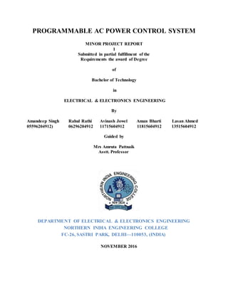
  • 1. PROGRAMMABLE AC POWER CONTROL SYSTEM MINOR PROJECT REPORT 1 Submitted in partial fulfillment of the Requirements the award of Degree of Bachelor of Technology in ELECTRICAL & ELECTRONICS ENGINEERING By Amandeep Singh Rahul Rathi Avinash Jowel Aman Bharti Lasan Ahmed 05596204912) 06296204912 11715604912 11815604912 13515604912 Guided by Mrs Amruta Pattnaik Asstt. Professor DEPARTMENT OF ELECTRICAL & ELECTRONICS ENGINEERING NORTHERN INDIA ENGINEERING COLLEGE FC-26, SASTRI PARK, DELHI—110053, (INDIA) NOVEMBER 2016
  • 2. CERTIFICATE This is to certify that the project report entitled PROGRAMMABLE AC POWER CONTROLSYSTEM submitted by Amandeep Singh, Aman Bharti, Avinash Jowel, LasanAhmed, Rahul Rathi to NIEC, DELHI in partial fulfillment for the award of Degree of Bachelor of Technology in ELECTRICAL and ELECTRONICS Engineering is a bonafide record of the project work carried out by them under my supervision. Mrs Amruta Pattnaik (Asstt. Professor) NORTHERN INDIAENGINEERINGCOLLEGE DELHI-110053 DECLARATION
  • 3. This is to certify that Project Reportentitled “ PROGRAMMABLE AC POWER CONTROLSYSTEM”which is submitted by me in partial fulfillment of the requirement for the award of degree B.Tech in Electrical and Electronics Engineering to NIEC, DELHI comprises only my original work and due acknowledgement has been made in the text to all other material used. Candidate’s Signature Amandeep Singh Rahul Rathi Avinash Jowel Aman Bharti
  • 4. ABSTRACT In this project we give a special idea of industrial automation, and power controlling system. In this project we demonstrate the idea of power control of a bulb using microcontroller. For power control we use zero crossing and control of firing angle concept. In this idea we save the energy compare to resistive condition. Mode of the project: 1. In this project we give a special idea of power control of a bulb and display in seven segment according to speed of level. We demonstrate the variation of speed. 2. In second we detect the measure problem in industry such as over voltage, temperature. 3. In case of over voltage we weep the buzzer, and provide the total protection for motor. 4. In case of over temperature problem we control the temperature on the operation of fan automatically.
  • 5. Component list: 1) Microcontroller (at 89s52). 2) Transformer (step down). 3) Diode 4) Capacitor (1000uf, 27pf, 10uf). 5) Resister (470ohm, 10k ,1k, 220k,33ohm). 6) Led. 7) Regulator (7805) 8) Seven segment display 9) Transistor (npn,pnp). 10) Resistor. 11) Switch. 12) Bt-136.( microcontroller) 13) Moc-3021. (Optocoupler) 14) 555 timer. 15) Tcp 1221.(power transistor) 16) Pc-817(optocoupler) 17) Bridge rectifier.
  • 6. MODE OF PROJECT  Power supply.  sensor module interfacing.  Segment display interfacing.  Motor interfacing.  Buzzer interfacing.  Zero-crossing.  Firing angle control  Programming (assembly language). Software used:  Proteus software. For circuit designing.  Kiel software. for coding  Topwin 2008: for ic programmed to ic.
  • 7. Circuit: Working: First of all we make the power supply. to take the step down transformer this transformer convert 220 voltage into 9v .and after that rectifier convert into dc voltage ,regulator provide the fixed five voltage .and to give the all component.With the help of switch we control the power and we give the four speed by microcontroller output according to condition enable the transistor and operate the relay that signal give to bulb.We detect the over temperature on the bases of variation of resistance and out-put give to lm-358 comparator ic and output of ic control the microcontroller.We detect the over voltage on the bases of variation of resistance and out-put give to lm-358 comparator ic and output of ic control the microcontroller. XTAL2 18 XTAL1 19 ALE 30 EA 31 PSEN 29 RST 9 P0.0/AD0 39 P0.1/AD1 38 P0.2/AD2 37 P0.3/AD3 36 P0.4/AD4 35 P0.5/AD5 34 P0.6/AD6 33 P0.7/AD7 32 P1.0/T2 1 P1.1/T2EX 2 P1.2 3 P1.3 4 P1.4 5 P1.5 6 P1.6 7 P1.7 8 P3.0/RXD 10 P3.1/TXD 11 P3.2/INT0 12 P3.3/INT1 13 P3.4/T0 14 P3.7/RD 17 P3.6/WR 16 P3.5/T1 15 P2.7/A15 28 P2.0/A8 21 P2.1/A9 22 P2.2/A10 23 P2.3/A11 24 P2.4/A12 25 P2.5/A13 26 P2.6/A14 27 U? AT89C52 TR? TRAN-2P2S D? DIODE D? DIODE C? 1nF VI 1 VO 3 GND 2 U? 7805 C? 1nF D? LED R? 10k X? CRYSTAL C? 1nF C? 1nF C? 1nF R? 10k U2 THYRISTOR R1 10k R2 10k R3 10k R4 10k D1 DIODE D2 DIODE D3 DIODE D4 DIODE 1 2 6 4 U3 MOC3021 R 4 DC 7 Q 3 GND 1 VCC 8 TR 2 TH 6 CV 5 U4 555 R5 10k C1 1nF AC SOURCE Q5 NPN 1 2 6 4 U1 MOC3021 R6 1k THIS CHANNEL MY MOSFET /TRANSISTOR TEMPERATURE +88.8 Volts +88.8 Volts +88.8 Volts Q1 PNP Q2 PNP Q3 PNP Q4 PNP R7 10k R8 10k R9 10k R10 10k
  • 8. RESEARCH AREA  G.L Peterson ,”the wireless control system”.  U.S Department of energy, ”Energy saver system,”  S.kopparthi pratul K ajmera : Signal delivery for remotely located micro-system.  Discrete Semiconductors.”2n222222”.  TEXAS Instruments.”max232,ht-12e and ht-12”.  Atmel corporation,” microcontroller at89s52”.  Digikey,”BJT,TIP”  Programming,”8051 microcontroller Mazidi.,”  programming ,”Kenneth j.ayala” western Carolina university.  Harry keybett and earl boysen,”basic electronics”.  Front line electronic,” application of electronics”
  • 10. ADVANTAGE: 1. This system is applicable in industry, home, college and other place. 2. This concept is applicable in ac fan and induction motor. ROBLEM CONTENT:  Components availability.  How to decide value of components.  Circuit designing.  How to give the effort of soldering properly.  Programming of sensor,  signal sending and.  lcd interfacing. LEARNING OBJECTIVE:  circuit designing on proteus software.  Pcb layout on ARES software.  Programming language embedded c and assembly.  How to use keil software.  Generate the hel file.  How toburn the ic.  How to do the soldering. TECHNICAL PROSPECTIVE IDEA:  Printed circuit board size: 9x5.  Mdf board size 18x12.  Height 5cm.
  • 11. PROJECT PRAPOSAL METHODOLOGY: We make a project in different mode: 1. Ist mode: In this mode we design over all frame script such as  Idea of project,  Components list,  Circuit diagram. 2. 2nd mode: In this mode we calculate the value of  Components.  Decide the component rating.  Name of components that may be use in project.  Purchase the components. 3. 3rd Mode:  In this mode we design a circuit on pcb.  Assemble the components.  Test the soldering dry or not. 4. 4th mode: in this mode we software for coding.  We use keil software.  We design a codein assembly or embedded c.  We create the hex file. 5. 5th mode:  in this mode we design a circuit diagram on proteus for simulation  try to simulation on proteus. 6. 6th mode:  In this mode we use the top-win software.  We programmed the ic. 7. 7th mode :in this mode we test the features of project.
  • 12. TESTING TOOL:  Multi-meter.  Switch.  Battery.  Cro.  Scope.  Led indication. PERFORMANCE & EVOLUTION CRITERIA: In this project we try to best effort of technical skill. My project is prediction of new invention. That provide new creation and scopein future. This project demonstrate the properworking and provide complete character. MAKING PRINTED CIRCUIT BOARD (P.C.B.) INTRODUCTION-- Making a Printed Circuit Board is the first step towards building electronic equipment by any electronicindustry. A number of methods are available for making P.C.B., the simplest method is of drawing pattern on a copper clad board with acid resistant (etchants) ink or paint or simple nail polish on a copper clad board and do the etching process for dissolving the rest of copper pattern in acid liquid. MATERIAL REQUIRED
  • 13. The apparatus needs for making a P.C.B. is :- * Copper Clad Sheet * Nail Polish or Paint * Ferric Chloride Powder. (Fecl) * Plastic Tray * Tap Water etc. PROCEDURE The first and foremost in the process is to clean all dirt from copper sheet with say spirit or trichloroethylene to remove traces grease or oil etc. and then wash the board under running tap water. Dry the surface with forced warm air or just leave the board to dry naturally for some time. Making of the P.C.B. drawing involves some preliminary consideration such as thickness of lines/ holes according to the components. Now draw the sketch of P.C.B. design (tracks, rows, square) as per circuit diagram with the help of nail polish or enamel paint or any other acid resistant liquid. Dry the point surface in open air, when it is completely dried, the marked holes in P.C.B. may be drilled using 1Mm drill bits. In case there is any shorting of lines due to spilling of paint, these may be removed by scraping with a blade or a knife, after the paint has dried. After drying, 22-30 grams of ferric chloride in 75 ml of water may be heated to about 60 degree and poured over the P.C.B. , placed with its copper side upwards in a plastic tray of about 15*20 cm. Stirring the solution helps speedy etching. The dissolution of unwanted copper would take about 45 minutes. If etching takes longer, the solution may be heated again and the process repeated. The paint on the pattern can be removed P.C.B. may then be washed and dried. Put a coat of varnish to retain the shine. Your P.C.B. is ready. REACTION Fecl3 + Cu ----- CuCl3 + Fe
  • 14. Fecl3 + 3H2O --------- Fe (OH)3 + 3HCL PRECAUTION 1. Add Ferric Chloride (Fecl3) carefully, without any splashing. Fecl3 is irritating to the skin and will stain the clothes. 2. Place the board in solution with copper side up. 3. Try not to breathe the vapours. Stir the solution by giving see-saw motion to the dish and solution in it. 4. Occasionally warm if the solution over a heater-not to boiling. After some time the unshaded parts change their colour continue to etch. Gradually the base material will become visible. Etch for two minutes more to get a neat pattern. 5. Don't throw away the remaining Fecl3 solution. It can be used again for next Printed Circuit Board P.C.B. USES:- Printed Circuit Board are used for housing components to make a circuit for compactness, simplicity of servicing and case of interconnection. Thus we can define the P.C.B. as : Prinked Circuit Boards is actually a sheet of bakelite (an insulating material) on the one side of which copper patterns are made with holes and from another side, leads of electronic
  • 15. components are inserted in the proper holes and soldered to the copper points on the back. Thus leads of electronic components terminals are joined to make electronic circuit. In the boards copper cladding is done by pasting thin copper foil on the boards during curing. The copper on the board is about 2 mm thick and weights an ounce per square foot. The process of making a Printed Circuit for any application has the following steps (opted professionally): * Preparing the layout of the track. * Transferring this layout photographically M the copper. * Removing the copper in places which are not needed, by the process of etching (chemical process) * Drilling holes for components mounting. PRINTED CIRCUIT BOARD Printed circuit boards are used for housing components to make a circuit, for comactness, simplicity of servicing and ease of interconnection. Single sided, double sided and double sided with plated-through-hold (PYH) types of p.c boards are common today. Boards are of two types of material (1) phenolic paper based material (2) Glass epoxy material. Both materials are available as laminate sheets with copper cladding.
  • 16. Printed circuit boards have a copper cladding on one or both sides. In both boards, pasting thin copper foil on the board during curing does this. Boards are prepared in sizes of 1 to 5 metre wide and upto 2 metres long. The thickness of the boards is 1.42 to 1.8mm. The copper on the boards is about 0.2 thick and weighs and ounce per square foot.
  • 17. HARDWARE/COMPONENTSDETAIL:  POWER SUPPLY All digital circuits require regulated power supply. In this article we are going to learn how to get a regulated positive supply from the mains supply. Figure 1 shows the basic block diagram of a fixed regulated power supply. Let us go through each block. TRANSFORMER A transformer consists of two coils also called as “WINDINGS” namely PRIMARY & SECONDARY. They are linked together through inductively coupled electrical conductors also called as CORE. A changing current in the primary causes a change in the Magnetic Field in the core & this in turn induces an alternating voltage in the secondary coil. If load is applied to the secondary then an alternating current will flow through the load. If we consider an ideal condition then all the energy from the primary circuit will be transferred to the secondary circuit through the magnetic field.
  • 18. So The secondary voltage of the transformer depends on the number of turns in the Primary as well as in the secondary.. Rectifier A rectifier is a device that converts an AC signal into DC signal. For rectification purpose we use a diode, a diode is a device that allows current to pass only in one direction i.e. when the anode of the diode is positive with respect to the cathode also called as forward biased condition & blocks current in the reversed biased condition. Rectifier can be classified as follows: 1) Half Wave rectifier. This is the simplest type of rectifier as you can see in the diagram a half wave rectifier consists of only one diode. When an AC signal is applied to it during the positive half cycle the diode is forward biased & current flows through it. But during the negative half cycle diode is reverse
  • 19. biased & no current flows through it. Since only one half of the input reaches the output, it is very inefficient to be used in power supplies. 2) Full wave rectifier. Half wave rectifier is quite simple but it is very inefficient, for greater efficiency we would like to use both the half cycles of the AC signal. This can be achieved by using a center tapped transformer i.e. we would have to double the size of secondary winding & provide connection to the center. So during the positive half cycle diode D1 conducts & D2 is in reverse biased condition. During the negative half cycle diode D2 conducts & D1 is reverse biased. Thus we get both the half cycles across the load. One of the disadvantages of Full Wave Rectifier design is the necessity of using a center tapped transformer, thus increasing the size & cost of the circuit. This can be avoided by using the Full Wave Bridge Rectifier.
  • 20. 3) Bridge Rectifier. As the name suggests it converts the full wave i.e. both the positive & the negative half cycle into DC thus it is much more efficient than Half Wave Rectifier & that too without using a center tapped transformer thus much more cost effective than Full Wave Rectifier. Full Bridge Wave Rectifier consists of four diodes namely D1, D2, D3 and D4. During the positive half cycle diodes D1 & D4 conduct whereas in the negative half cycle diodes D2 & D3 conduct thus the diodes keep switching the transformer connections so we get positive half cycles in the output.
  • 21. If we use a center tapped transformer for a bridge rectifier we can get both positive & negative half cycles which can thus be used for generating fixed positive & fixed negative voltages. FILTER CAPACITOR Even though half wave & full wave rectifier give DC output, none of them provides a constant output voltage.For this we require to smoothen the waveform received from the rectifier. This can be done by using a capacitor at the output of the rectifier this capacitor is also called as “FILTER CAPACITOR” or “SMOOTHING CAPACITOR” or “RESERVOIR CAPACITOR”. Even after using this capacitor a small amount of ripple will remain. We place the Filter Capacitor at the output of the rectifier the capacitor will charge to the peak voltage during each half cycle then will discharge its stored energy slowly through the load while the rectified voltage drops to zero, thus trying to keep the voltage as constant as possible.
  • 22. If we go on increasing the value of the filter capacitor then the Ripple will decrease. But then the costing will increase. The value of the Filter capacitor depends on the current consumed by the circuit, the frequency of the waveform & the accepted ripple. Where, Vr= accepted ripple voltage.( should not be more than 10% of the voltage) I= current consumed by the circuit in Amperes. F= frequency of the waveform. A half wave rectifier has only one peak in one cycle so F=25hz whereas a full wave rectifier has Two peaks in one cycle so F=100hz. VOLTAGE REGULATOR A Voltage regulator is a device which converts varying input voltage into a constant regulated output voltage. voltage regulator can be of two types 1) Linear Voltage Regulator Also called as Resistive Voltage regulator because they dissipate the excessive voltage resistively as heat. 2) Switching Regulators. They regulate the output voltage by switching the Current ON/OFF very rapidly. Since their output is either ON or OFF it dissipates very low power thus achieving higher efficiency as compared to linear voltage regulators. But they are more complex & generate high noise due to their switching action. For low level of output power switching regulators tend to be costly but for higher output wattage they are much cheaper than linear regulators. The most commonly available Linear Positive Voltage Regulators are the 78XX series where the XX indicates the output voltage. And 79XX series is for Negative Voltage Regulators.
  • 23. After filtering the rectifier output the signal is given to a voltage regulator. The maximum input voltage that can be applied at the input is 35V.Normally there is a 2-3 Volts drop across the regulator so the input voltage should be at least 2-3 Volts higher than the output voltage. If the input voltage gets below the Vmin of the regulator due to the ripple voltage or due to any other reason the voltage regulator will not be able to produce the correct regulated voltage
  • 24. DIODE The simplest semiconductor device is made up of a sandwich of P-type semiconducting material, with contacts provided to connect the p-and n-type layers to an external circuit. This is a junction Diode. If the positive terminal of the battery is connected to the p-type material (cathode) and the negative terminal to the N-type material (Anode), a large current will flow. This is called forward current or forward biased. If the connections are reversed, a very little current will flow. This is because under this condition, the p-type material will accept the electrons from the negative terminal of the battery and the N-type material will give up its free electrons to the battery, resulting in the state of electrical equilibrium since the N-type material has no more electrons. Thus there will be a small current to flow and the diode is called Reverse biased. Thus the Diode allows direct current to pass only in one direction while blocking it in the other direction. Power diodes are used in concerting AC into DC. In this, current will flow freely during the first half cycle (forward biased) and practically not at all during the other half cycle (reverse biased). This makes the diode an effective rectifier,which convert ac into pulsating dc. Signal diodes are used in radio circuits for detection. Zener diodes are used in the circuit to control the voltage. Some common diodes are:- 1. Zener diode.
  • 25. 2. Photo diode. 3. Light Emitting diode. 1. ZENER DIODE:- A zener diode is specially designed junction diode, which can operate continuously without being damaged in the region of reverse break down voltage. One of the most important applications of zener diode is the design of constant voltage power supply. The zener diode is joined in reverse bias to d.c. through a resistance R of suitable value. 2. PHOTO DIODE:- A photo diode is a junction diode made from photo- sensitive semiconductor or material. In such a diode, there is a provision to allow the light of suitable frequency to fall on the p-n junction. It is reverse biased, but the voltage applied is less than the break down voltage. As the intensity of incident light is increased, current goes on increasing till it becomes maximum. The maximum current is called saturation current. 3. LIGHT EMITTING DIODE (LED):- When a junction diode is forward biased, energy is released at the junction diode is forward biased, energy is released at the junction due to recombination of electrons and holes. In case of silicon and germanium diodes, the energy released is in infrared region. In the junction diode made of gallium arsenate or indium phosphide, the energy is released in visible region. Such a junction diode is called a light emitting diode or LED. HOW LIGHT EMITTING DIODES WORK Light emitting diodes, commonly called LEDs do dozens of different jobs and are found in all kinds of devices. Among other things, they form the numbers on digital clocks, transmit information from remote controls, light up watches and tell you when your appliances are turned on. Collected together, they can form images on a jumbo television screen or illuminate a traffic light. Basically, LEDs are just tiny light bulbs that fit easily into an electrical circuit. But unlike ordinary incandescent bulbs, they don't have a filament that will burn out, and they don't get especially hot. They are illuminated solely by the movement of electrons in a semiconductor material, and they last just as long as a standard transistor.
  • 26. DIODE A diode is the simplest sort of semiconductor device. A semiconductor is a material with a varying ability to conduct electrical current. Most semiconductors are made of a poor conductor that has had impurities (atoms of another material) added to it. The process of adding impurities is called doping. In the case of LEDs, the conductor material is typically aluminum-gallium-arsenide (AlGaAs). In pure aluminum-gallium-arsenide, all of the atoms bond perfectly to their neighbors, leaving no free electrons (negatively-charged particles) to conduct electric current. In doped material, additional atoms change the balance, either adding free electrons or creating holes where electrons can go. Either of these additions makes the material more conductive. A semiconductor with extra electrons is called N-type material, since it has extra negatively charged particles. In N-type material, free electrons move from a negatively charged area to a positively charged area. A semiconductor with extra holes is called P-type material, since it effectively has extra positively charged particles. Electrons can jump from hole to hole, moving from a negatively charged area to a positively charged area. As a result, the holes themselves appear to move from a positively charged area to a negatively charged area. A diode comprises a section of N-type material bonded to a section of P-type material, with electrodes on each end. This arrangement conducts electricity in only one direction. When no voltage is applied to the diode, electrons from the N-type material fill holes from the P-type material along the junction between the layers, forming a depletion zone. In a depletion zone, the semiconductor material is returned to its original insulating state - all of the holes are filled, so there are no free electrons or empty spaces for electrons, and charge can't flow.
  • 27. To get rid of the depletion zone, electrons should move from the N-type area to the P-type area and holes should move in the reverse direction. This is done by connecting the N-type side of the diode to the negative end of a circuit and the P-type side to the positive end. The free electrons in the N-type material are repelled by the negative electrode and drawn to the positive electrode. The holes in the P-type material move the other way. When the voltage difference between the electrodes is high enough, the electrons in the depletion zone are boosted out of their holes and begin moving freely again. The depletion zone disappears, and charge moves across the diode. When the negative end of the circuit is hooked up to the N-type layer and the positive end is hooked up to P-type layer, electrons and holes start moving and the depletion zone disappears. If current is run the other way, with the P-type side connected to the negative end of the circuit and the N-type side connected to the positive end, current will not flow. The negative electrons in the N-type material are attracted to the positive electrode. The positive holes in the P-type material are attracted to the negative electrode. No current flows across the junction because the holes and the electrons are each moving in the wrong direction. The depletion zone increases. At the junction, free electrons from the N-type material fill holes from the P-type material. This creates an insulating layer in the middle of the diode called the depletion zone.
  • 28. When the positive end of the circuit is hooked up to the N- type layer and the negative end is hooked up to the P-type layer, free electrons collect on one end of the diode and holes collect on the other. The depletion zone gets bigger. The interaction between electrons and holes in this setup has an interesting side effect - it generates light. HOW CAN A DIODE PRODUCE LIGHT? Light is a form of energy that can be released by an atom. It is made up of many small particle- like packets that have energy and momentum but no mass. These particles, called photons, are the most basic units of light. Photons are released as a result of moving electrons. In an atom, electrons move in orbitals around the nucleus. Electrons in different orbitals have different amounts of energy. Electrons with greater energy move in orbitals farther away from the nucleus. For an electron to jump from a lower orbital to a higher orbital, something has to boost its energy level. Conversely, an electron releases energy when it drops from a higher orbital to a lower one. This energy is released in the form of a photon. A greater energy drop releases a higher-energy photon, which is characterized by a higher frequency. As free electrons moving across a diode can fall into empty holes from the P-type layer. This involves a drop from the conduction band to a lower orbital, so the electrons release energy in the form of photons. This happens in any diode, but the photons are seen when the diode is composed of certain material. The atoms in a standard silicon diode, for example, are arranged in such a way that the electron drops a relatively short distance. As a result, the photon's frequency is so low that
  • 29. it is invisible to the human eye - it is in the infrared portion of the light spectrum. This isn't necessarily a bad thing, of course: Infrared LEDs are ideal for remote controls, among other things. Visible light-emitting diodes (VLEDs), such as the ones that light up numbers in a digital clock, are made of materials characterized by a wider gap between the conduction band and the lower orbitals. The size of the gap determines the frequency of the photon -- in other words, it determines the color of the light. While all diodes release light, most don't do it very effectively. In an ordinary diode, the semiconductor material itself ends up absorbing a lot of the light energy. LEDs are specially constructed to release a large number of photons outward. Additionally, they are housed in a plastic bulb that concentrates the light in a particular direction. Most of the light from the diode bounces off the sides of the bulb, traveling on through the rounded end. LEDs have several advantages over conventional incandescent lamps. For one thing, they don't have a filament that will burn out, so they last much longer. Additionally, their small plastic bulb makes them a lot more durable. They also fit more easily into modern electronic circuits. But the main advantage is efficiency. In conventional incandescent bulbs, the light-production process involves generating a lot of heat (the filament must be warmed). is completely wasted energy, unless the lamp is used as a heater, because a huge portion of the available electricity isn't going toward producing visible light. LEDs generate very little heat, relatively. A much higher percentage of the electrical power is going directly to generating light, which cuts down on the electricity demands considerably.
  • 30. Up until recently, LEDs were too expensive to use for most lighting applications because they're built around advanced semiconductor material. The price of semiconductor devices has plummeted over the past decade, however, making LEDs a more cost-effective lighting option for a wide range of situations. While they may be more expensive than incande front, their lower cost in the long run can make them a better buy. In the future, they will play an even bigger role in the world of technology.
  • 31. CAPACITORS It is an electronic component whose function is to accumulate charges and then release it. To understand the concept of capacitance, consider a pair of metal plates which all are placed near to each other without touching. If a battery is connected to these plates the positive pole to one and the negative pole to the other, electrons from the battery will be attracted from the plate connected to the positive terminal of the battery. If the battery is then disconnected, one plate will be left with an excess of electrons, the other with a shortage, and a potential or voltage difference will exists between them. These plates will be acting as capacitors. Capacitors are of two types: - (1) fixed type like ceramic, polyester, electrolytic capacitors-these names refer to the
  • 32. Material they are made of aluminium foil. (2) Variable type like gang condenser in radio or trimmer. In fixed type capacitors, it has two leads and its value is written over its body and variable type has three leads. Unit of measurement of a capacitor is farad denoted by the symbol F. It is a very big unit of capacitance. Small unit capacitor are pico-farad denoted by pf (Ipf=1/1000,000,000,000 f) Above all, in case of electrolytic capacitors, it's two terminal are marked as (-) and (+) so check it while using capacitors in the circuit in right direction. Mistake can destroy the capacitor or entire circuit in operational. RESISTANCE Resistance is the opposition of a material to the current. It is measured in Ohms ( conductor is 100% efficient. To control the electron flow (current) in a predictable manner, we use resistors. Electronic circuits use calibrated lumped resistance to controlthe flow of current. Broadly speaking, resistor canbedivided into two groups viz. fixed & adjustable (variable) resistors. In fixed resistors, the value is fixed & cannot be varied. In variable resistors, the resistance value can be varied by an adjuster knob. It can be divided into (a) Carbon composition (b) Wire wound (c) Special type. The most common type of resistors used in our projects is carbontype. The resistance value is normally indicated by colour bands. Each resistance has four colours, one of the band on either side will be gold or silver, this is called fourth band and indicates the tolerance, others three band will give the value of resistance (see table). Forexample if a resistor has the following marking on it say red, violet, gold. Comparing these coloured rings with the colour code, its value is 27000 ohms
  • 33. or 27 kilo ohms and its tolerance is ±5%. Resistor comes in various sizes (Power rating). The bigger, the size, the more power rating of 1/4 watts. The four colour rings on its body tells us the value of resistor value as given below. COLOURS CODE Black-----------------------------------------------0 Brown ---------------------------------------------1 Red ------------------------------------------------2 Orange---------------------------------------------3 Yellow---------------------------------------------4 Green----------------------------------------------5 Blue------------------------------------------------6 Violet ----------------------------------------------7 Grey -----------------------------------------------8 White ----------------------------------------------9 The first rings give the first digit. The second ring gives the second digit. The third ring indicates the number ofzeroes to beplaced after the digits. The fourth ring gives tolerance (gold ±5%, silver ± 10%, No colour ± 20%). In variable resistors, we have the dial type ofresistance boxes. Thereis a knob with a metal pointer. This presses over brass pieces placed along a circle with some space b/w each of them.
  • 34. Resistance coils of different values are connected b/w the gaps. When the knob is rotated, the pointer also moves over the brass pieces. Ifa gap is skipped over, its resistance is included in the circuit. If two gaps are skipped over, the resistances of both together are included in the circuit and so on. A dial type of resistance box contains many dials depending upon the range, which it has to cover. If a resistance box has to The dial type of resistance boxes is better because the contact resistance in this case is small & constant. THE ADAPTING 3-TERMINAL VOLTAGE REGULATORS FOR CONSTANT HIGH VOLTAGE POWER SUPPLIES One can get a constant high-voltage power supply using inexpensive 3-terminal voltage regulators through some simple techniques described below. Depending upon the current requirement, a reasonable load regulation can be achieved. Line regulation in all cases is equal to that of the voltage regulator used. Though high voltage can be obtained with suitable voltage boost circuitry using ICs like LM 723, some advantages of the circuits presented below are: simplicity, low cost, and practically reasonable regulation characteristics. For currents of the order of 1A or less, only one zener and some resistors and capacitors are needed. For higher currents, one pass transistor such as ECP055 is needed. Before developing the final circuits, let us first understand the 3-terminal type constant voltage regulators. Let us see the schematic in Fig. where 78XX is a 3-terminal voltage regulator. Schematic for obtaining low- voltage regulated output using 3- terminal voltage regulators.
  • 35. Rectified and filtered unregulated voltage is applied at VIN and a constant voltage appears between pins 2 and 2 of the voltage regulator. *The distribution of two currents in the circuit (IBIAS and ILOAD) is as shown. * It is highly recommended to use the two capacitors as shown. Electrically regulator will be at a distance from the rectifier supply. Thus, a tantalum grade capacitor of 5mf and rated voltage is good. Electrolytic capacitor is not suitable for it is poor in response to load transients, which have high frequency components. At the output side a 0.22mf disc ceramic capacitor is useful to eliminate spurious oscillations, which the regulator might break into because of its internal high gain circuitry. These voltage regulators have a typical bias current of 5 mA, which is reasonably constant. By inserting a small resistor Rx between pin 2 and ground, the output voltage in many cases. By this method voltage increment of 5 to 10 per cent is practically feasible. However, if a high-value resistance is used to obtain a higher output voltage, a slight variation in bias current will result in wide variation of the output voltage. Now let us see that what can be done to get a higher but constant output voltage. If to the circuit of Fig. resistorRY and zener Vz are added as shown in Fig., the output voltage is now given by VOUT=VR+VZ + IBIAS RX A constant current flows through RY** because VOUT is constant, and small variations in IBIAS do not change practically the operating point of Vz. This situation is like constant current biasing of zener, which results in a very accurate setting of the zener voltage. ** As long a sVIN>VOUT+2 volts, VOZ is constant from the reasoning of Fig, and thus current through RY is constant. VOZ=VR + IBIAS Rx Here the pin 2 of the regulator is raised above ground by Vz + IBIAS Rx. Thus, any combination of zener with a proper selectionof RY can be used. For example, Let VR=+15 V for 7815 IBIAS=5mA VZ=39V (standard from ECIL) For a standard 400mW zener of ECIL make, IZMAX=10 mA. Thus, if we let pass 5mA through RY to make a 55-volt supply
  • 36. 55 - 39 RY = ---------------=3.2k»3.3k 5 x 10⁻³ 55 - 39 - 15 1 RX = ---------------------= ---------- = 200 ohm IBIAS 5 x 10⁻³ Schematic for constant high-voltage power supplies It should be noted here that the maximum input voltage allowed for78XX regulators is 35V between pins 1 and 2. We see that the actual voltage betweens pin 1 and 2 of the regulator in this circuit is VIN - VZ - IBIAS RX It is therefore necessary that VIN be so chosen that voltage between pins 1 and 2 of the IC does not exceed the maximum rating. Also, a high input-output differential voltage VIN-VOUT means more power dissipation in the series-pass element, the regulator. Thus, with proper selection of the input transformer voltage and capacitor, this should be minimized. For example, if 7805 is used, VR equals + 5V and VZ is 40V, so VOUT=45 volts. For 7805, the maximum input voltage is 35 V and the minimum 7V. Therefore, VIN MAX = 45 + 35 - 5 = 75 VOLTS VIN MIN = 45 + 7 - 5 = 47 VOLTS Thus, from no-load to full-load condition, the unregulated input voltage-including peak ripple-should be within these limits. This gives a margin of 75-47,i.e. 28 volt. Hence, the designer can work out the maximum transformer voltage from the no-load input voltage chosen on the upper side. The capacitor's value can be determined from the full load unregulated voltage chosen. Roughly, per 100mA current, 100mf capacitor gives 1-volt peak-to-peak ripple. Hence, capacitor's value can be determined for the desired current.
  • 37. This circuit will have an excellent load and line regulation. For shot-circuit protection, it is recommended to use a fast-blow fuse of suitable value. Although the regulator has inherent short-circuit protection, the maximum current differs from device to device. Adequate heat sink should be used with the regulator. Schematic for constant high-voltage power supplies providing currents in excess of one ampere Now if currents in excess of 1A are needed, the circuit shown in fig. is useful. This circuit is similar to that in Fig. except that a pass transistor ECP055 is added besides a 0.5- ohm or more resistor. This transistor bypasses the excessive current. By selecting proper Rz the ratio of two currents passing through the regulator and transistor can be altered. This circuit will show load and live regulation within 1% and will function properly for VIN-VOUT as low as 4 volt. For short-circuitprotection, a fast blow fuse is recommended as this circuit does not have inherent short-circuit protection. Adequate heat sink is to be used for the pass transistors. For negative voltages, use 79XX series regulators and ECN055 as the pass transistor. Some advantages of the circuits described above are: the lowest cost among comparable performance circuits, ability to work at low input-output differential, and flexibility in design for various applications. So audio enthusiasts, if you are troubled by hum emanating from your power amplifier, try this inexpensive alternative for power supply. 2.1.1 MICROCONTROLLER: A microcontroller is a single chip that contains the processor (the CPU), non-volatile memory for the program (ROM or flash), volatile memory for input and output (RAM), a clock and an I/O control unit. Also called a "computer on a chip," billions of microcontroller units (MCUs) are embedded each year in a myriad of products from toys to appliances to automobiles. For example, a single vehicle can use 70 or more microcontrollers.
  • 38.
  • 39. MICROCONTROLLER vs. GENERAL PURPOSE MICROPROCESSOR: What is the difference between a microprocessor and microcontroller? Microprocessor is the general purpose microprocessor such as Intel’s x86 family (8086, 80386, 80486, and the Pentium) or Motorola’s 680x0 family (68000, 68010, 68020, 68040, etc.). These microprocessors contain no RAM, no ROM, and no I/O ports needed to fit the task at hand. This is not the case with microcontrollers .A microcontroller has a CPU (a microprocessor )in addition to a fixed amount of RAM ,ROM,I/O ports, and a timer, all on a single chip .In other words ,the processor, RAM, ROM, I/O PORTS AND TIMER are all embedded together on one chip ; therefore, the designer cannot add any external memory, I/O ,or timer to it. The fixed amount of on-chip RAM, ROM, and number of I/O ports in microcontrollers make them ideal for many applications. INTEL MCS -51: The Intel MCS-51 Harvard architecture single chip microcontroller (µC) series was developed by Intel in 1980 for use in embedded systems. Intel's original versions were popular in the 1980s and early 1990s, but has today largely been superseded by a vast range of faster and/or functionally enhanced 8051-compatible devices manufactured by more than 20 independent manufacturers including Atmel, Infineon Technologies(formerly Siemens AG),Maxim Integrated Products (via its Dallas Semiconductor subsidiary), NXP (formerly Philips Semiconductor), Nuvoton (formerly Win bond ), ST Microelectronics , Silicon Laboratories (formerly Cygnal),Texas Instruments and Cypress Semiconductor. Intel's original MCS-51 family was developed using NMOS technology, but later versions, identified by a letter C in their name (e.g., 80C51) used CMOS technology and were less power- hungry than their NMOS predecessors. This made them more suitable for battery-powered devices. 2.1.2 IMPORTANT FEATURES AND APPLICATIONS OF 80C51: It provides many functions (CPU, RAM, ROM, I/O, interrupt logic, timer, etc.) in a single package  8-bit ALU, Accumulator and 8-bit Registers; hence it is an 8 bit microcontroller  8-bit data bus – It can access 8 bits of data in one operation  16-bit address bus – It can access 216 memory locations – 64 KB (65536 locations) each of RAM and ROM  On-chip RAM – 128 bytes (data memory)
  • 40.  On-chip ROM – 4 Kbyte (program memory)  Four byte bi-directional input/output port  UART (serial port)  Two 16-bit Counter/timers  Two-level interrupt priority  Power saving mode (on some derivatives) A particularly useful feature of the 8051 core is the inclusion of a Boolean processing engine which allows bit-level Boolean logic operations to be carried out directly and efficiently on internal registers and RAM. This feature helped cement the 8051's popularity in industrial control applications. Another valued feature is that it has four separate register sets, which can be used to greatly reduce interrupt latency compared to the more common method of storing interrupt context on a stack. The MCS-51 UARTs make it simple to use the chip as a serial communications interface. External pins can be configured to connect to internal shift registers in a variety of ways, and the internal timers can also be used, allowing serial communications in a number of modes, both synchronous and asynchronous. Some modes allow communications with no external components. A mode compatible with an RS-485 multi-point communications environment is achievable, but the 8051's real strength is fitting in with existing ad-hoc protocols (e.g., when controlling serial-controlled devices). Once a UART, and a timer if necessary, have been configured, the programmer needs only to write a simple interrupt routine to refill the send shift register whenever the last bit is shifted out by the UART and/or empty the full receive shift register (copy the data somewhere else). The main program then performs serial reads and writes simply by reading and writing 8-bit data to stacks. MCS-51 based microcontrollers typically include one or two UARTs, two or three timers, 128 or 256 bytes of internal data RAM (16 bytes of which are bit-addressable), up to 128 bytes of I/O, 512 bytes to 64 Kb of internal program memory, and sometimes a quantity of extended data RAM (ERAM) located in the external data space. The original 8051 core ran at 12 clock cycles per machine cycle, with most instructions executing in one or two machine cycles. With a 12 MHz clock frequency, the 8051 could thus execute 1 million one-cycle instructions per second or 500,000 two-cycle instructions per second. Enhanced 8051 cores are now commonly used which run at six, four, two, or even one clock per machine cycle, and have clock frequencies of up to 100 MHz, and are thus capable of an even greater number of instructions per second. All SILabs, some Dallas and a few Atmel devices have single cycle cores. Common features included in modern 8051 based microcontrollers include built-in reset timers with brown-out detection, on-chip oscillators, self-programmable Flash ROM program memory, boot loader code in ROM, EEPROM non-volatile data storage, I²C, SPI, and USB host interfaces, CAN or LIN bus, PWM generators, analog comparators, A/D and D/A converters, RTCs, extra counters and timers, in-circuit debugging facilities, more interrupt sources, and extra power saving modes.
  • 41. MEMORY ARCHITECTURE: The MCS-51 has four distinct types of memory – internal RAM, special function registers, program memory, and external data memory. Internal RAM (IRAM) is located from address 0 to address 0xFF. IRAM from 0x00 to 0x7F can be accessed directly, and the bytes from 0x20 to 0x2F are also bit-addressable. IRAM from 0x80 to 0xFF must be accessed indirectly, using the @R0 or @R1 syntax, with the address to access loaded in R0 or R1. Special function registers (SFR) are located from address 0x80 to 0xFF, and are accessed directly using the same instructions as for the lower half of IRAM. Some of the SFR's are also bit- addressable. Program memory (PMEM, though less common in usage than IRAM and XRAM) is located starting at address 0. It may be on- or off-chip, depending on the particular model of chip being used. Program memory is read-only, though some variants of the 8051 use on-chip flash memory and provide a method of re-programming the memory in-system or in-application. Aside from storing code, program memory can also store tables of constants that can be accessed by MOVC A, @DPTR, using the 16-bit special function register DPTR. External data memory (XRAM) also starts at address 0. It can also be on- or off-chip; what makes it "external" is that it must be accessed using the MOVX (Move external) instruction. Many variants of the 8051 include the standard 256 bytes of IRAM plus a few KB of XRAM on the chip. If more XRAM is required by an application, the internal XRAM can be disabled, and all MOVX instructions will fetch from the external bus. INSTRUCTION SET: The MCS-51 instruction set offers several addressing modes, including  direct register, using ACC (the accumulator) and R0-R7  direct memory, which access the internal RAM or the SFR's, depending on the address  indirect memory, using R0, R1, or DPTR to hold the memory address. The instruction used may vary to access internal RAM, external RAM, or program memory.  individual bits of a range of IRAM and some of the SFR's Many of the operations allow any addressing mode for the source or the destination, for example, MOV 020h, 03fh will copy the value in memory location 0x3f in the internal RAM to the memory location 0x20, also in internal RAM. Because the 8051 is an accumulator-based architecture, all arithmetic operations must use the accumulator, e.g. ADD A, 020h will add the value in memory location 0x20 in the internal RAM to the accumulator. One does not need to master these instructions to program the 8051. With the availability of good quality C compilers, including open source virtually all programs can be written with high level language.
  • 42. 2.1.3 P89V51RD2 (8-bit 80C51 5 V low power 64 kB Flash microcontroller with 1 kB RAM)
  • 43. GENERAL DESCRIPTION: The P89V51RD2 is an 80C51 microcontroller with 64 kB Flash and 1024 bytes of data RAM. A key feature of the P89V51RD2 is its X2 mode option. The design engineer can choose to run the application with the conventional 80C51 clock rate (12 clocks per machine cycle) or select the X2 mode (6 clocks per machine cycle) to achieve twice the throughput at the same clock frequency. Another way to benefit from this feature is to keep the same performance by reducing the clock frequency by half, thus dramatically reducing the EMI. The Flash program memory supports both parallel programming and in serial In-System Programming (ISP). Parallel programming mode offers gang-programming at high speed, reducing programming costs and time to market. ISP allows a device to be reprogrammed in the end product under software control. The capability to field/update the application firmware makes a wide range of applications possible. The P89V51RD2 is also In-Application Programmable (IAP), allowing the Flash Program memory to be reconfigured even while the application is running. FEATURES:  80C51 Central Processing Unit  5 V Operating voltage from 0 to 40 MHz  64 Kb of on-chip Flash program memory with ISP (In-System Programming) and IAP (In- Application Programming)  Supports 12-clock (default) or 6-clock mode selection via software or ISP  SPI (Serial Peripheral Interface) and enhanced UART  PCA (Programmable Counter Array) with PWM and Capture/Compare functions  Four 8-bit I/O ports with three high-current Port 1 pins (16 mA each)  Three 16-bit timers/counters  Programmable Watchdog timer (WDT)  Eight interrupt sources with four priority levels  Second DPTR register  Low EMI mode (ALE inhibit)  TTL- and CMOS-compatible logic levels  Brown-out detection  Low power modes  Power-down mode with external interrupt wake-up  Idle mode  PDIP40, PLCC44 and TQFP44 packages
  • 45. 2.1.5 PIN DESCRIPTION: SYMBOL PIN TYPE DESCRIPTION P0.0 to P0.7 39 to 32 I/O Port 0: Port 0 is an 8- bit open drain bi- directional I/O Port. Port 0 pins that have
  • 46. ‘1’s written to them float, and in this state can be used as high- impedance inputs. Port 0 is also the multiplexed low- order address and data bus during accesses to external code and data memory. In this application, it uses strong internal pull- ups when transitioning to ‘1’s. Port 0 also receives the code bytes during the external host mode programming, and outputs the code bytes during the external host mode verification. External pull-ups are required during program verification or as a general purpose I/O port. PI.0 to P1.7 1 to 8 I/O with internal pull-up Port 1: Port 1 is an 8- bit bi-directional I/O port with internal pull-ups. The Port 1 pins are pulled high by the internal pull-ups when ‘1’s are written to them and can be used as inputs in this state. As inputs, Port 1 pins that are externally pulled LOW will source current (IIL)
  • 47. because of the internal pull-ups. P1.5, P1.6, P1.7 have high current drive of 16 mA. Port 1 also receives the low-order address bytes during the external host mode programming and verification P1.0 1 I/O T2: External count input to Timer/Counter 2 or Clock-out from Timer/Counter 2 P1.1 2 I T2EX: Timer/Counter 2 capture/reload trigger and direction control P1.2 3 I ECI: External clock input. This signal is the external clock input for the PCA. P1.3 4 I/O CEX0: Capture/compare external I/O for PCA Module 0. Each capture/compare module connects to a Port 1 pin for external I/O. When not used by the PCA, this pin can handle standard I/O. P1.4 5 I/O
  • 48. SS: Slave port select input for SPI CEX1: Capture/compare external I/O for PCA Module 1 P1.5 6 I/O MOSI: Master Output Slave Input for SPI CEX2: Capture/compare external I/O for PCA Module 2 P1.6 7 I/O MISO: Master Input Slave Output for SPI CEX3: Capture/compare external I/O for PCA Module 3 P1.7 8 I/0 SCK: Master Output Slave Input for SPI CEX4: Capture/compare external I/O for PCA Module 4 P2.0 to P2.7 21 to 28 I/O with internal pull-up Port 2: Port 2 is an 8- bit bi-directional I/O port with internal pull-ups. Port 2 pins are pulled HIGH by the internal pull-ups when ‘1’s are written to them and can be used as inputs in this state. As inputs, Port 2 pins that are externally pulled LOW will source current (IIL) because of the internal pull-ups. Port 2 sends the
  • 49. high-order address byte during fetches from external program memory and during accesses to external Data Memory that use 16- bit address (MOVX@DPTR). In this application, it uses strong internal pull- ups when transitioning to ‘1’s. Port 2 also receives some control signals and a partial of high-order address bits during P3.0 to P3.7 10 to 17 I/O with internal pull- up Port 3: Port 3 is an 8- bit bidirectional I/O port with internal pull-ups. Port 3 pins are pulled HIGH by the internal pull-ups when ‘1’s are written to them and can be used as inputs in this state. As inputs, Port 3 pins that are externally pulled LOW will source current (IIL) because of the internal pull-ups. Port 3 also receives some control signals and a partial of high- order address bits during the external host mode programming and verification.
  • 50. P3.0 10 I RXD: serial input port P3.1 11 O TXD: serial output port P3.2 12 I ------ INT0: external interrupt 0 input P3.3 13 I ------ INT1: external interrupt 1 input P3.4 14 I T0: external count input to Timer/Counter 0 P3.5 15 I T1: external count input to Timer/Counter 1 P3.6 16 O ----- WR: external data memory write strobe P3.7 17 O ----- RD: external data memory read strobe ----- PSEN 29 I/O --------- Program Store Enable: PSEN is the read strobe for external program memory. When the device is executing from internal program memory, PSEN is inactive (HIGH). When the device is executing code from external program memory, PSEN is activated twice each machine cycle, except that two PSEN activations are
  • 51. skipped during each access to external data memory. A forced HIGH-to- LOW input transition on the PSEN pin while the RST input is continually held HIGH for more than 10 machine cycles will cause the device to enter external host mode programming. RST 9 I Reset: While the oscillator is running, a HIGH logic state on this pin for two machine cycles will reset the device. If the PSEN pin is driven by a HIGH-to- LOW input transition while the RST input pin is held HIGH, the device will enter the external host mode, otherwise the device will enter the normal operation mode. ---- EA 31 I External Access Enable: EA must be connected to VSS in order to enable the device to fetch code from the external program memory. EA must be strapped to VDD for internal program execution. However, Security lock
  • 52. level 4 will disable EA, and program execution is only possible from internal program memory. The EA pin can tolerate a high voltage of 12 V. ------- PROG/ALE 30 I/O Address Latch Enable: ALE is the output signal for latching the low byte of the address during an access to external memory. This pin is also the programming pulse input (PROG) for flash programming. Normally the ALE is emitted at a the crystal frequencyand can be used for external timing and clocking. One ALE pulse is skipped during each access to external data memory. However, if AO is set to ‘1’, ALE is disabled. NC - I/O No Connect XTAL1 19 I Crystal 1: Input to the inverting oscillator amplifier and input to the internal clock generator circuits.
  • 53. XTAL2 18 0 Crystal 2: Output from the inverting oscillator amplifier. VDD 40 POWER SUPPLY VSS 20 GROUND
  • 54. SOFTWARE: Appendix 1: How to compile the demo program? 1. Start the software Keil uVision4. 2. In the menu, select Project -> New Project. 4. Select Device for Target. Click Philips -> P89V51RD2, click OK.
  • 55. 6. Project -> Options for Target. Select tab “Output”. Click check box “Create HEX File”. Click OK.
  • 56. 7. You can press F7 or select Project -> Build Target to compile the C program and link the object file to HEX file.
  • 57. 8. If everything is OK, a Hex file should be created and a message creating new file from “main” will prompt out.