
Recommended
More Related Content
What's hot
What's hot (20)
Viewers also liked
Similar to Lect08
Similar to Lect08 (20)
Recently uploaded
Recently uploaded (20)
Lect08
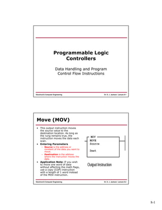
- 1. 8-1 Dr. D. J. Jackson Lecture 8-1Electrical & Computer Engineering Programmable Logic Controllers Data Handling and Program Control Flow Instructions Dr. D. J. Jackson Lecture 8-2Electrical & Computer Engineering Move (MOV) • This output instruction moves the source value to the destination location. As long as the rung remains true, the instruction moves the data each scan. • Entering Parameters – Source is the address or constant of the data you want to move. – Destination is the address where the instruction moves the data. • Application Note: If you wish to move one word of data without affecting the math flags, use a copy (COP) instruction with a length of 1 word instead of the MOV instruction.
- 2. 8-2 Dr. D. J. Jackson Lecture 8-3Electrical & Computer Engineering Using MOV for Variable Initialization • S:1/15 is a bit in the status date file that is energized for exactly one PLC scan when the PLC is placed in run mode • Can be used to condition the initialization of variables used elsewhere in the ladder logic Dr. D. J. Jackson Lecture 8-4Electrical & Computer Engineering Masked Move (MVM) • The MVM instruction is a word instruction that moves data from a source location to a destination, and allows portions of the destination data to be masked by a separate word. • As long as the rung remains true, the instruction moves the data each scan. • Entering Parameters – Source is the address of the data you want to move. – Mask is the address of the mask through which the instruction moves data; the mask can be a hexadecimal value (constant). – Destination is the address where the instruction moves the data.
- 3. 8-3 Dr. D. J. Jackson Lecture 8-5Electrical & Computer Engineering And (AND) • This instruction performs a bit-by-bit logical AND. The operation is performed using the value at source A and the value at source B. The result is stored in the destination. • Source A and B can either be a word address or a constant; however, both sources cannot be a constant. The destination must be a word address. • Application Note: When entering constants, you can use the ampersand (&) operator to change the radix of your entry. – Instead of entering –1 as a constant, you could enter &B1111111111111111 or &HFFFF (Actual PLC only) – Use 1111111111111111B or FFFFH for the simulator Dr. D. J. Jackson Lecture 8-6Electrical & Computer Engineering Or (OR), Xor (XOR), Not (NOT) OR, XOR, and NOT operands are exactly as described for the AND operation
- 4. 8-4 Dr. D. J. Jackson Lecture 8-7Electrical & Computer Engineering Clear (CLR) Instruction • Use the CLR instruction to set the destination value of a word to zero • This instruction always sets the Zero (Z) flag (S:0/2) • Other arithmetic status bits are always cleared (reset) – S:0/0, carry (C) – S:0/1, overflow (V) – S:0/3, sign (S) Dr. D. J. Jackson Lecture 8-8Electrical & Computer Engineering Program Flow Control Instructions Instruction Purpose Mnemonic Name JMP and LBL Jump to Label and Label Jump forward or backward to the specified label instruction JSR, SBR, and RET Jump to Subroutine, Subroutine and Return from Subroutine Jump to a designated subroutine and return MCR Master Control Reset Turn off all non-retentive outputs in a section of ladder program TND Temporary End Mark a temporary end that halts program execution SUS Suspend Identifies specific conditions for program debugging and system troubleshooting
- 5. 8-5 Dr. D. J. Jackson Lecture 8-9Electrical & Computer Engineering About the Program Flow Control Instructions • Use these instructions to control the sequence in which your program is executed. • Control instructions allow you to change the order in which the processor scans a ladder program. • Typically, these instructions are used to – minimize scan time, – create a more efficient program, – and troubleshoot a ladder program. Dr. D. J. Jackson Lecture 8-10Electrical & Computer Engineering Jump (JMP) and Label (LBL) If the rung containing the JMP instruction is: Then the Program: True Skips from the rung with the JMP to the rung containing the designated LBL False Does not execute the JMP • Use these instructions in pairs to skip portions of the ladder program – Jumping forward to a label saves program scan time by omitting a program segment until needed – Jumping backward lets the controller execute program segments repeatedly
- 6. 8-6 Dr. D. J. Jackson Lecture 8-11Electrical & Computer Engineering Jump (JMP) and Label (LBL) • Labels have the format Q:NNN. NNN is a numeric value from 000-255. • Jumping forward to a label saves program scan time by omitting a program segment until needed • Jumping backward lets the controller execute program segments repeatedly – Be careful not to jump backwards an excessive number of times – The watchdog timer could time out and fault the controller – Use a counter, timer, or the “program scan” register (system status register, word S:3, bits 0 to 7) to limit the amount of time you spend looping inside of JMP/LBL instructions Dr. D. J. Jackson Lecture 8-12Electrical & Computer Engineering JMP and LBL Example • Selectively jump over rung 1 if I:1/0 is energized. • In this example, O:2/1 would retain its last evaluated state if rung 1 is skipped • Use extreme caution in programming
- 7. 8-7 Dr. D. J. Jackson Lecture 8-13Electrical & Computer Engineering Using JMP and LBL • Using JMP – The JMP instruction causes the controller to skip rungs. You can jump to the same label from one or more JMP instruction. • Using LBL – This input instruction is the target of JMP instructions having the same label number. – You must program this instruction as the first instruction of a rung. This instruction has no control bits. – You can program multiple jumps to the same label by assigning the same label number to multiple JMP instructions. However, label numbers must be unique. • Note Do not jump (JMP) into an MCR zone. Instructions that are programmed within the MCR zone starting at the LBL instruction and ending at the ‘END MCR’ instruction are always evaluated as though the MCR zone is true, regardless of the true state of the “Start MCR” instruction. Dr. D. J. Jackson Lecture 8-14Electrical & Computer Engineering Jump to Subroutine (JSR), Subroutine (SBR), and Return (RET) • The JSR, SBR, and RET instructions are used to direct the controller to execute a separate subroutine file within the ladder program and return to the instruction following the JSR instruction.
- 8. 8-8 Dr. D. J. Jackson Lecture 8-15Electrical & Computer Engineering Subroutine Usage • If you use the SBR instruction, the SBR instruction must be the first instruction on the first rung in the program file that contains the subroutine. – Use a subroutine to store recurring sections of program logic that must be executed from several points within your application program – A subroutine saves memory because you program it only once. – Update critical I/O within subroutines using immediate input and/or output instructions (IIM, IOM), especially if your application calls for nested or relatively long subroutines – Otherwise, the controller does not update I/O until it reaches the end of the main program (after executing all subroutines) • Outputs controlled within a subroutine remain in their last state until the subroutine is executed again. Dr. D. J. Jackson Lecture 8-16Electrical & Computer Engineering JSR, SBR, and RET Usage • Using JSR – When the JSR instruction is executed, the controller jumps to the subroutine instruction (SBR) at the beginning of the target subroutine file and resumes execution at that point. – You cannot jump into any part of a subroutine except the first instruction in that file. • Using SBR – The target subroutine is identified by the file number that you entered in the JSR instruction. – This instruction serves as a label or identifier for a program file as a regular subroutine file. – The instruction must be programmed as the first instruction of the first rung of a subroutine. • Using RET – This output instruction marks the end of subroutine execution or the end of the subroutine file. – The rung containing the RET instruction may be conditional if this rung precedes the end of the subroutine. In this way, the controller omits the balance of a subroutine only if its rung condition is true.
- 9. 8-9 Dr. D. J. Jackson Lecture 8-17Electrical & Computer Engineering JSR, SBR, and RET Usage Dr. D. J. Jackson Lecture 8-18Electrical & Computer Engineering JSR, SBR, and RET Usage (short form)
- 10. 8-10 Dr. D. J. Jackson Lecture 8-19Electrical & Computer Engineering Master Control Reset (MCR) If the MCR Rung that starts the zone is: Then the Controller: True Executes the rungs in the MCR zone based on each rung’s individual input condition (as if the zone did not exist) False Resets all non-retentive output instructions in the MCR zone regardless of each rung’s individual input conditions Dr. D. J. Jackson Lecture 8-20Electrical & Computer Engineering Master Control Reset (MCR) • MCR zones let you enable or inhibit segments of your program, such as for recipe applications • When you program MCR instructions, note that: – You must end the zone with an unconditional MCR instruction. – You cannot nest one MCR zone within another. – Do not jump into an MCR zone. If the zone is false, jumping into it activates the zone. – Always place the MCR instruction as the last instruction in a rung. • Use MCR instructions in pairs to create program zones that turn off all the non-retentive outputs in the zone – Rungs within the MCR zone are still scanned, but scan time is reduced due to the false state of non-retentive outputs
- 11. 8-11 Dr. D. J. Jackson Lecture 8-21Electrical & Computer Engineering MCR Usage • The MCR instruction is not a substitute for a hard–wired master control relay that provides emergency stop capability. – You should still install a hard–wired master control relay to provide emergency I/O power shutdown. • Do not jump (JMP) into an MCR zone. – Instructions that are programmed within the MCR zone starting at the LBL instruction and ending at the ‘END MCR’ instruction are always evaluated as though the MCR zone is true, regardless of the true state of the “Start MCR” instruction. If the zone is false, jumping into it activates the zone from the LBL to the end of the zone. • If you start instructions such as timers or counters in an MCR zone, instruction operation ceases when the zone is disabled. – Re-program critical operations outside the zone if necessary. • The TOF timer activates when placed inside of a false MCR zone. Dr. D. J. Jackson Lecture 8-22Electrical & Computer Engineering Temporary End (TND) • This instruction, when its rung is true: – Stops the processor from scanning the rest of the program file – Updates the I/O, and – Resumes scanning at rung 0 of the main program (file 2) • If this instruction’s rung is false, the processor continues the scan until the next TND instruction or the END statement • Use this instruction to progressively debug a program, or conditionally omit the balance of your current program file or subroutines
- 12. 8-12 Dr. D. J. Jackson Lecture 8-23Electrical & Computer Engineering Suspend (SUS) • When this instruction is executed, it causes the processor to enter the Suspend Idle mode and stores the Suspend ID in word 7 (S:7) of the status file. • All outputs are de- energized. • Use this instruction to trap and identify specific conditions for program debugging and system troubleshooting.