
Recommended
More Related Content
What's hot
What's hot (20)
Viewers also liked
Viewers also liked (17)
Similar to Programmable Logic Controllers: VisiLogic Overview and Basic Ladder Logic
Similar to Programmable Logic Controllers: VisiLogic Overview and Basic Ladder Logic (20)
Recently uploaded
Recently uploaded (20)
Programmable Logic Controllers: VisiLogic Overview and Basic Ladder Logic
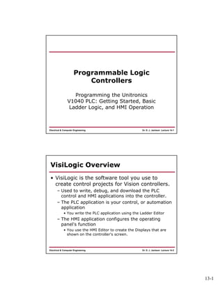
- 1. 13-1 Dr. D. J. Jackson Lecture 14-1Electrical & Computer Engineering Programmable Logic Controllers Programming the Unitronics V1040 PLC: Getting Started, Basic Ladder Logic, and HMI Operation Dr. D. J. Jackson Lecture 14-2Electrical & Computer Engineering VisiLogic Overview • VisiLogic is the software tool you use to create control projects for Vision controllers. – Used to write, debug, and download the PLC control and HMI applications into the controller. – The PLC application is your control, or automation application • You write the PLC application using the Ladder Editor – The HMI application configures the operating panel's function • You use the HMI Editor to create the Displays that are shown on the controller's screen.
- 2. 13-2 Dr. D. J. Jackson Lecture 14-3Electrical & Computer Engineering HMI Displays • Displays tell your operators what to do – Provides status information about the system – Links to ladder logic being solved by the PLC • You can have your operators enter data, and have the display instruct the operator what to do in case of a system problem or alarm • A Display can contain both text and images – Text and images can be both fixed and/or variable Dr. D. J. Jackson Lecture 14-4Electrical & Computer Engineering HMI Variables • Variables are inserted into a Display to: – Show run-time values as integers – Represent run-time values with either text, images, or bar graphs – Show text messages that vary according to runtime conditions – Enable an operator to enter data using the Vision's alphanumeric keypad
- 3. 13-3 Dr. D. J. Jackson Lecture 14-5Electrical & Computer Engineering VisiLogic Editors • You use different editors to create your control project: – Hardware Configuration – Ladder – HMI Display – Variable • Hardware Configuration • Define PLC type, communication, I/O modules, etc. • Similar concept to Allen Bradley hardware configuration • Ladder Editor • Used to create the Ladder diagram that comprises your control application • Ladder diagrams are composed of contacts, coils, and function block elements arranged in nets Dr. D. J. Jackson Lecture 14-6Electrical & Computer Engineering VisiLogic Software Layout
- 4. 13-4 Dr. D. J. Jackson Lecture 14-7Electrical & Computer Engineering Hardware Configuration • Select V1040 PLC type Dr. D. J. Jackson Lecture 14-8Electrical & Computer Engineering Hardware Configuration • Use “Connection -> Communication & OS” to define connection between PC and PLC. • PC Port may vary
- 5. 13-5 Dr. D. J. Jackson Lecture 14-9Electrical & Computer Engineering Ladder Editor • In a Ladder diagram, the contacts represent input conditions – They lead power from the left Ladder rail to the right rail – This is why the first element in a net must always touch the left rail • Coils represent output instructions. In order for output coils to be activated, the logical state of the contacts must allow the power to flow through the net to the coil – This is why the elements in a net must be connected – Each net must contain only one rung Dr. D. J. Jackson Lecture 14-10Electrical & Computer Engineering Ladder Editor • Use the Ladder Editor to: – Place and connect Ladder Elements – Apply Compare, Math, Logic, Clock, Store, and Vector functions – Insert Function Blocks (FBs) into your program – Build program Modules and Subroutines, and use internal Subroutine Jumps and Labels – Place Comments on Ladder nets • Ladder elements and functions may be dragged and dropped between nets
- 6. 13-6 Dr. D. J. Jackson Lecture 14-11Electrical & Computer Engineering Basic Ladder Logic Example Dr. D. J. Jackson Lecture 14-12Electrical & Computer Engineering Operand Types • We will use the following operand types in our initial examples – MB – Memory Bit – MI – Memory Integer (16-bit) – ML – Memory Long (32-bit) – T – Timer (32-bit) – C – Counter (16-bit) • Other operand types will be introduced as needed
- 7. 13-7 Dr. D. J. Jackson Lecture 14-13Electrical & Computer Engineering Basic Ladder Elements - Contacts • Direct Contact -- a normally open (NO) contact • Inverted Contact -- a normally closed (NC) contact • Positive Transition Contact (Rise) – A one shot pulse when the referenced bit changes from 0->1 • Negative Transition Contact (Fall) – A one shot pulse when the referenced bit changes from 1->0 Dr. D. J. Jackson Lecture 14-14Electrical & Computer Engineering Basic Ladder Elements - Coils • Direct Coil -- turns ON when the preceding net conditions are ON • Inverted Coil -- turns OFF when the preceding net conditions are ON • Set Coil -- turns a set coil ON(latches), when preceding net conditions are ON • Reset Coil -- turns a set coil OFF (unlatches), when preceding net conditions are ON • Toggle Coil -- changes its state when it is activated
- 8. 13-8 Dr. D. J. Jackson Lecture 14-15Electrical & Computer Engineering Simple Ladder Logic Program Dr. D. J. Jackson Lecture 14-16Electrical & Computer Engineering HMI Editor • Insert shapes, buttons and images onto the display and associate them with specific elements (operands) from the ladder logic program