


![Sharp-crested weir with rectangular cross section
12
Problems
10.12 Water passes over a rectangular weir of 10 ft width at a depth of 1 ft. If the weir
is replaced by an 80° V-notch, determine the depth of water over the notch.
Disregard the end contractions. Cd for notch = 0.59, Cd for rectangular weir =
0.63.
10.16 A submerged weir in a pond is 10 ft long. The crest of the weir is 9 in. below
the upstream level and 6 in. below the tailwater level. The crest height is 1 ft.
Determine the discharge.
10.17 A stream is 200 ft wide and 10 ft deep. It has a mean velocity of flow of 4
ft/sec. If a submerged weir of 8 ft height is installed, how much will the water
upstream rise? Disregard the velocity approach. [Hint: Assume Cd, determine H1
for the submerged case, calculate revised Cd from the formula, and find revised
H1.]](https://image.slidesharecdn.com/weirsandflumeslayheangwithbroad1-161130114705/75/Weirs-and-flumes-with-broad-12-2048.jpg)


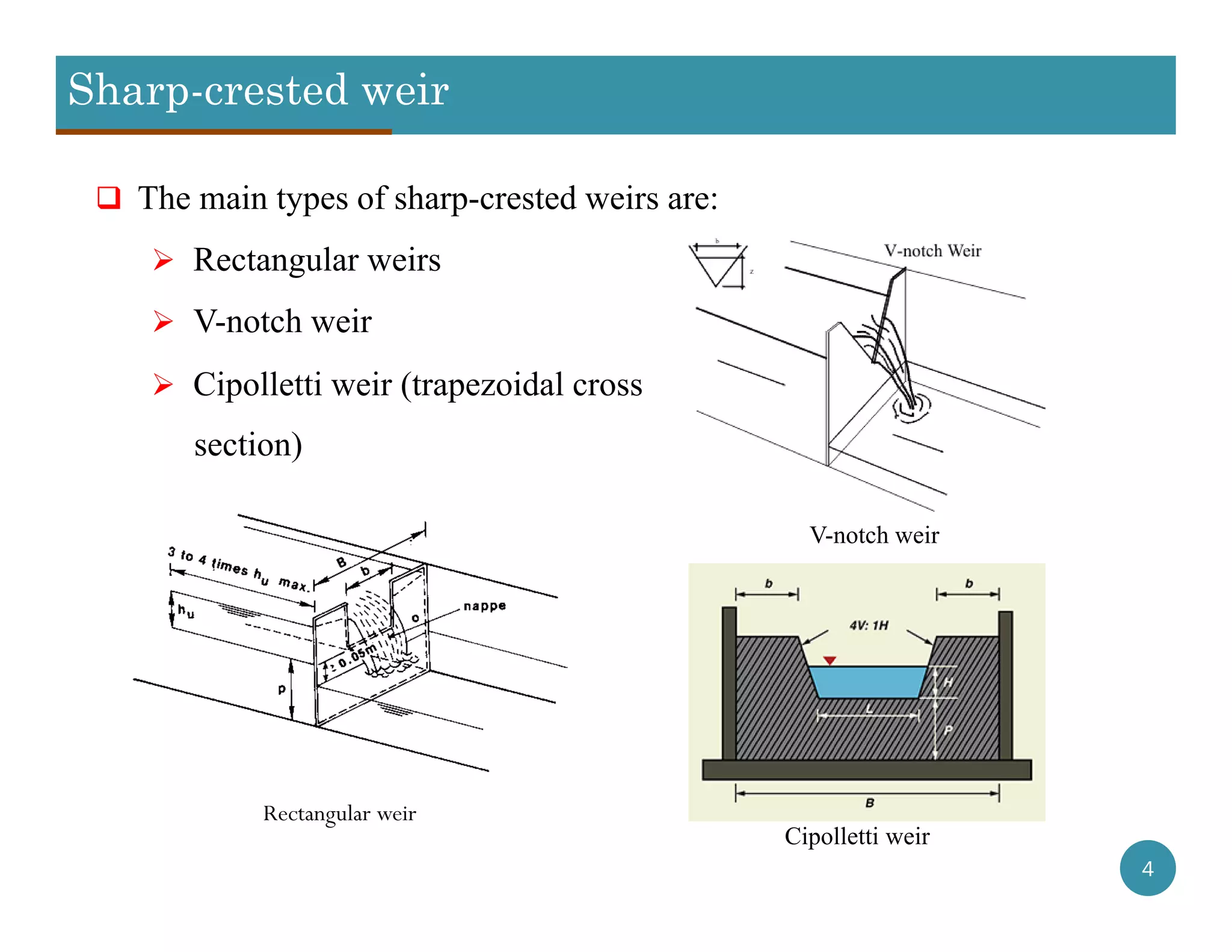
This document provides information about weirs and Parshall flumes. It discusses different types of weirs including sharp-crested weirs like rectangular and V-notch weirs, as well as broad-crested weirs. Formulas are provided for calculating flow rates over these structures. The document also introduces the Parshall flume, which can be used as an alternative to weirs for measuring flow rates while reducing head losses and sediment accumulation. Key features of the Parshall flume design and measurement principles are described.


![Geotechnical Engineering-I [Lec #9: Atterberg limits]](https://cdn.slidesharecdn.com/ss_thumbnails/9-180923180923-thumbnail.jpg?width=640&height=640&fit=bounds)