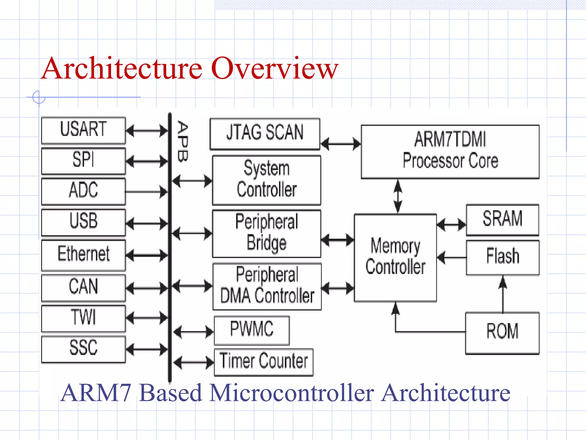
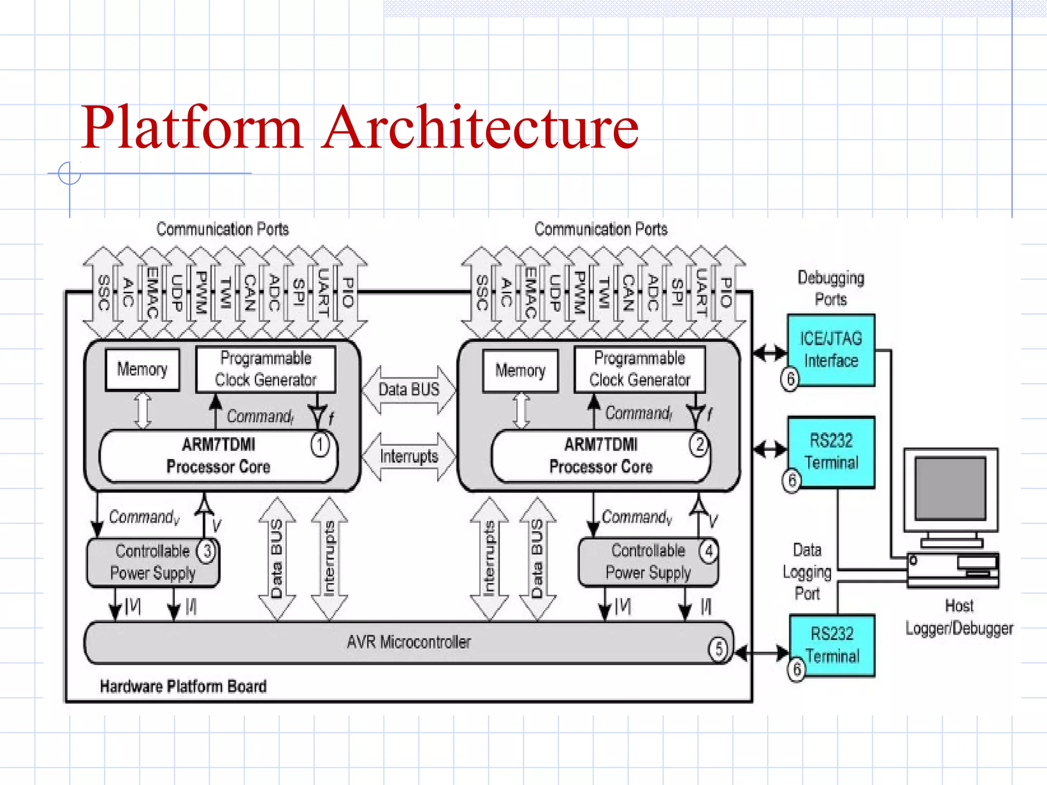
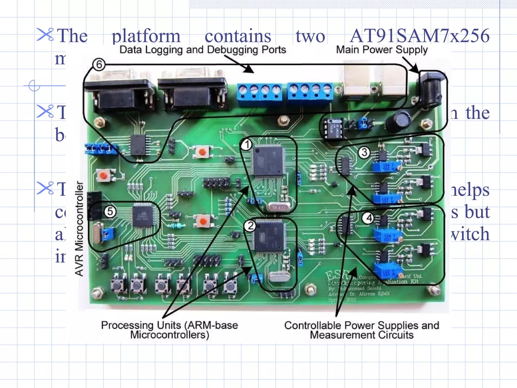
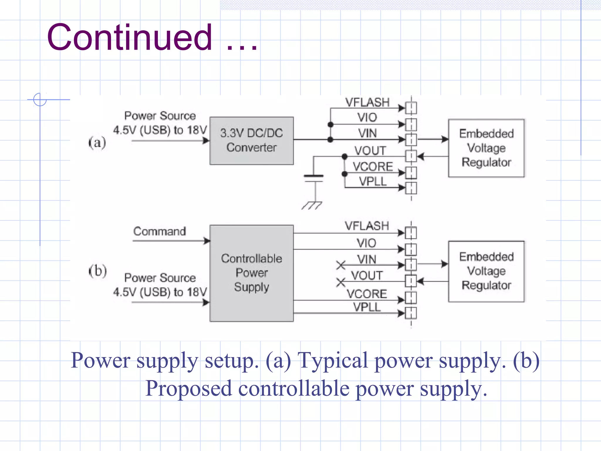
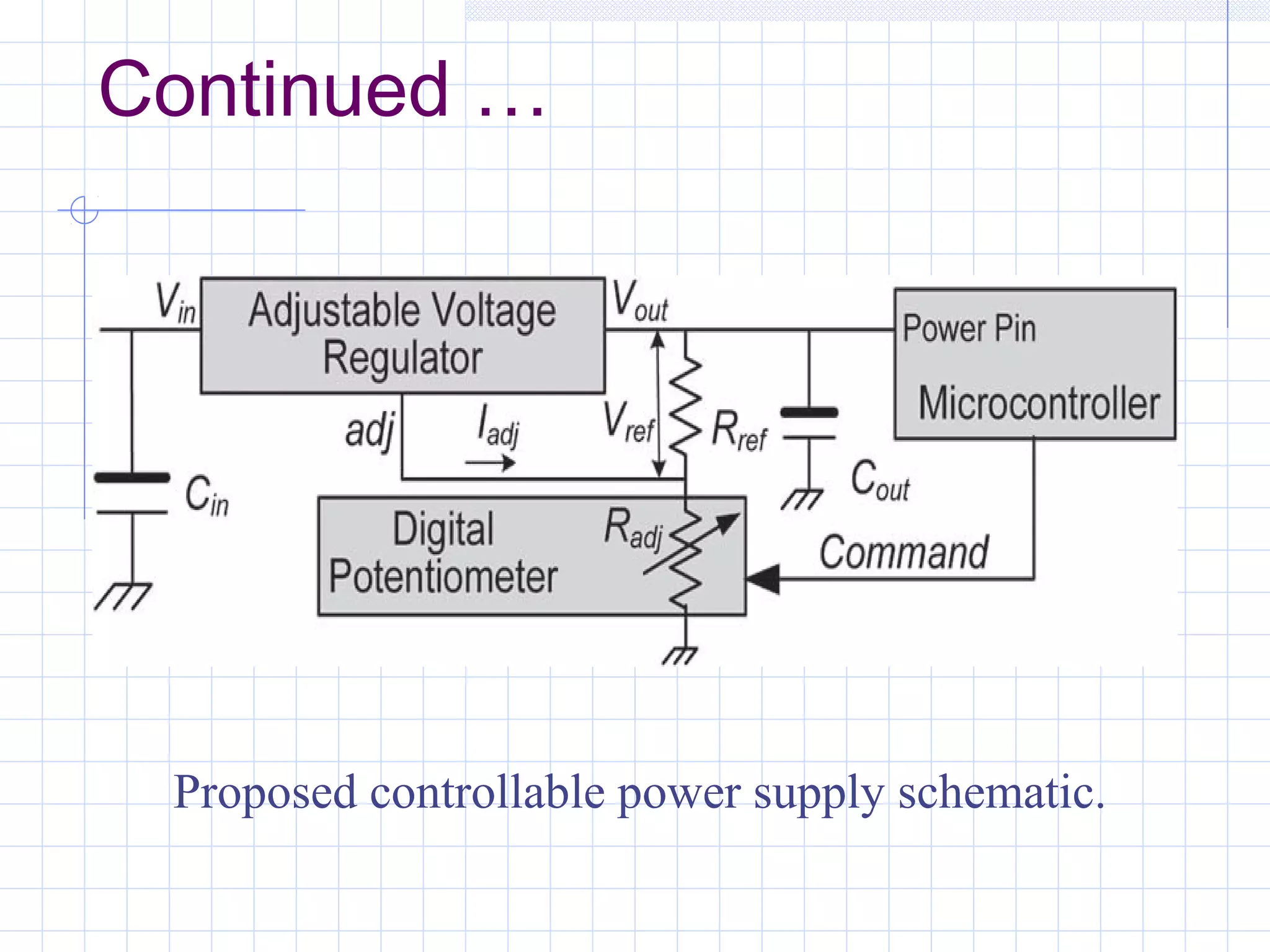
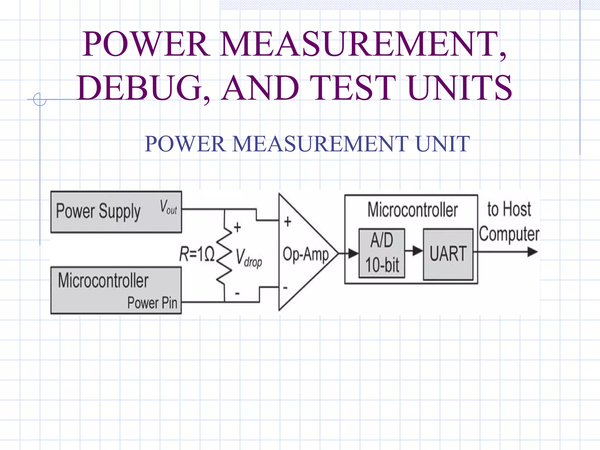
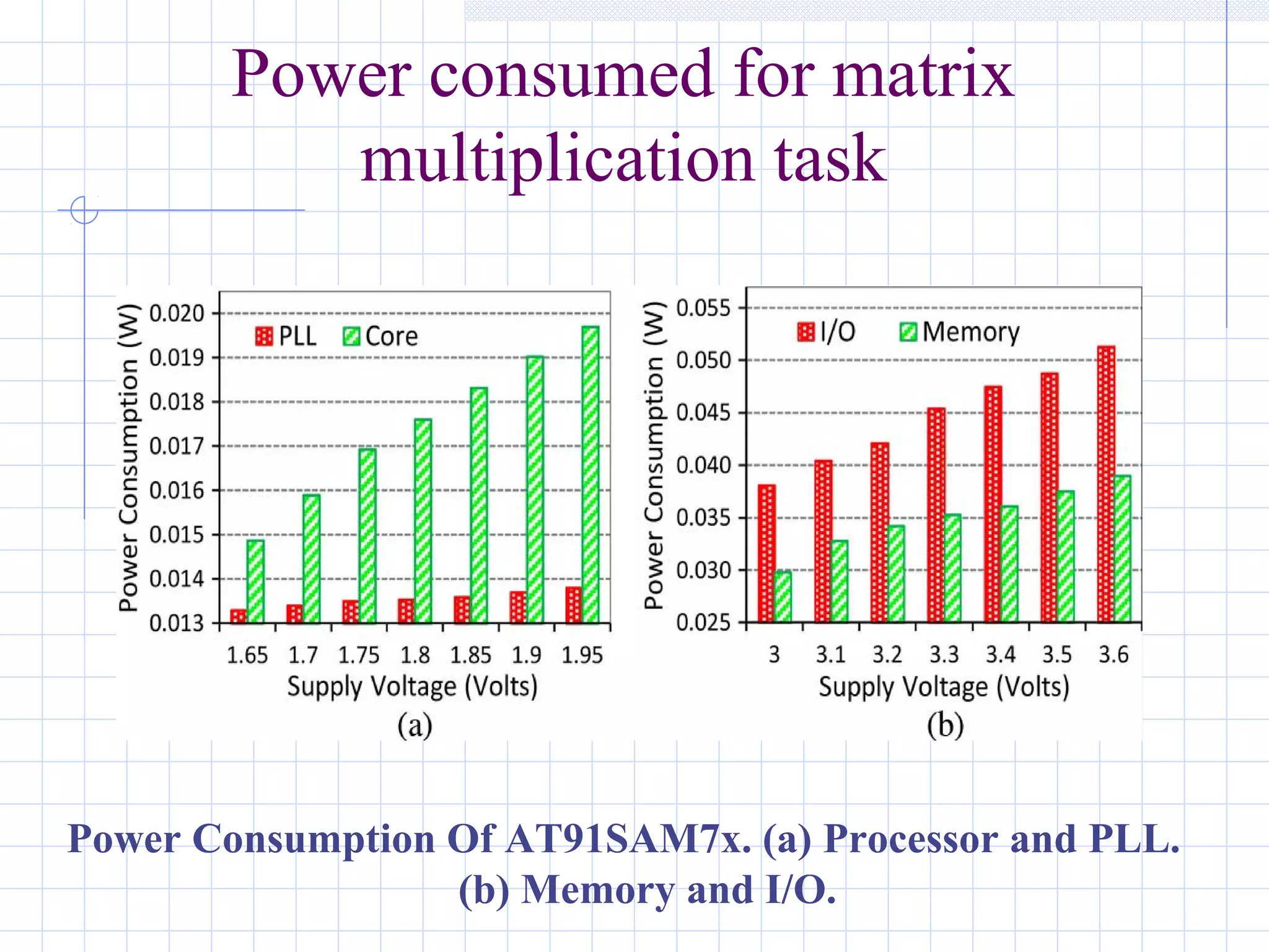
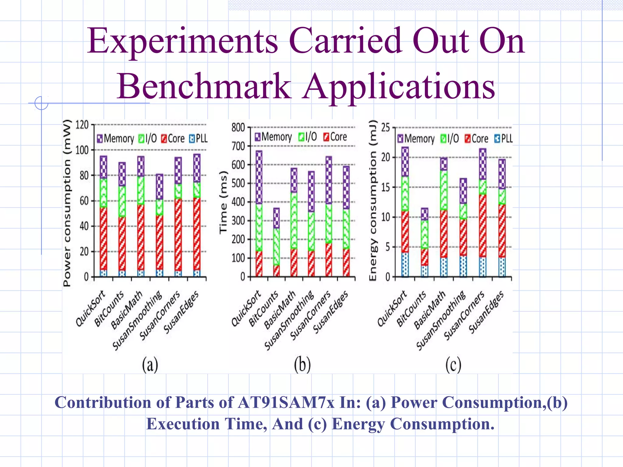
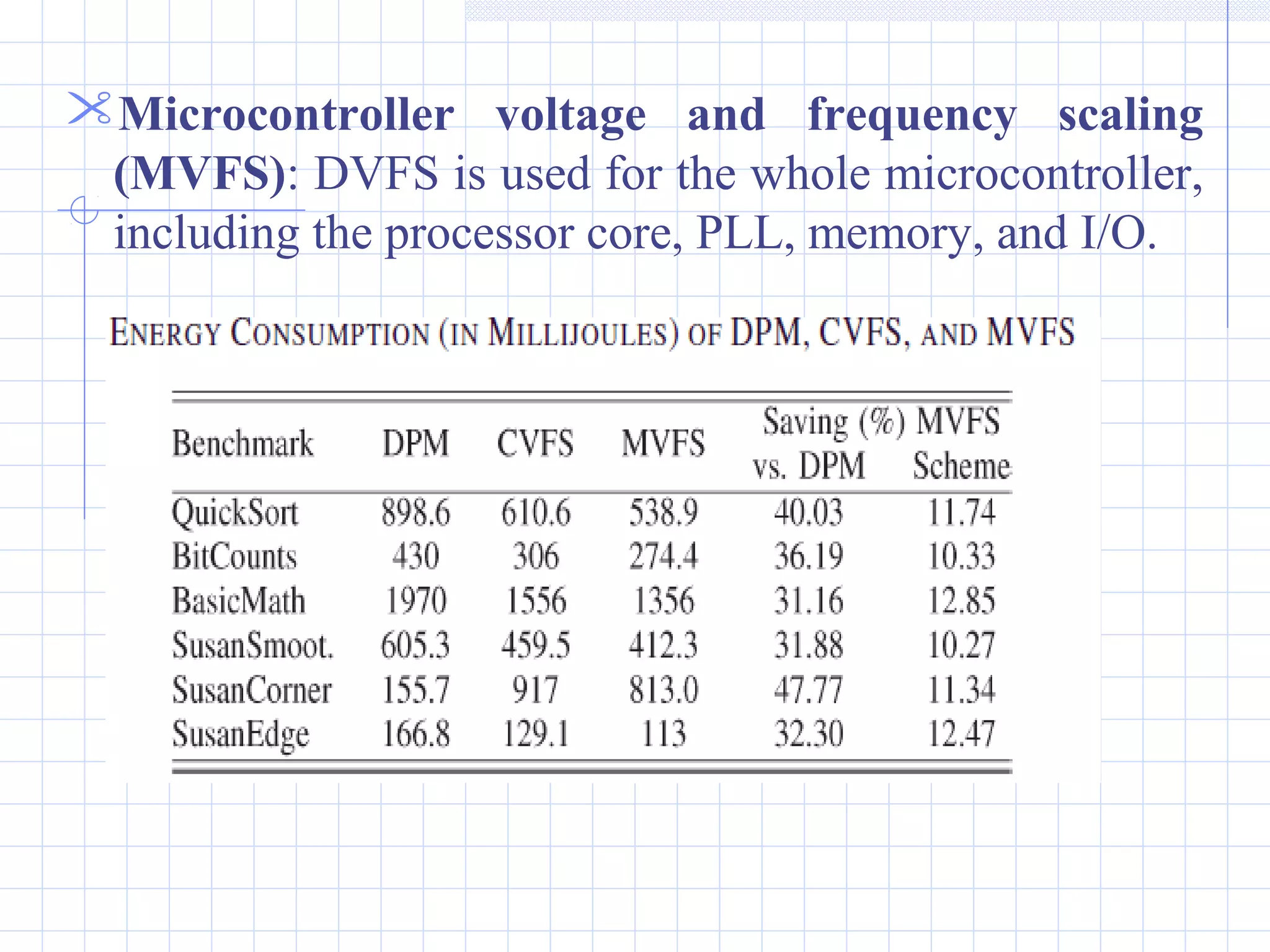
A Hardware Platform For Evaluating Low-
energy Multiprocessor Embedded Systems
Based On COTS Devices
Presented by: Syeda Nasiha
Contents
 Introduction
 Features Of Proposed Work
 Hardware Platform Architecture
 Architecture of Arm7 based microcontroller
 Architecture of proposed platform
 Energy Management Units
 Dynamic Power Management(DPM)
 Dynamic Voltage And Frequency Scaling(DVFS)
 Power Measurement, Debug And Test Units
 Experimental Results
 Energy Management Techniques
 Extension And Future Work
 Conclusion
INTRODUCTION
 A wide range of embedded systems are battery
operated
The use of COTS devices is very beneficial in
designing embedded systems
A hardware platform based on ARM COTS
processor is proposed for experimenting with
energy management techniques
FEATURES OF PROPOSED
WORK
Provides DVFS capability to processor cores and
also to PLL, memory and I/O.
Includes circuitry to separately measure energy
and power consumption of different parts.
Platform is suitable for research into energy
management techniques in parallel processing.
HARDWARE PLATFORM
DESIGN
ARM7TDMI-based COTS processor is used.
Its computational power is quite sufficient for
majority of embedded applications.
For highly computation-intensive applications, the
performance might not be adequate.
Architecture Overview
ARM7 Based Microcontroller Architecture
Platform Architecture
The platform contains two AT91SAM7x256
microcontrollers connected via a bus.
Two controllable power supplies are included in the
board
The use of separate supply voltages not only helps
conduct experiments with various DVFS schemes but
also can be used to shut off one processor to switch
into a single-processor configuration
ENERGY MANAGEMENT
UNITS
DVFS varies the components’ voltage and, hence,
frequency based on the system workload.
DPM selectively turns off the system components
when they are idle.
DPM
Power management unit. (a) Clock generator. (b) Power
management controller
Continued …
DVFS
The active power consumption of a clock-enabled
component can be determined by its operating
frequency and supply voltage, as denoted by
PActive = ILeakageV+ CeffV2
f
Frequency scaling reduces the dynamic power
consumption linearly, it has no effect on the static
leakage power consumption.
Continued …
Voltage scaling techniques employ adjustable voltage
regulators to set the supply voltage of the processor
core and clock-enabled components.
The basic idea behind DVFS techniques is to
determine the minimum frequency that satisfies all
timing constraints and then to adjust the lowest
possible voltage that allows this speed
The AT91SAM7x microcontrollers have six power
supply pins and a built-in voltage regulator, allowing
the device to support a 3.3-V single-supply mode.
Continued …
Power supply setup. (a) Typical power supply. (b)
Proposed controllable power supply.
Continued …
Proposed controllable power supply schematic.
Continued ..
The adjustable voltage regulator can provide an
output voltage from 1.25 to 13.8 V with exploiting
two external resistors(Rref and Radj)
1.25v reference voltage is applied across the resistor
Rref to produce a constant current that flows through
the adjustment resistor Radj and fixes the output
voltage Vout to the desired level as
Vout = VREF(1+Radj/Rref) + IadjRadj
POWER MEASUREMENT,
DEBUG, AND TEST UNITS
POWER MEASUREMENT UNIT
DEBUG UNIT
EXPERIMENTAL RESULTS
 LPC11U6x series provide four power modes, namely, Sleep, Deep-sleep,
Power-down, and Deep power-down modes
 PXA270 provides Turbo mode, Run mode, Idle and Deep-idle modes,
Standby mode, Sleep mode, and Deep-sleep.
In the experiments, the processor and PLL voltages could be
any value from the set {1.65, 1.7, 1.75, 1.8, 1.85, 1.9, and
1.95 V} and I/O and memory voltages could be any value
from the set {3.0, 3.1, 3.2,3.3, 3.4, 3.5, and 3.6 V}
A set of different frequency levels corresponding to different
voltage levels are available
Experimental Setup and Monitoring. (a) Setup. (b) Voltage of I/O. (c)
Voltage of the Processor.
Analyzing voltage scaling delay
 H-to-L voltage scaling delay is 118 and 34 micro secs for I/O and
processor respectively
 L-to-H voltage scaling delay is 55 and 23 micro secs for I/O and processor
respectively
High-To-Low And Low-To-High Voltage Scaling Delays. (a) I/O
(b) Processor
Power consumed for matrix
multiplication task
Power Consumption Of AT91SAM7x. (a) Processor and PLL.
(b) Memory and I/O.
Experiments Carried Out On
Benchmark Applications
Contribution of Parts of AT91SAM7x In: (a) Power Consumption,(b)
Execution Time, And (c) Energy Consumption.
The high-to-low voltage scaling delay is greater than
the low-to-high delay
PLL, memory, and I/O have less power consumption
but comparable energy consumption to that of the
processor core.
As PLL is always operational its energy consumption
is comparable with other components
Continued…
Energy Management Techniques
DPM: When there is an idle time, the microcontroller
enters the low-power mode, i.e, memory is standby,
processor core is idle, main clock = 500 Hz, and all
peripheral clocks are deactivated.
Core voltage and frequency scaling (CVFS):The
processor frequency is set to the slowest frequency
(and its corresponding voltage) necessary to finish the
application.
Microcontroller voltage and frequency scaling
(MVFS): DVFS is used for the whole microcontroller,
including the processor core, PLL, memory, and I/O.
Extensions And Future Work
The two microcontrollers are connected such that they can
interrupt, restart, and turn on/off each other.
 Each of the microcontrollers can access the internal parts of
the other via JTAG.
There are interconnections to transfer data, internal states, and
checkpoints between the microcontrollers.
A third smaller microcontroller is placed in the platform that
can be used to implement fault-tolerance techniques.
Another possible extension is to adopt motherboard-
daughterboard architecture for design of the board to be used
for other microcontrollers
CONCLUSION
This paper has presented a hardware platform that
consists of two ARM-based microcontrollers, each
fed separately by variable voltages.
In this platform, DVFS capability for the whole
microcontroller has been provided.
Continued …
The platform is equipped with accurate
energy/power measurement units, debugging
ports, and facilities for evaluating fault-tolerance
techniques.
Although the platform is designed for ARM-based
microcontrollers, it is general, and other COTS
devices and embedded processors can be similarly
used in the design of the platform.
THANK YOU

Arm7 architecture

  • 1.
    A Hardware PlatformFor Evaluating Low- energy Multiprocessor Embedded Systems Based On COTS Devices Presented by: Syeda Nasiha
  • 2.
    Contents  Introduction  FeaturesOf Proposed Work  Hardware Platform Architecture  Architecture of Arm7 based microcontroller  Architecture of proposed platform  Energy Management Units  Dynamic Power Management(DPM)  Dynamic Voltage And Frequency Scaling(DVFS)  Power Measurement, Debug And Test Units  Experimental Results  Energy Management Techniques  Extension And Future Work  Conclusion
  • 3.
    INTRODUCTION  A widerange of embedded systems are battery operated The use of COTS devices is very beneficial in designing embedded systems A hardware platform based on ARM COTS processor is proposed for experimenting with energy management techniques
  • 4.
    FEATURES OF PROPOSED WORK ProvidesDVFS capability to processor cores and also to PLL, memory and I/O. Includes circuitry to separately measure energy and power consumption of different parts. Platform is suitable for research into energy management techniques in parallel processing.
  • 5.
    HARDWARE PLATFORM DESIGN ARM7TDMI-based COTSprocessor is used. Its computational power is quite sufficient for majority of embedded applications. For highly computation-intensive applications, the performance might not be adequate.
  • 6.
    Architecture Overview ARM7 BasedMicrocontroller Architecture
  • 7.
  • 8.
    The platform containstwo AT91SAM7x256 microcontrollers connected via a bus. Two controllable power supplies are included in the board The use of separate supply voltages not only helps conduct experiments with various DVFS schemes but also can be used to shut off one processor to switch into a single-processor configuration
  • 9.
    ENERGY MANAGEMENT UNITS DVFS variesthe components’ voltage and, hence, frequency based on the system workload. DPM selectively turns off the system components when they are idle.
  • 10.
    DPM Power management unit.(a) Clock generator. (b) Power management controller
  • 11.
  • 12.
    DVFS The active powerconsumption of a clock-enabled component can be determined by its operating frequency and supply voltage, as denoted by PActive = ILeakageV+ CeffV2 f Frequency scaling reduces the dynamic power consumption linearly, it has no effect on the static leakage power consumption.
  • 13.
    Continued … Voltage scalingtechniques employ adjustable voltage regulators to set the supply voltage of the processor core and clock-enabled components. The basic idea behind DVFS techniques is to determine the minimum frequency that satisfies all timing constraints and then to adjust the lowest possible voltage that allows this speed
  • 14.
    The AT91SAM7x microcontrollershave six power supply pins and a built-in voltage regulator, allowing the device to support a 3.3-V single-supply mode.
  • 15.
    Continued … Power supplysetup. (a) Typical power supply. (b) Proposed controllable power supply.
  • 16.
    Continued … Proposed controllablepower supply schematic.
  • 17.
    Continued .. The adjustablevoltage regulator can provide an output voltage from 1.25 to 13.8 V with exploiting two external resistors(Rref and Radj) 1.25v reference voltage is applied across the resistor Rref to produce a constant current that flows through the adjustment resistor Radj and fixes the output voltage Vout to the desired level as Vout = VREF(1+Radj/Rref) + IadjRadj
  • 18.
    POWER MEASUREMENT, DEBUG, ANDTEST UNITS POWER MEASUREMENT UNIT
  • 19.
  • 20.
    EXPERIMENTAL RESULTS  LPC11U6xseries provide four power modes, namely, Sleep, Deep-sleep, Power-down, and Deep power-down modes  PXA270 provides Turbo mode, Run mode, Idle and Deep-idle modes, Standby mode, Sleep mode, and Deep-sleep.
  • 21.
    In the experiments,the processor and PLL voltages could be any value from the set {1.65, 1.7, 1.75, 1.8, 1.85, 1.9, and 1.95 V} and I/O and memory voltages could be any value from the set {3.0, 3.1, 3.2,3.3, 3.4, 3.5, and 3.6 V} A set of different frequency levels corresponding to different voltage levels are available Experimental Setup and Monitoring. (a) Setup. (b) Voltage of I/O. (c) Voltage of the Processor.
  • 22.
    Analyzing voltage scalingdelay  H-to-L voltage scaling delay is 118 and 34 micro secs for I/O and processor respectively  L-to-H voltage scaling delay is 55 and 23 micro secs for I/O and processor respectively High-To-Low And Low-To-High Voltage Scaling Delays. (a) I/O (b) Processor
  • 23.
    Power consumed formatrix multiplication task Power Consumption Of AT91SAM7x. (a) Processor and PLL. (b) Memory and I/O.
  • 24.
    Experiments Carried OutOn Benchmark Applications Contribution of Parts of AT91SAM7x In: (a) Power Consumption,(b) Execution Time, And (c) Energy Consumption.
  • 25.
    The high-to-low voltagescaling delay is greater than the low-to-high delay PLL, memory, and I/O have less power consumption but comparable energy consumption to that of the processor core. As PLL is always operational its energy consumption is comparable with other components Continued…
  • 26.
    Energy Management Techniques DPM:When there is an idle time, the microcontroller enters the low-power mode, i.e, memory is standby, processor core is idle, main clock = 500 Hz, and all peripheral clocks are deactivated. Core voltage and frequency scaling (CVFS):The processor frequency is set to the slowest frequency (and its corresponding voltage) necessary to finish the application.
  • 27.
    Microcontroller voltage andfrequency scaling (MVFS): DVFS is used for the whole microcontroller, including the processor core, PLL, memory, and I/O.
  • 28.
    Extensions And FutureWork The two microcontrollers are connected such that they can interrupt, restart, and turn on/off each other.  Each of the microcontrollers can access the internal parts of the other via JTAG. There are interconnections to transfer data, internal states, and checkpoints between the microcontrollers. A third smaller microcontroller is placed in the platform that can be used to implement fault-tolerance techniques. Another possible extension is to adopt motherboard- daughterboard architecture for design of the board to be used for other microcontrollers
  • 29.
    CONCLUSION This paper haspresented a hardware platform that consists of two ARM-based microcontrollers, each fed separately by variable voltages. In this platform, DVFS capability for the whole microcontroller has been provided.
  • 30.
    Continued … The platformis equipped with accurate energy/power measurement units, debugging ports, and facilities for evaluating fault-tolerance techniques. Although the platform is designed for ARM-based microcontrollers, it is general, and other COTS devices and embedded processors can be similarly used in the design of the platform.
  • 31.