Downloaded 1,989 times
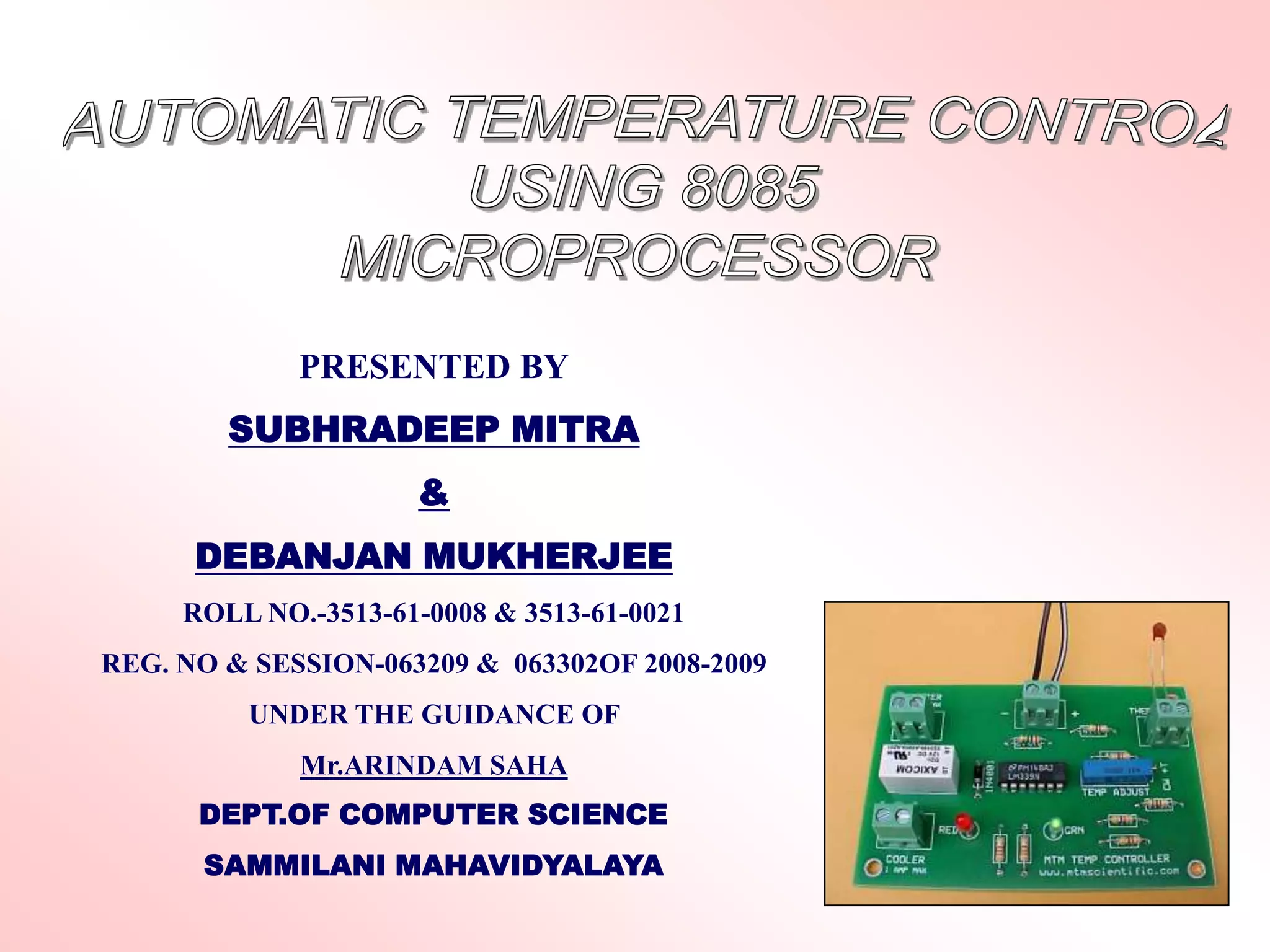
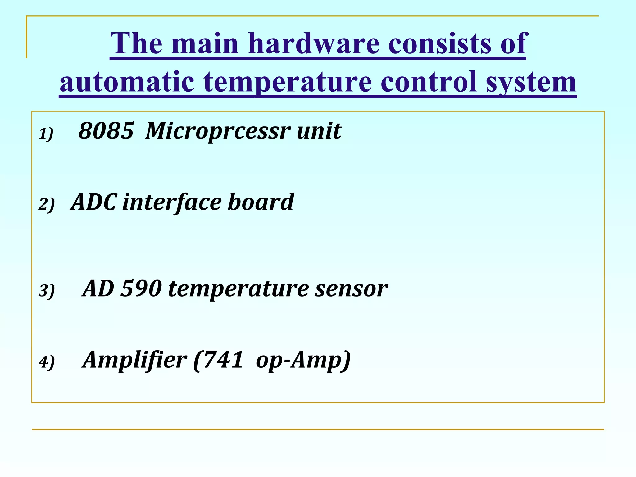
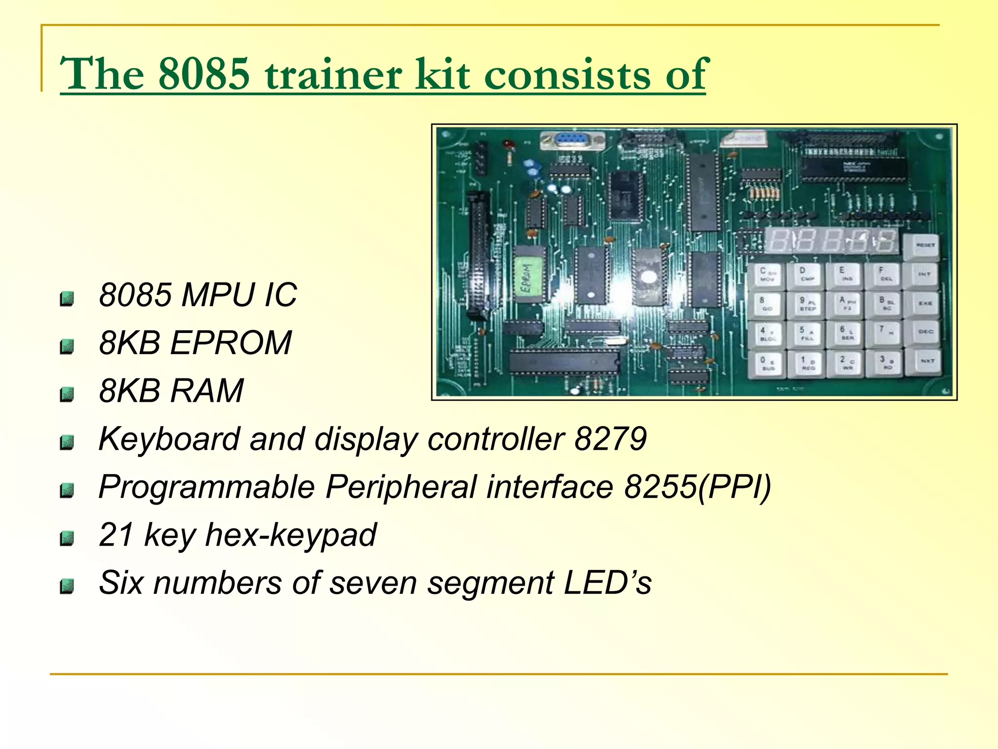
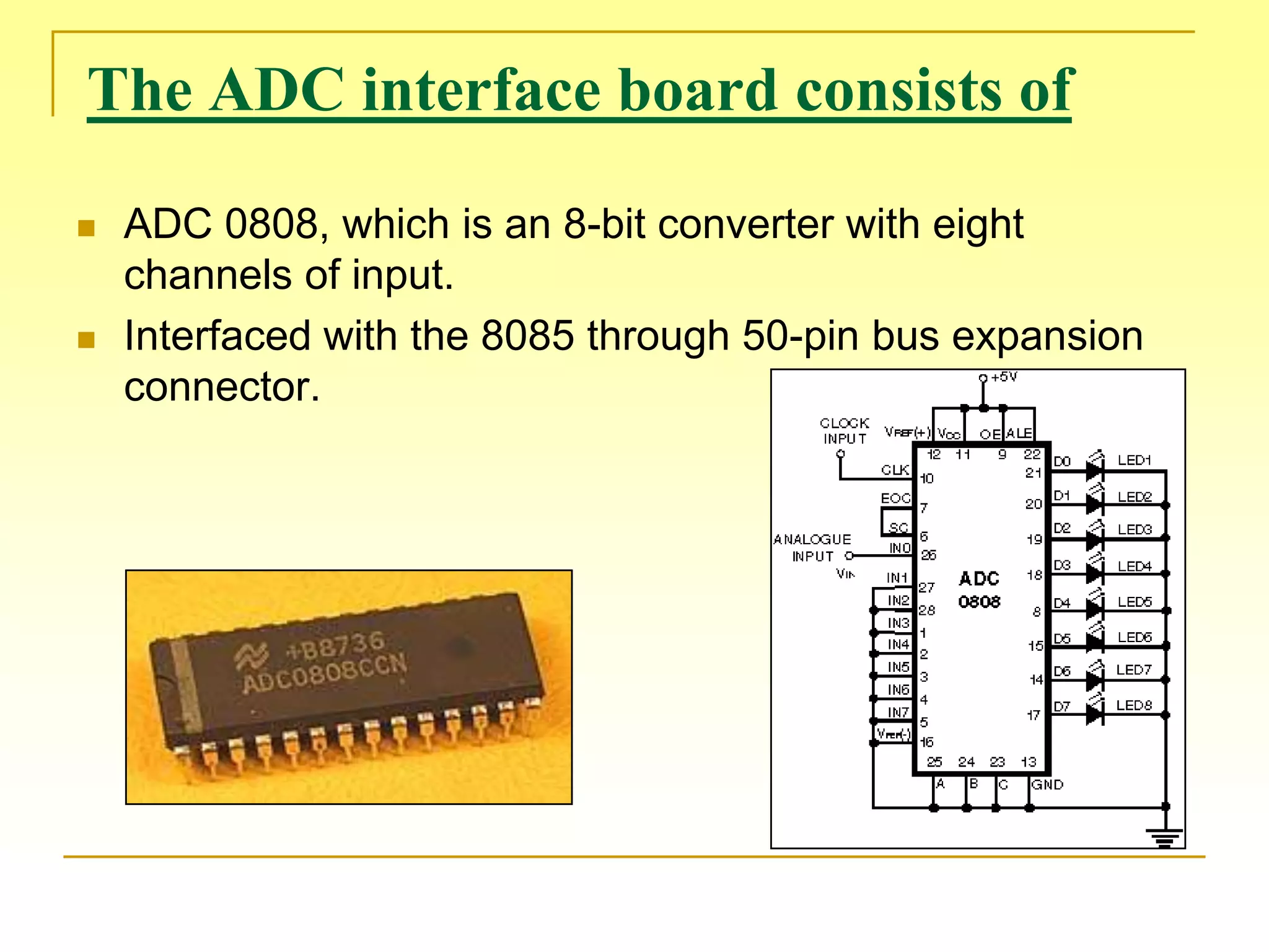
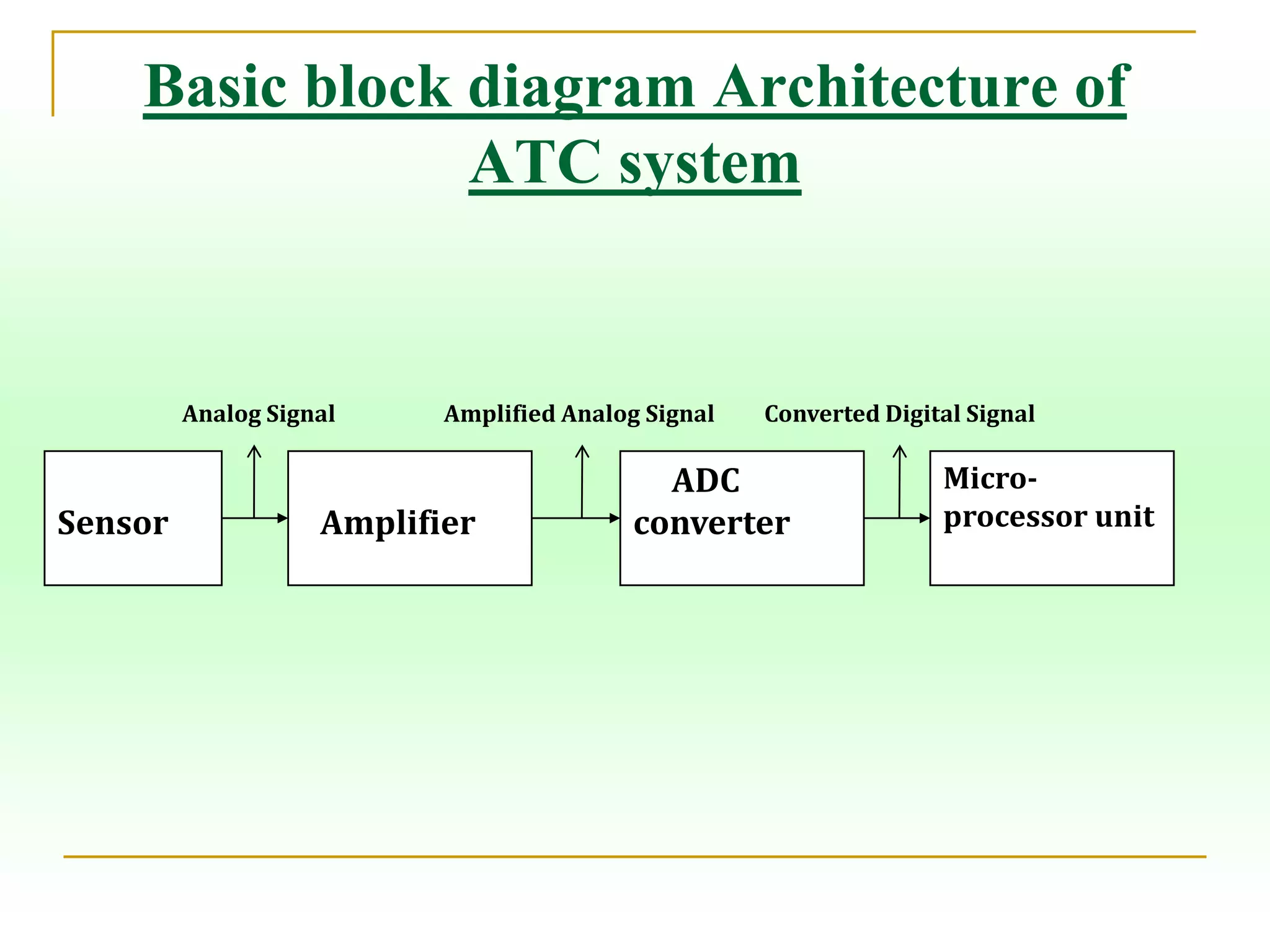
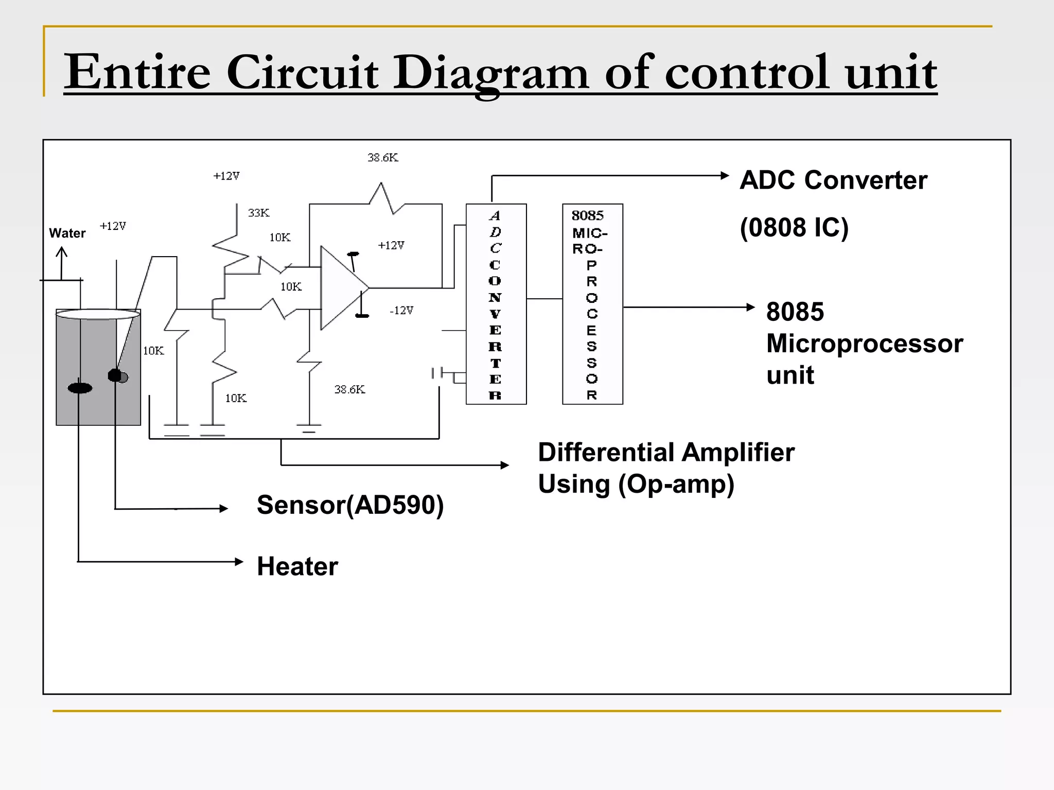

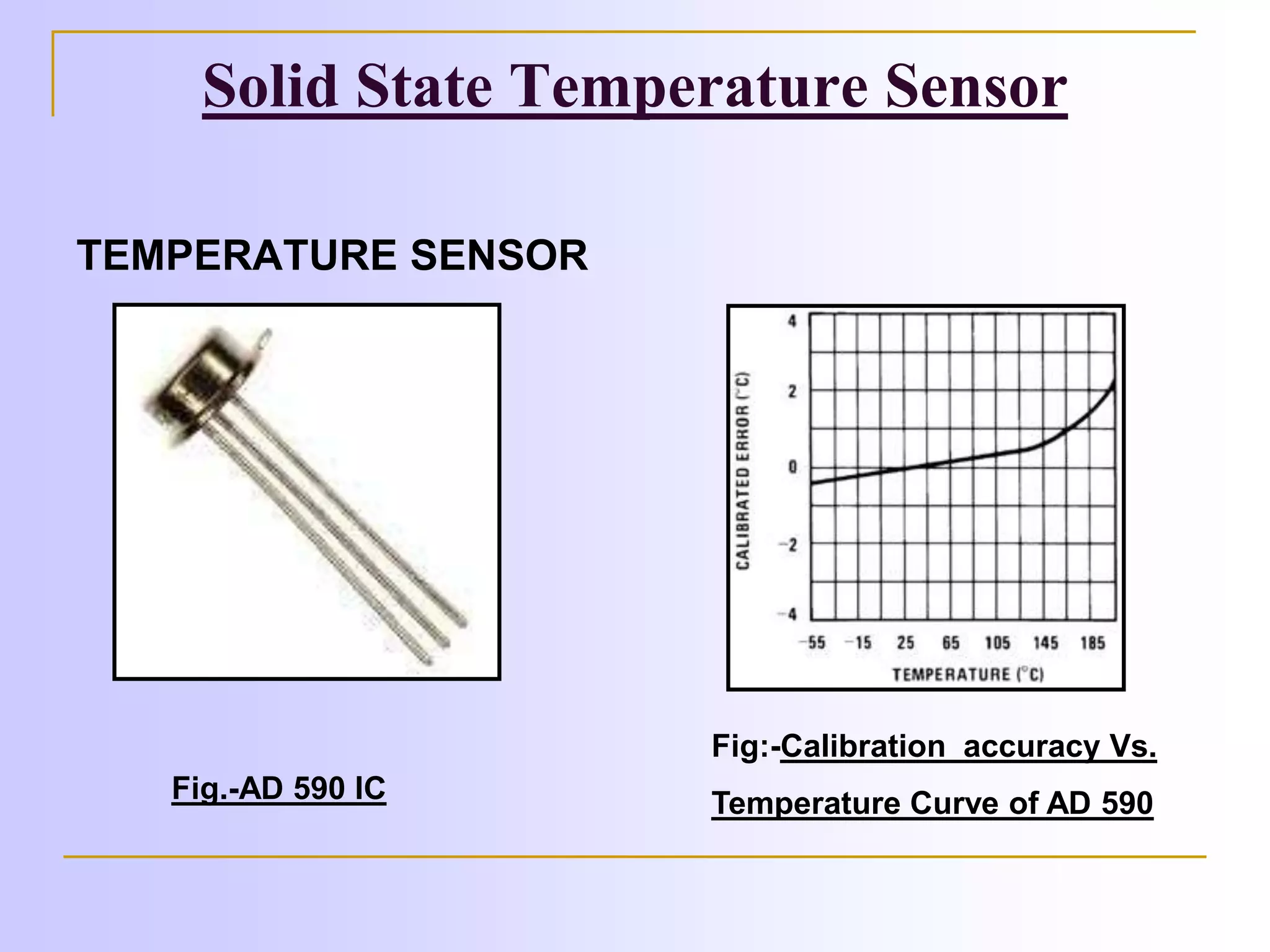
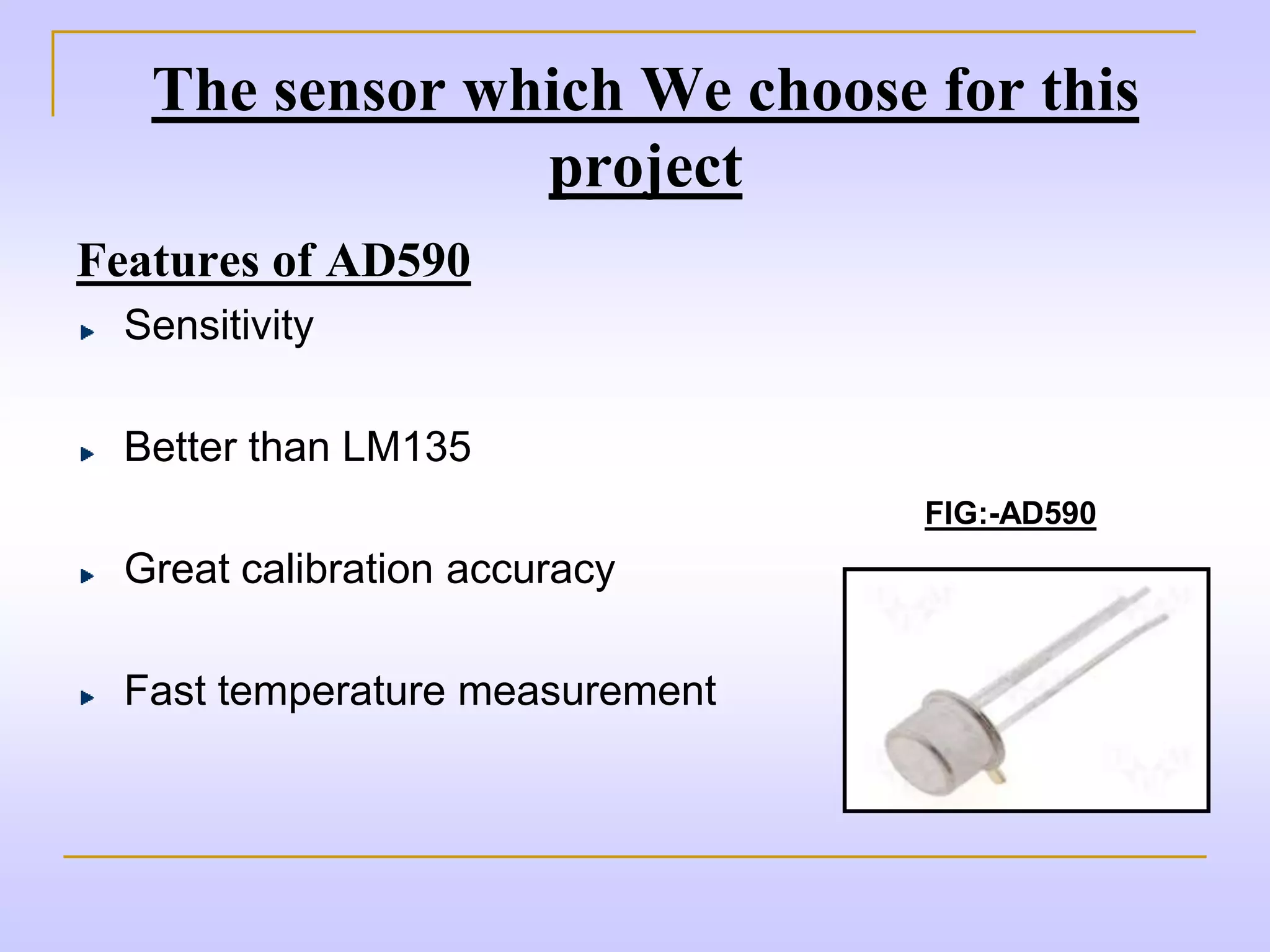
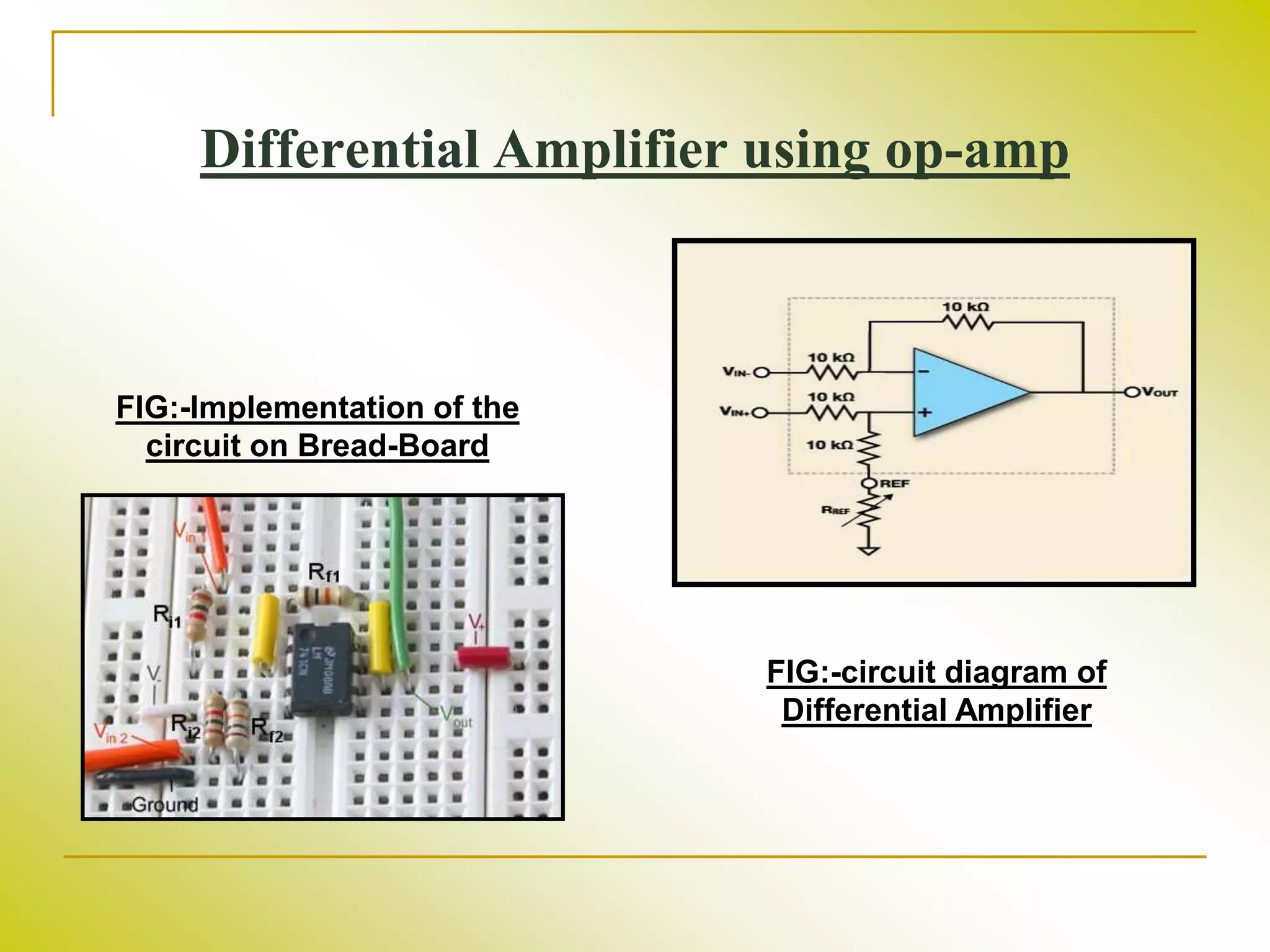
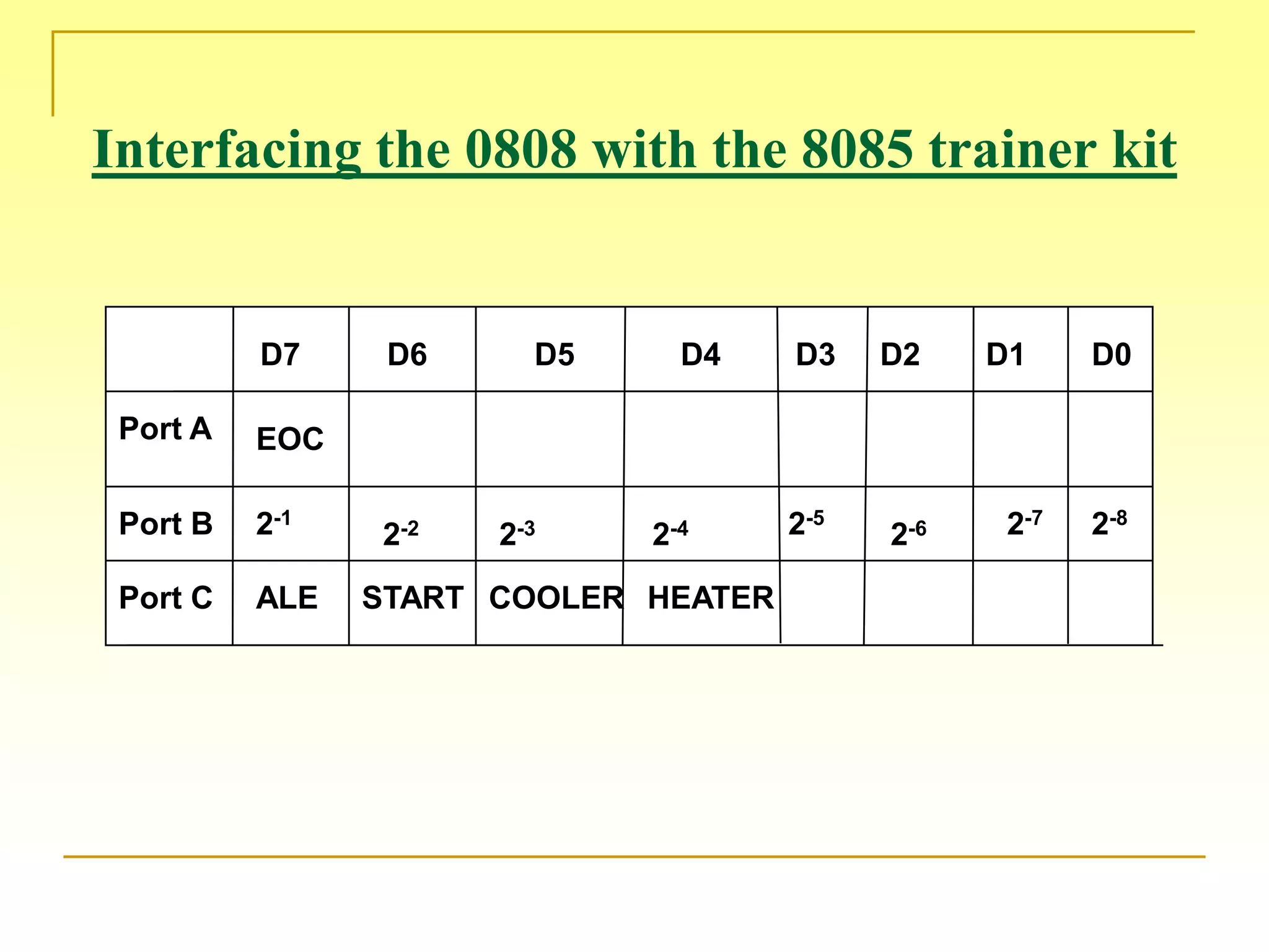
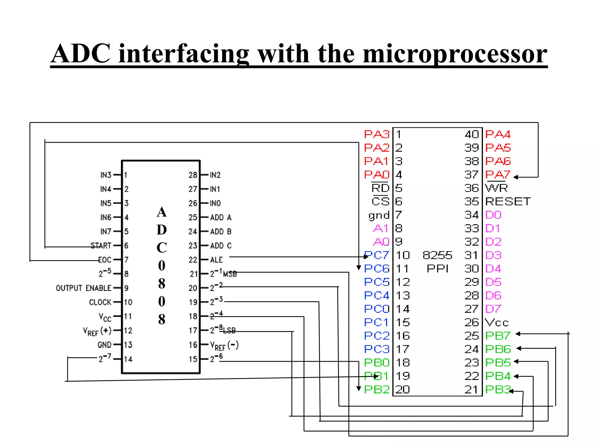
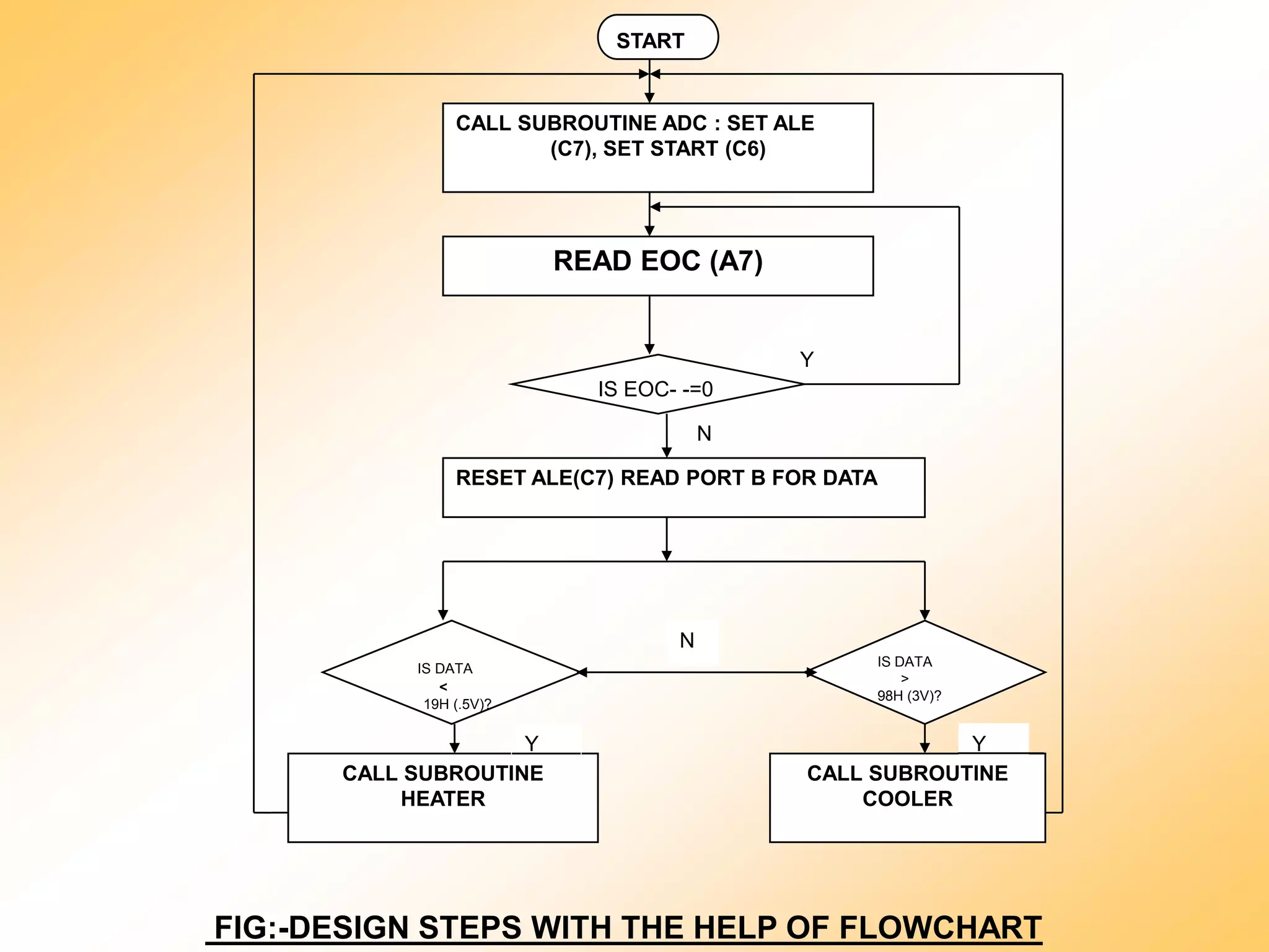
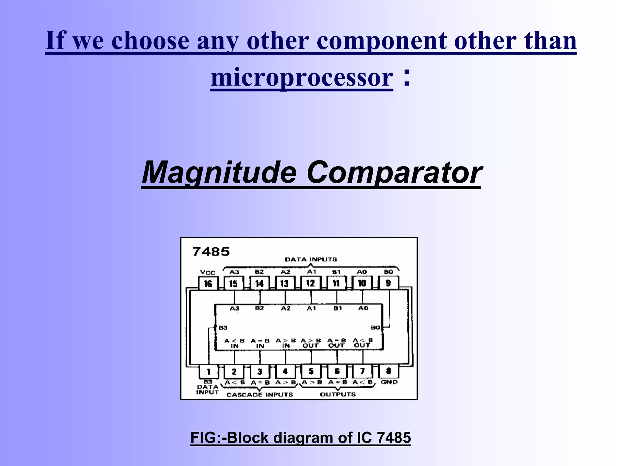
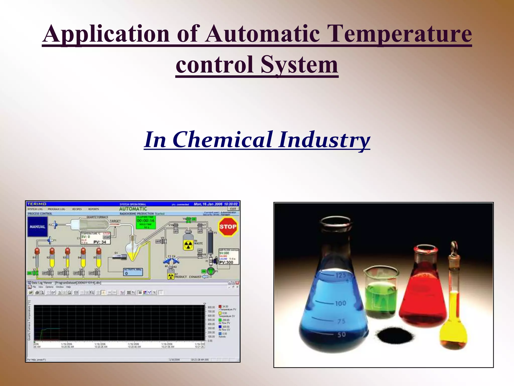
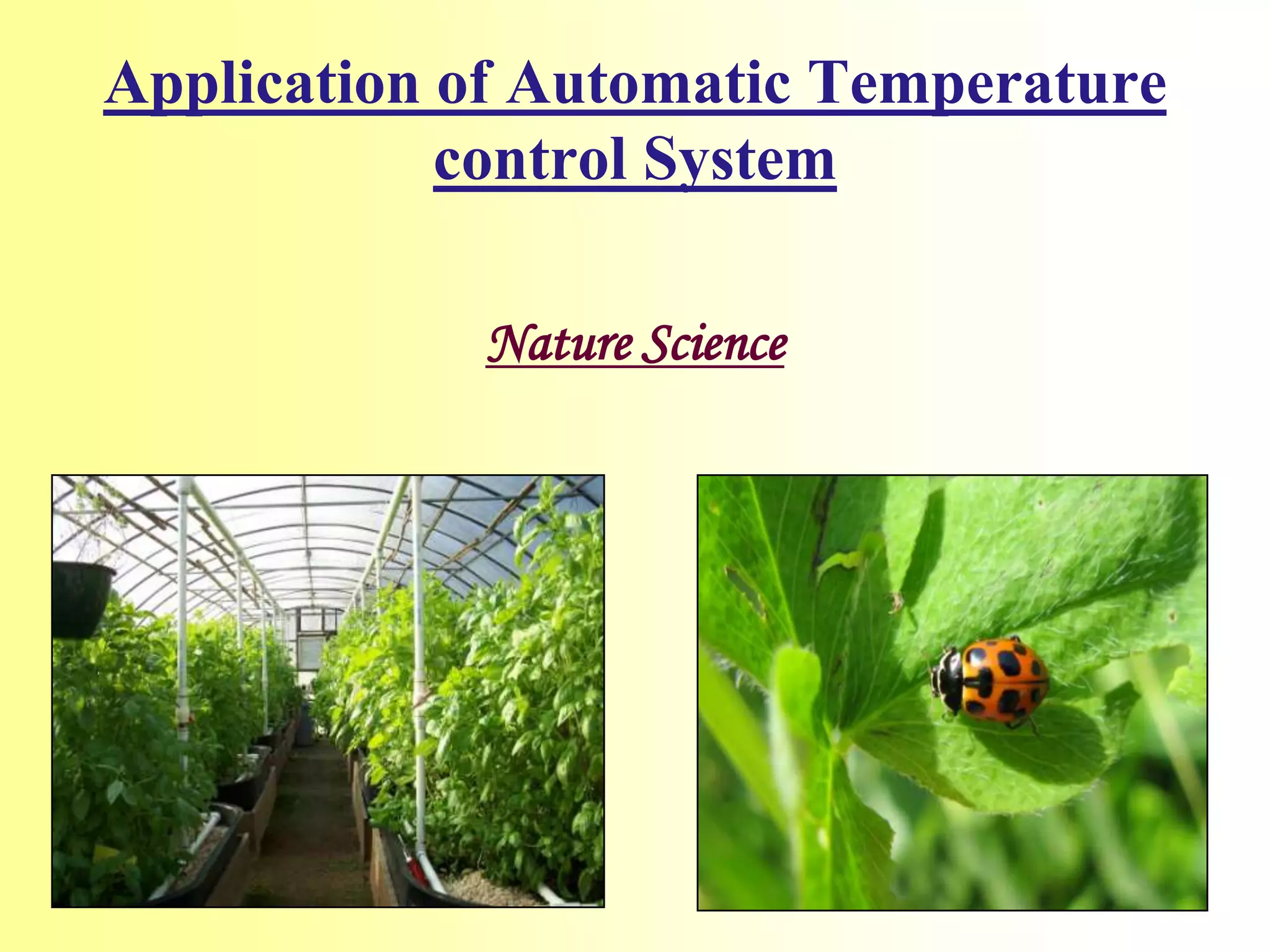
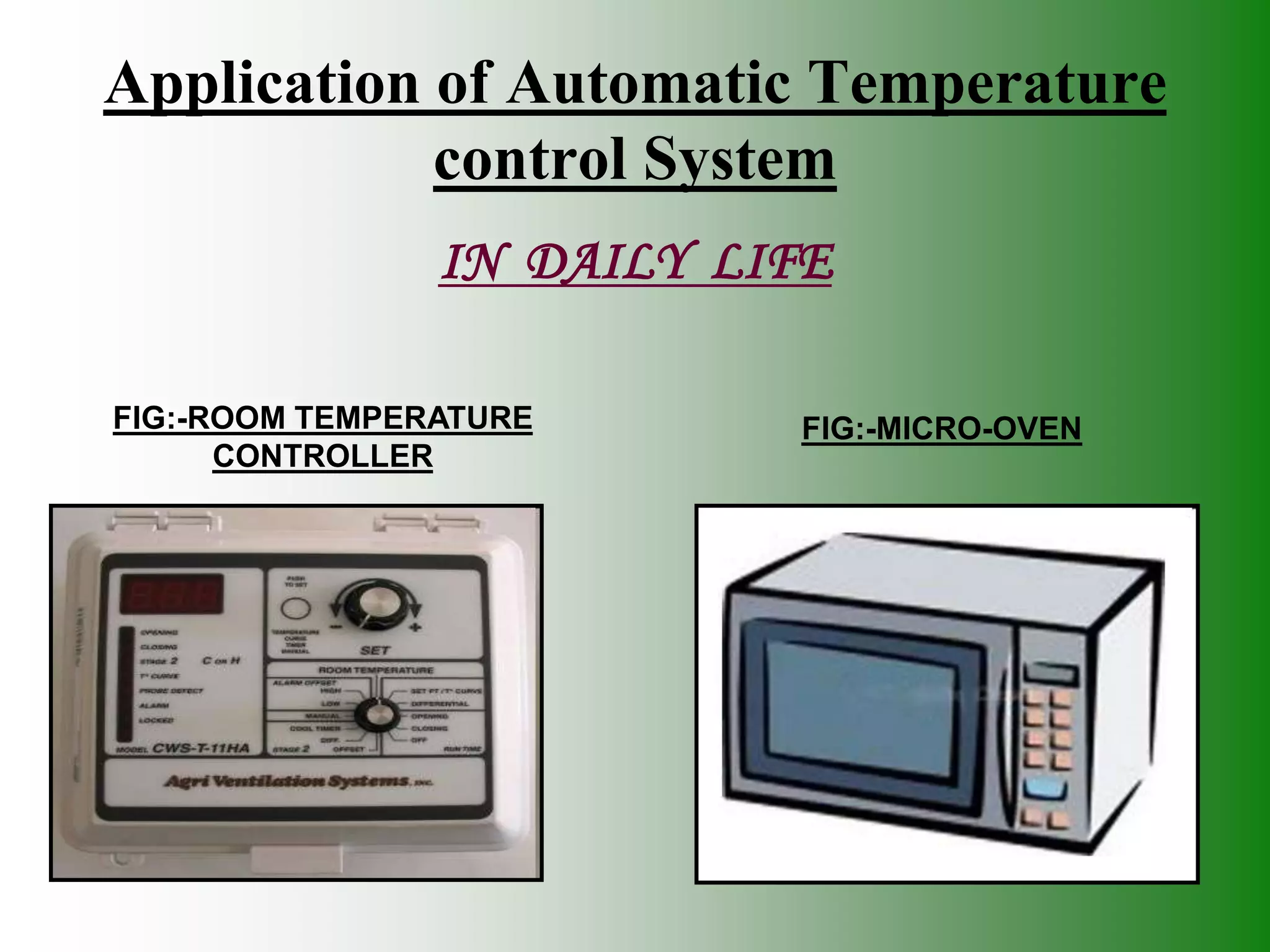


This document describes an automatic temperature control system using an 8085 microprocessor. The system uses an AD590 temperature sensor, differential amplifier, ADC0808 converter, and 8085 microprocessor to control a heater or cooler based on upper and lower temperature setpoints. The system aims to minimize manual intervention in industrial temperature control applications. Key components include the temperature input unit, processing unit, and control output unit. The system provides temperature control with minimal components at low cost.