SlideShare a Scribd company logo
1 of 11
FOR FULL SIZE SCALE
R.F.=1 OR ( 1:1 )
MEANS DRAWING
& OBJECT ARE OF
SAME SIZE.
Other RFs are described
as
1:10, 1:100,
1:1000, 1:1,00,000
SCALES
DIMENSIONS OF LARGE OBJECTS MUST BE REDUCED TO ACCOMMODATE
ON STANDARD SIZE DRAWING SHEET.THIS REDUCTION CREATES A SCALE
OF THAT REDUCTION RATIO, WHICH IS GENERALLY A FRACTION..
SUCH A SCALE IS CALLED REDUCING SCALE
AND
THAT RATIO IS CALLED REPRESENTATIVE FRACTION
SIMILARLY IN CASE OF TINY OBJECTS DIMENSIONS MUST BE INCREASED
FOR ABOVE PURPOSE. HENCE THIS SCALE IS CALLED ENLARGING SCALE.
USE FOLLOWING FORMULAS FOR THE CALCULATIONS IN THIS TOPIC.
B LENGTH OF SCALE (in cm) = R.F. X MAX. LENGTH TO BE MEASURED in cm.
REPRESENTATIVE FRACTION (R.F.)A =
LENGTH OF DRAWING in cm
ACTUAL LENGTH in cm
AREA OF DRAWING in cm²
ACTUAL AREA in cm²
=
V
=
VOLUME AS PER DRWG in cm³.
ACTUAL VOLUME in cm³V
3
1. PLAIN SCALES ( FOR DIMENSIONS UP TO SINGLE DECIMAL)
2. DIAGONAL SCALES ( FOR DIMENSIONS UP TO TWO DECIMALS)
3. VERNIER SCALES ( FOR DIMENSIONS UP TO TWO DECIMALS)
4. COMPARATIVE SCALES ( FOR COMPARING TWO DIFFERENT UNITS)
5. SCALE OF CHORDS ( FOR MEASURING/CONSTRUCTING ANGLES)
TYPES OF SCALES:
= 10 HECTOMETRES =105cm
= 10 DECAMETRES = 104cm
= 10 METRES = 103 cm
= 10 DECIMETRES = 102 cm
= 10 CENTIMETRES = 10 cm
= 10 MILIMETRES
1 KILOMETRE
1 HECTOMETRE
1 DECAMETRE
1 METRE
1 DECIMETRE
1 CENTIMETRE
BE FRIENDLY WITH THESE UNITS.
= 10000 m²1HECTARE
Area
1m2= 104 cm2
1m3= 106 cm3
Volume
Problem 01: A 3.2 cm long line represents a length of 4 metres. Extend this line to
measure lengths up to 25 metres and show on it units of metre and 5 metres. Find R.F &
L.O.S.
R.F=
Length on drawing in cm
Actual length of object in cm
=
3.2 cm
4 m
=
3.2 cm
4 x100cm
=
8
1000
=
1
125
L.O.S.= R.F.x Max. Length in cm =
1
125
X25X100 cm = 20 cm
We have seen that the plain scales give only two dimensions,
such as a unit and it’s subunit or it’s fraction.
1
2
3
4
5
6
7
8
9
10
X
Y
Z
The principle of construction of a diagonal scale is as follows.
Let the XY in figure be a subunit.
From Y draw a perpendicular YZ to a suitable height.
Join XZ. Divide YZ in to 10 equal parts.
Draw parallel lines to XY from all these divisions
and number them as shown.
From geometry we know that similar triangles have
their like sides proportional.
Consider two similar triangles XYZ and 7’ 7Z,
we have 7Z / YZ = 7’7 / XY (each part being one unit)
Means 7’ 7 = 7 / 10. x X Y = 0.7 XY
:.
Similarly
1’ – 1 = 0.1 XY
2’ – 2 = 0.2 XY
Thus, it is very clear that, the sides of small triangles,
which are parallel to divided lines, become progressively
shorter in length by 0.1 XY.
The diagonal scales give us three successive dimensions
that is a unit, a subunit and a subdivision of a subunit.
DIAGONAL
SCALE
Problem 7: Construct a diagonal scale of R.F. = 1/6250 to read up to 1 kilometre and to
read metres on it. Show a length of 653 metre on it.
R.F =
1
6250
Max. Length = 1 km,
L.O.S.= R.F.x Max. Length in cm
1
6250
= X 1X 105 cm = 16 cm
Hint: As the maximum length is 1 km, the line should be divided in to 10
equal parts, so as to represent a division of 100 m
0 100 200 300 400 500 600 700 800 900
METRE
50100
2
4
6
8
10
653
Problem 8: On a map, the distance between two points is 14 cm. The real distance
between them is 20 km. draw the diagonal scale of this map to read kilometre and
hectametres, and to measure up to 25 kilometre. Show a distance of 17.6 kilometre on
this scale.
R.F=
Length on drawing in cm
Actual length of object in cm
=
14 cm
20 km
=
14 cm
20X105 cm
=
7
106
L.O.S.= R.F.x Max. Length in cm =
7
106
X25X105 cm = 17.5 cm
Hint: As the maximum length is 25 km, the line should be either be
divided in to 25 equal parts to represent 1 km or first, in 5 equal parts
so as to represent a division of 5 km, then the first division in further 5
equal parts to represent 1 km.
0 5 10 15 20
KILOMETRE
12345
2
4
6
8
10
HECTOMETRE
17.6 km
R.F=
Area on drawing in cm²
Actual area of object in cm²
Problem 8: A rectangular plot of land measuring 1.28 hectors is represented on a map
by a similar rectangle of 8 sq.cm. Calculate RF of the scale. Draw a diagonal scale to
read single meter. Show a distance of 438 m on it. 1 hector = 104 m2
=
8 cm2
1.28X104x104 cm2
=
4
64X106
=
1
4000
L.O.S.= R.F.x Max. Length in cm =
1
4000
500 X 100 cm = 12.5 cmX
Here maximum length is not given. But we have to show a distance of
438 m on the scale. That will be possible only when maximum length is
taken as 500 m
0 100 200 300 400
METRE
2
4
6
8
10
438 m
50100
R.F. = 1 / 40,00,000
DIAGONAL SCALE SHOWING KILOMETERS.
0 100 200 300 400 500100 50
10
9
8
7
6
5
4
3
2
1
0
KM
KM
KM
569 km
459 km
336 km
222 km
PROBLEM NO. 4 : The distance between Delhi and Agra is 200 km.
In a railway map it is represented by a line 5 cm long. Find it’s R.F.
Draw a diagonal scale to show single km. And maximum 600 km.
Indicate on it following distances. 1) 222 km 2) 336 km 3) 459 km 4) 569 km
SOLUTION STEPS: RF = 5 cm / 200 km = 1 / 40, 00, 000
Length of scale = 1 / 40, 00, 000 X 600 X 105 = 15 cm
Draw a line 15 cm long. It will represent 600 km.Divide it in six equal parts.( each will represent 100 km.)
Divide first division in ten equal parts.Each will represent 10 km.Draw a line upward from left end and
mark 10 parts on it of any distance. Name those parts 0 to 10 as shown.Join 9th sub-division of horizontal scale
with 10th division of the vertical divisions. Then draw parallel lines to this line from remaining sub divisions and
complete diagonal scale.
DIAGONAL
SCALE
100
200
300
400
500
600
700
800 900
00
0 10 20 4030 7050 60 9080
SCALE OF CORDS
OA
CONSTRUCTION:
1. DRAW SECTOR OF A CIRCLE OF 900 WITH ‘OA’ RADIUS.
( ‘OA’ ANY CONVINIENT DISTANCE )
2. DIVIDE THIS ANGLE IN NINE EQUAL PARTS OF 10 0 EACH.
3. NAME AS SHOWN FROM END ‘A’ UPWARDS.
4. FROM ‘A’ AS CENTER, WITH CORDS OF EACH ANGLE AS RADIUS
DRAW ARCS DOWNWARDS UP TO ‘AO’ LINE OR IT’S EXTENSION
AND FORM A SCALE WITH PROPER LABELING AS SHOWN.
AS CORD LENGTHS ARE USED TO MEASURE & CONSTRUCT
DIFERENT ANGLES IT IS CALLED SCALE OF CORDS.
100
200
300
400
500
600
700 800 900
00
0 10 20 4030 7050 60 9080
OA
OA
B
O1 A1
B1
x
z
y
PROBLEM 12: Construct any triangle and measure it’s angles by using scale of cords.
CONSTRUCTION:
First prepare Scale of Cords for the problem.
Then construct a triangle of given sides. ( You are supposed to measure angles x, y and z)
To measure angle at x:
Take O-A distance in compass from cords scale and mark it on lower side of triangle
as shown from corner x. Name O & A as shown. Then O as center, O-A radius
draw an arc upto upper adjacent side.Name the point B.
Take A-B cord in compass and place on scale of cords from Zero.
It will give value of angle at x
To measure angle at y:
Repeat same process from O1. Draw arc with radius O1A1.
Place Cord A1B1 on scale and get angle at y.
To measure angle at z:
Subtract the SUM of these two angles from 1800 to get angle at z.
SCALE OF CORDS
300550
Angle at z = 180 – ( 55 + 30 ) = 950
100
200
300
400
500
600
700 800 900
00
0 10 20 4030 7050 60 9080
OA
PROBLEM 12: Construct 250 and 1150 angles with a horizontal line , by using scale of cords.
CONSTRUCTION:
First prepare Scale of Cords for the problem.
Then Draw a horizontal line. Mark point O on it.
To construct 250 angle at O.
Take O-A distance in compass from cords scale and mark it on on the line drawn, from O
Name O & A as shown. Then O as center, O-A radius draw an arc upward..
Take cord length of 250 angle from scale of cords in compass and
from A cut the arc at point B.Join B with O. The angle AOB is thus 250
To construct 1150 angle at O.
This scale can measure or construct angles upto 900 only directly.
Hence Subtract 1150 from 1800.We get 750 angle ,
which can be constructed with this scale.
Extend previous arc of OA radius and taking cord length of 750 in compass cut this arc
at B1 with A as center. Join B1 with O. Now angle AOB1 is 750 and angle COB1 is 1150.
SCALE OF CORDS
B1
750
1050
B
250
A O
O
C
A
To construct 250 angle at O. To construct 1150 angle at O.

More Related Content

What's hot

Engineering drawing (geometric construction) lesson 4
Engineering drawing (geometric construction) lesson 4Engineering drawing (geometric construction) lesson 4
Engineering drawing (geometric construction) lesson 4hermiraguilar
 
First and third angle projection
First and third angle projectionFirst and third angle projection
First and third angle projectionSafiullah Khan
 
Geometricalconstruction
GeometricalconstructionGeometricalconstruction
GeometricalconstructionSaidon Aziz
 
Engineering drawing
Engineering  drawing Engineering  drawing
Engineering drawing Selva Prakash
 
1- introduction Graphic and geometric graphics Engineering.
1- introduction Graphic and geometric graphics Engineering.1- introduction Graphic and geometric graphics Engineering.
1- introduction Graphic and geometric graphics Engineering.Abo Talak Al-wayli
 
ENGINEERING GRAPHICS
ENGINEERING GRAPHICSENGINEERING GRAPHICS
ENGINEERING GRAPHICSSAGAR SINGH
 
Unit 1 orthographic projection engineering graphics
Unit 1 orthographic projection engineering graphicsUnit 1 orthographic projection engineering graphics
Unit 1 orthographic projection engineering graphicsganesasmoorthy raju
 
Scales - ENGINEERING DRAWING/GRAPHICS
Scales - ENGINEERING DRAWING/GRAPHICSScales - ENGINEERING DRAWING/GRAPHICS
Scales - ENGINEERING DRAWING/GRAPHICSAbhishek Kandare
 
Drawing presentation 2015 2016
Drawing presentation 2015 2016Drawing presentation 2015 2016
Drawing presentation 2015 2016muralbe1
 
Orthographic projection
Orthographic projectionOrthographic projection
Orthographic projectionKashyap Shah
 
Plain scale and Diagonal Scale Engineering Graphics
Plain scale and Diagonal Scale Engineering GraphicsPlain scale and Diagonal Scale Engineering Graphics
Plain scale and Diagonal Scale Engineering GraphicsR A Shah
 

What's hot (20)

Engineering drawing
Engineering drawingEngineering drawing
Engineering drawing
 
Unit ii projection of points
Unit  ii projection of pointsUnit  ii projection of points
Unit ii projection of points
 
Isometric projection
Isometric projectionIsometric projection
Isometric projection
 
Engineering drawing (geometric construction) lesson 4
Engineering drawing (geometric construction) lesson 4Engineering drawing (geometric construction) lesson 4
Engineering drawing (geometric construction) lesson 4
 
First and third angle projection
First and third angle projectionFirst and third angle projection
First and third angle projection
 
Geometricalconstruction
GeometricalconstructionGeometricalconstruction
Geometricalconstruction
 
Engineering drawing
Engineering  drawing Engineering  drawing
Engineering drawing
 
1- introduction Graphic and geometric graphics Engineering.
1- introduction Graphic and geometric graphics Engineering.1- introduction Graphic and geometric graphics Engineering.
1- introduction Graphic and geometric graphics Engineering.
 
Scales
ScalesScales
Scales
 
ENGINEERING GRAPHICS
ENGINEERING GRAPHICSENGINEERING GRAPHICS
ENGINEERING GRAPHICS
 
Unit 1 orthographic projection engineering graphics
Unit 1 orthographic projection engineering graphicsUnit 1 orthographic projection engineering graphics
Unit 1 orthographic projection engineering graphics
 
Scales - ENGINEERING DRAWING/GRAPHICS
Scales - ENGINEERING DRAWING/GRAPHICSScales - ENGINEERING DRAWING/GRAPHICS
Scales - ENGINEERING DRAWING/GRAPHICS
 
Drawing presentation 2015 2016
Drawing presentation 2015 2016Drawing presentation 2015 2016
Drawing presentation 2015 2016
 
Orthographic projection
Orthographic projectionOrthographic projection
Orthographic projection
 
Isometric
IsometricIsometric
Isometric
 
Orthographic projection
Orthographic projectionOrthographic projection
Orthographic projection
 
Technical Drawing
Technical DrawingTechnical Drawing
Technical Drawing
 
Plain scale and Diagonal Scale Engineering Graphics
Plain scale and Diagonal Scale Engineering GraphicsPlain scale and Diagonal Scale Engineering Graphics
Plain scale and Diagonal Scale Engineering Graphics
 
Isometric projections
Isometric projectionsIsometric projections
Isometric projections
 
Curve1
Curve1Curve1
Curve1
 

Viewers also liked

Section and development
Section and developmentSection and development
Section and developmentgtuautonomous
 
Scales-engineering drawing b.tech
Scales-engineering drawing b.techScales-engineering drawing b.tech
Scales-engineering drawing b.techMohd Mujahid Nasir
 
Class 2 presentation posted
Class 2 presentation postedClass 2 presentation posted
Class 2 presentation postedlaura_gerold
 
Ms project general introduction
Ms project general introductionMs project general introduction
Ms project general introductionKushal Patel
 
Uts congestion components
Uts congestion componentsUts congestion components
Uts congestion componentsKushal Patel
 
Key factors related to traffic crashes by Malyar Talash
Key factors related to traffic crashes by Malyar TalashKey factors related to traffic crashes by Malyar Talash
Key factors related to traffic crashes by Malyar TalashMalyar Talash
 
Survey responses
Survey responsesSurvey responses
Survey responsesscarlet2882
 
sMs project tutorial_iit
sMs project tutorial_iitsMs project tutorial_iit
sMs project tutorial_iitKushal Patel
 
Civil 3 d overview general
Civil 3 d overview generalCivil 3 d overview general
Civil 3 d overview generalKushal Patel
 
Moscow, ID case study traffic operation
Moscow, ID case study traffic operationMoscow, ID case study traffic operation
Moscow, ID case study traffic operationKushal Patel
 
Acts & Plot points
Acts & Plot pointsActs & Plot points
Acts & Plot pointsiain bruce
 
Presentation hcm 2010 case study
Presentation hcm 2010 case studyPresentation hcm 2010 case study
Presentation hcm 2010 case studyKushal Patel
 
Enviromental impact assesment for highway projects
Enviromental impact assesment for highway projectsEnviromental impact assesment for highway projects
Enviromental impact assesment for highway projectsKushal Patel
 
Tunnel example for road project by Malyar Talash
Tunnel example for road project by Malyar TalashTunnel example for road project by Malyar Talash
Tunnel example for road project by Malyar TalashMalyar Talash
 

Viewers also liked (20)

Section and development
Section and developmentSection and development
Section and development
 
Scales-engineering drawing b.tech
Scales-engineering drawing b.techScales-engineering drawing b.tech
Scales-engineering drawing b.tech
 
Scales
ScalesScales
Scales
 
Scales
ScalesScales
Scales
 
Scales
ScalesScales
Scales
 
Scale engineering
Scale engineeringScale engineering
Scale engineering
 
Class 2 presentation posted
Class 2 presentation postedClass 2 presentation posted
Class 2 presentation posted
 
Ms project general introduction
Ms project general introductionMs project general introduction
Ms project general introduction
 
Uts congestion components
Uts congestion componentsUts congestion components
Uts congestion components
 
Key factors related to traffic crashes by Malyar Talash
Key factors related to traffic crashes by Malyar TalashKey factors related to traffic crashes by Malyar Talash
Key factors related to traffic crashes by Malyar Talash
 
Survey responses
Survey responsesSurvey responses
Survey responses
 
Seminar
SeminarSeminar
Seminar
 
sMs project tutorial_iit
sMs project tutorial_iitsMs project tutorial_iit
sMs project tutorial_iit
 
Coordinate Systems
Coordinate SystemsCoordinate Systems
Coordinate Systems
 
Civil 3 d overview general
Civil 3 d overview generalCivil 3 d overview general
Civil 3 d overview general
 
Moscow, ID case study traffic operation
Moscow, ID case study traffic operationMoscow, ID case study traffic operation
Moscow, ID case study traffic operation
 
Acts & Plot points
Acts & Plot pointsActs & Plot points
Acts & Plot points
 
Presentation hcm 2010 case study
Presentation hcm 2010 case studyPresentation hcm 2010 case study
Presentation hcm 2010 case study
 
Enviromental impact assesment for highway projects
Enviromental impact assesment for highway projectsEnviromental impact assesment for highway projects
Enviromental impact assesment for highway projects
 
Tunnel example for road project by Malyar Talash
Tunnel example for road project by Malyar TalashTunnel example for road project by Malyar Talash
Tunnel example for road project by Malyar Talash
 

Similar to Scales in Engineering

Similar to Scales in Engineering (20)

B.tech i eg u1 scale
B.tech  i eg u1 scaleB.tech  i eg u1 scale
B.tech i eg u1 scale
 
Scales
ScalesScales
Scales
 
Scale and its types
Scale and its types Scale and its types
Scale and its types
 
SCALE
SCALESCALE
SCALE
 
EDP.pptx
EDP.pptxEDP.pptx
EDP.pptx
 
construction of ellipse and scales
construction of ellipse and scalesconstruction of ellipse and scales
construction of ellipse and scales
 
ED PPT_0.pdf
ED PPT_0.pdfED PPT_0.pdf
ED PPT_0.pdf
 
4.scale engineering108.com
4.scale engineering108.com4.scale engineering108.com
4.scale engineering108.com
 
Slideshare Engineering Graphics
Slideshare Engineering GraphicsSlideshare Engineering Graphics
Slideshare Engineering Graphics
 
Scales
ScalesScales
Scales
 
Scales
ScalesScales
Scales
 
Varun Unit1
Varun Unit1Varun Unit1
Varun Unit1
 
construction of SCALES
construction  of  SCALES construction  of  SCALES
construction of SCALES
 
SCALES : ENGINEERING, Plain and diagonal
SCALES : ENGINEERING,  Plain  and diagonal SCALES : ENGINEERING,  Plain  and diagonal
SCALES : ENGINEERING, Plain and diagonal
 
Scales.pptx
Scales.pptxScales.pptx
Scales.pptx
 
Scales.pptx
Scales.pptxScales.pptx
Scales.pptx
 
Plain scale Engineering Graphics
Plain scale Engineering GraphicsPlain scale Engineering Graphics
Plain scale Engineering Graphics
 
Scales +problems
Scales +problemsScales +problems
Scales +problems
 
Isometric - ENGINEERING DRAWING/GRAPHICS
Isometric - ENGINEERING DRAWING/GRAPHICSIsometric - ENGINEERING DRAWING/GRAPHICS
Isometric - ENGINEERING DRAWING/GRAPHICS
 
Eg1 n
Eg1 nEg1 n
Eg1 n
 

More from Kushal Patel

Ms project working example
Ms project working exampleMs project working example
Ms project working exampleKushal Patel
 
Design guidance for freeway mainline ramp terminals
Design guidance for freeway mainline ramp terminalsDesign guidance for freeway mainline ramp terminals
Design guidance for freeway mainline ramp terminalsKushal Patel
 
Autodesk civil3 d_tutorail
Autodesk civil3 d_tutorailAutodesk civil3 d_tutorail
Autodesk civil3 d_tutorailKushal Patel
 
Types of bridge(theory.explanation)
Types of bridge(theory.explanation)Types of bridge(theory.explanation)
Types of bridge(theory.explanation)Kushal Patel
 
Types of bridge(concept)
Types of bridge(concept)Types of bridge(concept)
Types of bridge(concept)Kushal Patel
 
Eia methods for transportation project
Eia methods for transportation projectEia methods for transportation project
Eia methods for transportation projectKushal Patel
 
Plane table survey
Plane table surveyPlane table survey
Plane table surveyKushal Patel
 
Airport lighting airport engineering
Airport lighting  airport engineeringAirport lighting  airport engineering
Airport lighting airport engineeringKushal Patel
 

More from Kushal Patel (10)

Ms project working example
Ms project working exampleMs project working example
Ms project working example
 
Design guidance for freeway mainline ramp terminals
Design guidance for freeway mainline ramp terminalsDesign guidance for freeway mainline ramp terminals
Design guidance for freeway mainline ramp terminals
 
Autodesk civil3 d_tutorail
Autodesk civil3 d_tutorailAutodesk civil3 d_tutorail
Autodesk civil3 d_tutorail
 
Types of bridge(theory.explanation)
Types of bridge(theory.explanation)Types of bridge(theory.explanation)
Types of bridge(theory.explanation)
 
Types of bridge(concept)
Types of bridge(concept)Types of bridge(concept)
Types of bridge(concept)
 
Eia methods for transportation project
Eia methods for transportation projectEia methods for transportation project
Eia methods for transportation project
 
Plane table survey
Plane table surveyPlane table survey
Plane table survey
 
Land use planning
Land use planningLand use planning
Land use planning
 
Airport lighting airport engineering
Airport lighting  airport engineeringAirport lighting  airport engineering
Airport lighting airport engineering
 
Road geometrics
Road geometricsRoad geometrics
Road geometrics
 

Recently uploaded

Work-Permit-Receiver-in-Saudi-Aramco.pptx
Work-Permit-Receiver-in-Saudi-Aramco.pptxWork-Permit-Receiver-in-Saudi-Aramco.pptx
Work-Permit-Receiver-in-Saudi-Aramco.pptxJuliansyahHarahap1
 
Generative AI or GenAI technology based PPT
Generative AI or GenAI technology based PPTGenerative AI or GenAI technology based PPT
Generative AI or GenAI technology based PPTbhaskargani46
 
Double Revolving field theory-how the rotor develops torque
Double Revolving field theory-how the rotor develops torqueDouble Revolving field theory-how the rotor develops torque
Double Revolving field theory-how the rotor develops torqueBhangaleSonal
 
University management System project report..pdf
University management System project report..pdfUniversity management System project report..pdf
University management System project report..pdfKamal Acharya
 
Unleashing the Power of the SORA AI lastest leap
Unleashing the Power of the SORA AI lastest leapUnleashing the Power of the SORA AI lastest leap
Unleashing the Power of the SORA AI lastest leapRishantSharmaFr
 
DC MACHINE-Motoring and generation, Armature circuit equation
DC MACHINE-Motoring and generation, Armature circuit equationDC MACHINE-Motoring and generation, Armature circuit equation
DC MACHINE-Motoring and generation, Armature circuit equationBhangaleSonal
 
Design For Accessibility: Getting it right from the start
Design For Accessibility: Getting it right from the startDesign For Accessibility: Getting it right from the start
Design For Accessibility: Getting it right from the startQuintin Balsdon
 
FULL ENJOY Call Girls In Mahipalpur Delhi Contact Us 8377877756
FULL ENJOY Call Girls In Mahipalpur Delhi Contact Us 8377877756FULL ENJOY Call Girls In Mahipalpur Delhi Contact Us 8377877756
FULL ENJOY Call Girls In Mahipalpur Delhi Contact Us 8377877756dollysharma2066
 
Block diagram reduction techniques in control systems.ppt
Block diagram reduction techniques in control systems.pptBlock diagram reduction techniques in control systems.ppt
Block diagram reduction techniques in control systems.pptNANDHAKUMARA10
 
Hazard Identification (HAZID) vs. Hazard and Operability (HAZOP): A Comparati...
Hazard Identification (HAZID) vs. Hazard and Operability (HAZOP): A Comparati...Hazard Identification (HAZID) vs. Hazard and Operability (HAZOP): A Comparati...
Hazard Identification (HAZID) vs. Hazard and Operability (HAZOP): A Comparati...soginsider
 
Minimum and Maximum Modes of microprocessor 8086
Minimum and Maximum Modes of microprocessor 8086Minimum and Maximum Modes of microprocessor 8086
Minimum and Maximum Modes of microprocessor 8086anil_gaur
 
VIP Call Girls Palanpur 7001035870 Whatsapp Number, 24/07 Booking
VIP Call Girls Palanpur 7001035870 Whatsapp Number, 24/07 BookingVIP Call Girls Palanpur 7001035870 Whatsapp Number, 24/07 Booking
VIP Call Girls Palanpur 7001035870 Whatsapp Number, 24/07 Bookingdharasingh5698
 
notes on Evolution Of Analytic Scalability.ppt
notes on Evolution Of Analytic Scalability.pptnotes on Evolution Of Analytic Scalability.ppt
notes on Evolution Of Analytic Scalability.pptMsecMca
 
22-prompt engineering noted slide shown.pdf
22-prompt engineering noted slide shown.pdf22-prompt engineering noted slide shown.pdf
22-prompt engineering noted slide shown.pdf203318pmpc
 
Top Rated Call Girls In chittoor 📱 {7001035870} VIP Escorts chittoor
Top Rated Call Girls In chittoor 📱 {7001035870} VIP Escorts chittoorTop Rated Call Girls In chittoor 📱 {7001035870} VIP Escorts chittoor
Top Rated Call Girls In chittoor 📱 {7001035870} VIP Escorts chittoordharasingh5698
 
Thermal Engineering -unit - III & IV.ppt
Thermal Engineering -unit - III & IV.pptThermal Engineering -unit - III & IV.ppt
Thermal Engineering -unit - III & IV.pptDineshKumar4165
 

Recently uploaded (20)

Work-Permit-Receiver-in-Saudi-Aramco.pptx
Work-Permit-Receiver-in-Saudi-Aramco.pptxWork-Permit-Receiver-in-Saudi-Aramco.pptx
Work-Permit-Receiver-in-Saudi-Aramco.pptx
 
Generative AI or GenAI technology based PPT
Generative AI or GenAI technology based PPTGenerative AI or GenAI technology based PPT
Generative AI or GenAI technology based PPT
 
Double Revolving field theory-how the rotor develops torque
Double Revolving field theory-how the rotor develops torqueDouble Revolving field theory-how the rotor develops torque
Double Revolving field theory-how the rotor develops torque
 
University management System project report..pdf
University management System project report..pdfUniversity management System project report..pdf
University management System project report..pdf
 
Call Now ≽ 9953056974 ≼🔝 Call Girls In New Ashok Nagar ≼🔝 Delhi door step de...
Call Now ≽ 9953056974 ≼🔝 Call Girls In New Ashok Nagar  ≼🔝 Delhi door step de...Call Now ≽ 9953056974 ≼🔝 Call Girls In New Ashok Nagar  ≼🔝 Delhi door step de...
Call Now ≽ 9953056974 ≼🔝 Call Girls In New Ashok Nagar ≼🔝 Delhi door step de...
 
(INDIRA) Call Girl Bhosari Call Now 8617697112 Bhosari Escorts 24x7
(INDIRA) Call Girl Bhosari Call Now 8617697112 Bhosari Escorts 24x7(INDIRA) Call Girl Bhosari Call Now 8617697112 Bhosari Escorts 24x7
(INDIRA) Call Girl Bhosari Call Now 8617697112 Bhosari Escorts 24x7
 
Unleashing the Power of the SORA AI lastest leap
Unleashing the Power of the SORA AI lastest leapUnleashing the Power of the SORA AI lastest leap
Unleashing the Power of the SORA AI lastest leap
 
DC MACHINE-Motoring and generation, Armature circuit equation
DC MACHINE-Motoring and generation, Armature circuit equationDC MACHINE-Motoring and generation, Armature circuit equation
DC MACHINE-Motoring and generation, Armature circuit equation
 
Design For Accessibility: Getting it right from the start
Design For Accessibility: Getting it right from the startDesign For Accessibility: Getting it right from the start
Design For Accessibility: Getting it right from the start
 
FULL ENJOY Call Girls In Mahipalpur Delhi Contact Us 8377877756
FULL ENJOY Call Girls In Mahipalpur Delhi Contact Us 8377877756FULL ENJOY Call Girls In Mahipalpur Delhi Contact Us 8377877756
FULL ENJOY Call Girls In Mahipalpur Delhi Contact Us 8377877756
 
Block diagram reduction techniques in control systems.ppt
Block diagram reduction techniques in control systems.pptBlock diagram reduction techniques in control systems.ppt
Block diagram reduction techniques in control systems.ppt
 
Hazard Identification (HAZID) vs. Hazard and Operability (HAZOP): A Comparati...
Hazard Identification (HAZID) vs. Hazard and Operability (HAZOP): A Comparati...Hazard Identification (HAZID) vs. Hazard and Operability (HAZOP): A Comparati...
Hazard Identification (HAZID) vs. Hazard and Operability (HAZOP): A Comparati...
 
Integrated Test Rig For HTFE-25 - Neometrix
Integrated Test Rig For HTFE-25 - NeometrixIntegrated Test Rig For HTFE-25 - Neometrix
Integrated Test Rig For HTFE-25 - Neometrix
 
FEA Based Level 3 Assessment of Deformed Tanks with Fluid Induced Loads
FEA Based Level 3 Assessment of Deformed Tanks with Fluid Induced LoadsFEA Based Level 3 Assessment of Deformed Tanks with Fluid Induced Loads
FEA Based Level 3 Assessment of Deformed Tanks with Fluid Induced Loads
 
Minimum and Maximum Modes of microprocessor 8086
Minimum and Maximum Modes of microprocessor 8086Minimum and Maximum Modes of microprocessor 8086
Minimum and Maximum Modes of microprocessor 8086
 
VIP Call Girls Palanpur 7001035870 Whatsapp Number, 24/07 Booking
VIP Call Girls Palanpur 7001035870 Whatsapp Number, 24/07 BookingVIP Call Girls Palanpur 7001035870 Whatsapp Number, 24/07 Booking
VIP Call Girls Palanpur 7001035870 Whatsapp Number, 24/07 Booking
 
notes on Evolution Of Analytic Scalability.ppt
notes on Evolution Of Analytic Scalability.pptnotes on Evolution Of Analytic Scalability.ppt
notes on Evolution Of Analytic Scalability.ppt
 
22-prompt engineering noted slide shown.pdf
22-prompt engineering noted slide shown.pdf22-prompt engineering noted slide shown.pdf
22-prompt engineering noted slide shown.pdf
 
Top Rated Call Girls In chittoor 📱 {7001035870} VIP Escorts chittoor
Top Rated Call Girls In chittoor 📱 {7001035870} VIP Escorts chittoorTop Rated Call Girls In chittoor 📱 {7001035870} VIP Escorts chittoor
Top Rated Call Girls In chittoor 📱 {7001035870} VIP Escorts chittoor
 
Thermal Engineering -unit - III & IV.ppt
Thermal Engineering -unit - III & IV.pptThermal Engineering -unit - III & IV.ppt
Thermal Engineering -unit - III & IV.ppt
 

Scales in Engineering

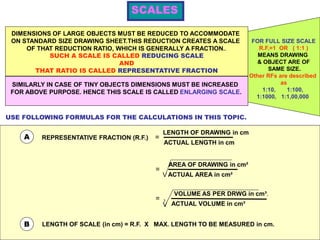
  • 1. FOR FULL SIZE SCALE R.F.=1 OR ( 1:1 ) MEANS DRAWING & OBJECT ARE OF SAME SIZE. Other RFs are described as 1:10, 1:100, 1:1000, 1:1,00,000 SCALES DIMENSIONS OF LARGE OBJECTS MUST BE REDUCED TO ACCOMMODATE ON STANDARD SIZE DRAWING SHEET.THIS REDUCTION CREATES A SCALE OF THAT REDUCTION RATIO, WHICH IS GENERALLY A FRACTION.. SUCH A SCALE IS CALLED REDUCING SCALE AND THAT RATIO IS CALLED REPRESENTATIVE FRACTION SIMILARLY IN CASE OF TINY OBJECTS DIMENSIONS MUST BE INCREASED FOR ABOVE PURPOSE. HENCE THIS SCALE IS CALLED ENLARGING SCALE. USE FOLLOWING FORMULAS FOR THE CALCULATIONS IN THIS TOPIC. B LENGTH OF SCALE (in cm) = R.F. X MAX. LENGTH TO BE MEASURED in cm. REPRESENTATIVE FRACTION (R.F.)A = LENGTH OF DRAWING in cm ACTUAL LENGTH in cm AREA OF DRAWING in cm² ACTUAL AREA in cm² = V = VOLUME AS PER DRWG in cm³. ACTUAL VOLUME in cm³V 3
  • 2. 1. PLAIN SCALES ( FOR DIMENSIONS UP TO SINGLE DECIMAL) 2. DIAGONAL SCALES ( FOR DIMENSIONS UP TO TWO DECIMALS) 3. VERNIER SCALES ( FOR DIMENSIONS UP TO TWO DECIMALS) 4. COMPARATIVE SCALES ( FOR COMPARING TWO DIFFERENT UNITS) 5. SCALE OF CHORDS ( FOR MEASURING/CONSTRUCTING ANGLES) TYPES OF SCALES: = 10 HECTOMETRES =105cm = 10 DECAMETRES = 104cm = 10 METRES = 103 cm = 10 DECIMETRES = 102 cm = 10 CENTIMETRES = 10 cm = 10 MILIMETRES 1 KILOMETRE 1 HECTOMETRE 1 DECAMETRE 1 METRE 1 DECIMETRE 1 CENTIMETRE BE FRIENDLY WITH THESE UNITS. = 10000 m²1HECTARE Area 1m2= 104 cm2 1m3= 106 cm3 Volume
  • 3. Problem 01: A 3.2 cm long line represents a length of 4 metres. Extend this line to measure lengths up to 25 metres and show on it units of metre and 5 metres. Find R.F & L.O.S. R.F= Length on drawing in cm Actual length of object in cm = 3.2 cm 4 m = 3.2 cm 4 x100cm = 8 1000 = 1 125 L.O.S.= R.F.x Max. Length in cm = 1 125 X25X100 cm = 20 cm
  • 4. We have seen that the plain scales give only two dimensions, such as a unit and it’s subunit or it’s fraction. 1 2 3 4 5 6 7 8 9 10 X Y Z The principle of construction of a diagonal scale is as follows. Let the XY in figure be a subunit. From Y draw a perpendicular YZ to a suitable height. Join XZ. Divide YZ in to 10 equal parts. Draw parallel lines to XY from all these divisions and number them as shown. From geometry we know that similar triangles have their like sides proportional. Consider two similar triangles XYZ and 7’ 7Z, we have 7Z / YZ = 7’7 / XY (each part being one unit) Means 7’ 7 = 7 / 10. x X Y = 0.7 XY :. Similarly 1’ – 1 = 0.1 XY 2’ – 2 = 0.2 XY Thus, it is very clear that, the sides of small triangles, which are parallel to divided lines, become progressively shorter in length by 0.1 XY. The diagonal scales give us three successive dimensions that is a unit, a subunit and a subdivision of a subunit. DIAGONAL SCALE
  • 5. Problem 7: Construct a diagonal scale of R.F. = 1/6250 to read up to 1 kilometre and to read metres on it. Show a length of 653 metre on it. R.F = 1 6250 Max. Length = 1 km, L.O.S.= R.F.x Max. Length in cm 1 6250 = X 1X 105 cm = 16 cm Hint: As the maximum length is 1 km, the line should be divided in to 10 equal parts, so as to represent a division of 100 m 0 100 200 300 400 500 600 700 800 900 METRE 50100 2 4 6 8 10 653
  • 6. Problem 8: On a map, the distance between two points is 14 cm. The real distance between them is 20 km. draw the diagonal scale of this map to read kilometre and hectametres, and to measure up to 25 kilometre. Show a distance of 17.6 kilometre on this scale. R.F= Length on drawing in cm Actual length of object in cm = 14 cm 20 km = 14 cm 20X105 cm = 7 106 L.O.S.= R.F.x Max. Length in cm = 7 106 X25X105 cm = 17.5 cm Hint: As the maximum length is 25 km, the line should be either be divided in to 25 equal parts to represent 1 km or first, in 5 equal parts so as to represent a division of 5 km, then the first division in further 5 equal parts to represent 1 km. 0 5 10 15 20 KILOMETRE 12345 2 4 6 8 10 HECTOMETRE 17.6 km
  • 7. R.F= Area on drawing in cm² Actual area of object in cm² Problem 8: A rectangular plot of land measuring 1.28 hectors is represented on a map by a similar rectangle of 8 sq.cm. Calculate RF of the scale. Draw a diagonal scale to read single meter. Show a distance of 438 m on it. 1 hector = 104 m2 = 8 cm2 1.28X104x104 cm2 = 4 64X106 = 1 4000 L.O.S.= R.F.x Max. Length in cm = 1 4000 500 X 100 cm = 12.5 cmX Here maximum length is not given. But we have to show a distance of 438 m on the scale. That will be possible only when maximum length is taken as 500 m 0 100 200 300 400 METRE 2 4 6 8 10 438 m 50100
  • 8. R.F. = 1 / 40,00,000 DIAGONAL SCALE SHOWING KILOMETERS. 0 100 200 300 400 500100 50 10 9 8 7 6 5 4 3 2 1 0 KM KM KM 569 km 459 km 336 km 222 km PROBLEM NO. 4 : The distance between Delhi and Agra is 200 km. In a railway map it is represented by a line 5 cm long. Find it’s R.F. Draw a diagonal scale to show single km. And maximum 600 km. Indicate on it following distances. 1) 222 km 2) 336 km 3) 459 km 4) 569 km SOLUTION STEPS: RF = 5 cm / 200 km = 1 / 40, 00, 000 Length of scale = 1 / 40, 00, 000 X 600 X 105 = 15 cm Draw a line 15 cm long. It will represent 600 km.Divide it in six equal parts.( each will represent 100 km.) Divide first division in ten equal parts.Each will represent 10 km.Draw a line upward from left end and mark 10 parts on it of any distance. Name those parts 0 to 10 as shown.Join 9th sub-division of horizontal scale with 10th division of the vertical divisions. Then draw parallel lines to this line from remaining sub divisions and complete diagonal scale. DIAGONAL SCALE
  • 9. 100 200 300 400 500 600 700 800 900 00 0 10 20 4030 7050 60 9080 SCALE OF CORDS OA CONSTRUCTION: 1. DRAW SECTOR OF A CIRCLE OF 900 WITH ‘OA’ RADIUS. ( ‘OA’ ANY CONVINIENT DISTANCE ) 2. DIVIDE THIS ANGLE IN NINE EQUAL PARTS OF 10 0 EACH. 3. NAME AS SHOWN FROM END ‘A’ UPWARDS. 4. FROM ‘A’ AS CENTER, WITH CORDS OF EACH ANGLE AS RADIUS DRAW ARCS DOWNWARDS UP TO ‘AO’ LINE OR IT’S EXTENSION AND FORM A SCALE WITH PROPER LABELING AS SHOWN. AS CORD LENGTHS ARE USED TO MEASURE & CONSTRUCT DIFERENT ANGLES IT IS CALLED SCALE OF CORDS.
  • 10. 100 200 300 400 500 600 700 800 900 00 0 10 20 4030 7050 60 9080 OA OA B O1 A1 B1 x z y PROBLEM 12: Construct any triangle and measure it’s angles by using scale of cords. CONSTRUCTION: First prepare Scale of Cords for the problem. Then construct a triangle of given sides. ( You are supposed to measure angles x, y and z) To measure angle at x: Take O-A distance in compass from cords scale and mark it on lower side of triangle as shown from corner x. Name O & A as shown. Then O as center, O-A radius draw an arc upto upper adjacent side.Name the point B. Take A-B cord in compass and place on scale of cords from Zero. It will give value of angle at x To measure angle at y: Repeat same process from O1. Draw arc with radius O1A1. Place Cord A1B1 on scale and get angle at y. To measure angle at z: Subtract the SUM of these two angles from 1800 to get angle at z. SCALE OF CORDS 300550 Angle at z = 180 – ( 55 + 30 ) = 950
  • 11. 100 200 300 400 500 600 700 800 900 00 0 10 20 4030 7050 60 9080 OA PROBLEM 12: Construct 250 and 1150 angles with a horizontal line , by using scale of cords. CONSTRUCTION: First prepare Scale of Cords for the problem. Then Draw a horizontal line. Mark point O on it. To construct 250 angle at O. Take O-A distance in compass from cords scale and mark it on on the line drawn, from O Name O & A as shown. Then O as center, O-A radius draw an arc upward.. Take cord length of 250 angle from scale of cords in compass and from A cut the arc at point B.Join B with O. The angle AOB is thus 250 To construct 1150 angle at O. This scale can measure or construct angles upto 900 only directly. Hence Subtract 1150 from 1800.We get 750 angle , which can be constructed with this scale. Extend previous arc of OA radius and taking cord length of 750 in compass cut this arc at B1 with A as center. Join B1 with O. Now angle AOB1 is 750 and angle COB1 is 1150. SCALE OF CORDS B1 750 1050 B 250 A O O C A To construct 250 angle at O. To construct 1150 angle at O.