SlideShare a Scribd company logo
1 of 17
CONIC SECTIONS
ELLIPSE, PARABOLA AND HYPERBOLA ARE CALLED CONIC SECTIONS
BECAUSE
THESE CURVES APPEAR ON THE SURFACE OF A CONE
WHEN IT IS CUT BY SOME TYPICAL CUTTING PLANES.
Section PlaneSection Plane
Through GeneratorsThrough Generators
EllipseEllipse
Section Plane ParallelSection Plane Parallel
to end generator.to end generator.
Parabola
Parabola
Section PlaneSection Plane
Parallel to Axis.Parallel to Axis.
HyperbolaHyperbola
OBSERVE
ILLUSTRATIONS
GIVEN BELOW..
These are the loci of points moving in a plane such that the ratio of it’s distances
from a fixed point And a fixed line always remains constant.
The Ratio is called ECCENTRICITY. (E)
A) For Ellipse E<1
B) For Parabola E=1
C) For Hyperbola E>1
SECOND DEFINATION OF AN ELLIPSE:-
It is a locus of a point moving in a plane
such that the SUM of it’s distances from TWO fixed points
always remains constant.
{And this sum equals to the length of major axis.}
These TWO fixed points are FOCUS 1 & FOCUS 2
Refer Problem nos. 6. 9 & 12
Refer Problem no.4
Ellipse by Arcs of Circles Method.
COMMON DEFINATION OF ELLIPSE, PARABOLA & HYPERBOLA:
1
2
3
4
1 2 3 4
1
2
3
4
3 2 1A B
C
D
Problem 2
Draw ellipse by Rectangle method.
Take major axis 100 mm and minor axis 70 mm long.
Steps:
1 Draw a rectangle taking major
and minor axes as sides.
2. In this rectangle draw both
axes as perpendicular bisectors
of each other..
3. For construction, select upper
left part of rectangle. Divide
vertical small side and horizontal
long side into same number of
equal parts.( here divided in four
parts)
4. Name those as shown..
5. Now join all vertical points
1,2,3,4, to the upper end of minor
axis. And all horizontal points
i.e.1,2,3,4 to the lower end of
minor axis.
6. Then extend C-1 line upto D-1
and mark that point. Similarly
extend C-2, C-3, C-4 lines up to
D-2, D-3, & D-4 lines.
7. Mark all these points properly
and join all along with ends A
and D in smooth possible curve.
Do similar construction in right
side part.along with lower half of
the rectangle.Join all points in
smooth curve.
It is required ellipse.
ELLIPSE
BY RECTANGLE METHOD
C
D
1
2
3
4
1 2 3 4 3 2 1A B
1
2
3
4
Problem 3:-
Draw ellipse by Oblong method.
Draw a parallelogram of 100 mm and 70 mm long
sides with included angle of 750.
Inscribe Ellipse in it.
STEPS ARE SIMILAR TO
THE PREVIOUS CASE
(RECTANGLE METHOD)
ONLY IN PLACE OF RECTANGLE,
HERE IS A PARALLELOGRAM.
ELLIPSE
BY OBLONG METHOD
F1 F2
1 2 3 4
A B
C
D
p1
p2
p3
p4
ELLIPSE
BY ARCS OF CIRCLE METHOD
O
PROBLEM 4.
MAJOR AXIS AB & MINOR AXIS CD ARE
100 AMD 70MM LONG RESPECTIVELY
.DRAW ELLIPSE BY ARCS OF CIRLES
METHOD.
STEPS:
1.Draw both axes as usual.Name the
ends & intersecting point
2.Taking AO distance I.e.half major
axis, from C, mark F1 & F2 On AB .
( focus 1 and 2.)
3.On line F1- O taking any distance,
mark points 1,2,3, & 4
4.Taking F1 center, with distance A-1
draw an arc above AB and taking F2
center, with B-1 distance cut this arc.
Name the point p1
5.Repeat this step with same centers but
taking now A-2 & B-2 distances for
drawing arcs. Name the point p2
6.Similarly get all other P points.
With same steps positions of P can be
located below AB.
7.Join all points by smooth curve to get
an ellipse/
As per the definition Ellipse is locus of point P moving in
a plane such that the SUM of it’s distances from two fixed
points (F1 & F2) remains constant and equals to the length
of major axis AB.(Note A .1+ B .1=A . 2 + B. 2 = AB)
FOR FULL SIZE SCALE
R.F.=1 OR ( 1:1 )
MEANS DRAWING
& OBJECT ARE OF
SAME SIZE.
Other RFs are described
as
1:10, 1:100,
1:1000, 1:1,00,000
SCALES
DIMENSIONS OF LARGE OBJECTS MUST BE REDUCED TO ACCOMMODATE
ON STANDARD SIZE DRAWING SHEET.THIS REDUCTION CREATES A SCALE
OF THAT REDUCTION RATIO, WHICH IS GENERALLY A FRACTION..
SUCH A SCALE IS CALLED REDUCING SCALE
AND
THAT RATIO IS CALLED REPRESENTATIVE FACTOR.
SIMILARLY IN CASE OF TINY OBJECTS DIMENSIONS MUST BE INCREASED
FOR ABOVE PURPOSE. HENCE THIS SCALE IS CALLED ENLARGING SCALE.
HERE THE RATIO CALLED REPRESENTATIVE FACTOR IS MORE THAN UNITY.
REPRESENTATIVE FACTOR (R.F.) =
=
=
=
A
USE FOLLOWING FORMULAS FOR THE CALCULATIONS IN THIS TOPIC.
B LENGTH OF SCALE = R.F. MAX. LENGTH TO BE MEASURED.X
DIMENSION OF DRAWING
DIMENSION OF OBJECT
LENGTH OF DRAWING
ACTUAL LENGTH
AREA OF DRAWING
ACTUAL AREA
VOLUME AS PER DRWG.
ACTUAL VOLUME
V
V
3
1. PLAIN SCALES ( FOR DIMENSIONS UP TO SINGLE DECIMAL)
2. DIAGONAL SCALES ( FOR DIMENSIONS UP TO TWO DECIMALS)
3. VERNIER SCALES ( FOR DIMENSIONS UP TO TWO DECIMALS)
4. COMPARATIVE SCALES ( FOR COMPARING TWO DIFFERENT UNITS)
5. SCALE OF CORDS ( FOR MEASURING/CONSTRUCTING ANGLES)
TYPES OF SCALES:
= 10 HECTOMETRES
= 10 DECAMETRES
= 10 METRES
= 10 DECIMETRES
= 10 CENTIMETRES
= 10 MILIMETRES
1 KILOMETRE
1 HECTOMETRE
1 DECAMETRE
1 METRE
1 DECIMETRE
1 CENTIMETRE
BE FRIENDLY WITH THESE UNITS.
0 1 2 3 4 510
PLAIN SCALE:-This type of scale represents two units or a unit and it’s sub-division.
METERS
DECIMETERS
R.F. = 1/100
4 M 6 DM
PLANE SCALE SHOWING METERS AND DECIMETERS.
PLAIN SCALE
PROBLEM NO.1:- Draw a scale 1 cm = 1m to read decimeters, to measure maximum distance of 6 m.
Show on it a distance of 4 m and 6 dm.
CONSTRUCTION:-
a) Calculate R.F.=
R.F.= 1cm/ 1m = 1/100
Length of scale = R.F. X max. distance
= 1/100 X 600 cm
= 6 cms
b) Draw a line 6 cm long and divide it in 6 equal parts. Each part will represent larger division unit.
c) Sub divide the first part which will represent second unit or fraction of first unit.
d) Place ( 0 ) at the end of first unit. Number the units on right side of Zero and subdivisions
on left-hand side of Zero. Take height of scale 5 to 10 mm for getting a look of scale.
e) After construction of scale mention it’s RF and name of scale as shown.
f) Show the distance 4 m 6 dm on it as shown.
DIMENSION OF DRAWING
DIMENSION OF OBJECT
PROBLEM NO.2:- In a map a 36 km distance is shown by a line 45 cms long. Calculate the R.F. and construct
a plain scale to read kilometers and hectometers, for max. 12 km. Show a distance of 8.3 km on it.
CONSTRUCTION:-
a) Calculate R.F.
R.F.= 45 cm/ 36 km = 45/ 36 . 1000 . 100 = 1/ 80,000
Length of scale = R.F. max. distance
= 1/ 80000 12 km
= 15 cm
b) Draw a line 15 cm long and divide it in 12 equal parts. Each part will represent larger division unit.
c) Sub divide the first part which will represent second unit or fraction of first unit.
d) Place ( 0 ) at the end of first unit. Number the units on right side of Zero and subdivisions
on left-hand side of Zero. Take height of scale 5 to 10 mm for getting a look of scale.
e) After construction of scale mention it’s RF and name of scale as shown.
f) Show the distance 8.3 km on it as shown.
KILOMETERS
HECTOMETERS
8KM 3HM
R.F. = 1/80,000
PLANE SCALE SHOWING KILOMETERS AND HECTOMETERS
0 1 2 3 4 5 6 7 8 9 10 1110 5
PLAIN SCALE
PROBLEM NO.3:- The distance between two stations is 210 km. A passenger train covers this distance
in 7 hours. Construct a plain scale to measure time up to a single minute. RF is 1/200,000 Indicate the distance
traveled by train in 29 minutes.
CONSTRUCTION:-
a) 210 km in 7 hours. Means speed of the train is 30 km per hour ( 60 minutes)
Length of scale = R.F. max. distance per hour
= 1/ 2,00,000 30km
= 15 cm
b) 15 cm length will represent 30 km and 1 hour i.e. 60 minutes.
Draw a line 15 cm long and divide it in 6 equal parts. Each part will represent 5 km and 10 minutes.
c) Sub divide the first part in 10 equal parts,which will represent second unit or fraction of first unit.
Each smaller part will represent distance traveled in one minute.
d) Place ( 0 ) at the end of first unit. Number the units on right side of Zero and subdivisions
on left-hand side of Zero. Take height of scale 5 to 10 mm for getting a proper look of scale.
e) Show km on upper side and time in minutes on lower side of the scale as shown.
After construction of scale mention it’s RF and name of scale as shown.
f) Show the distance traveled in 29 minutes, which is 14.5 km, on it as shown.
PLAIN SCALE
0 10 20 30 40 5010 MINUTESMIN
R.F. = 1/100
PLANE SCALE SHOWING METERS AND DECIMETERS.
KMKM 0 5 10 15 20 255 2.5
DISTANCE TRAVELED IN 29 MINUTES.
14.5 KM
We have seen that the plain scales give only two dimensions,
such as a unit and it’s subunit or it’s fraction.
1
2
3
4
5
6
7
8
9
10
1’
2’
3’
4’
5’
6’
7’
8’
9’
10’
X
Y
Z
The principle of construction of a diagonal scale is as follows.
Let the XY in figure be a subunit.
From Y draw a perpendicular YZ to a suitable height.
Join XZ. Divide YZ in to 10 equal parts.
Draw parallel lines to XY from all these divisions
and number them as shown.
From geometry we know that similar triangles have
their like sides proportional.
Consider two similar triangles XYZ and 7’ 7Z,
we have 7Z / YZ = 7’7 / XY (each part being one unit)
Means 7’ 7 = 7 / 10. x X Y = 0.7 XY
:.
Similarly
1’ – 1 = 0.1 XY
2’ – 2 = 0.2 XY
Thus, it is very clear that, the sides of small triangles,
which are parallel to divided lines, become progressively
shorter in length by 0.1 XY.
The solved examples ON NEXT PAGES will
make the principles of diagonal scales clear.
The diagonal scales give us three successive dimensions
that is a unit, a subunit and a subdivision of a subunit.
DIAGONAL
SCALE
R.F. = 1 / 40,00,000
DIAGONAL SCALE SHOWING KILOMETERS.
0 100 200 300 400 500100 50
10
9
8
7
6
5
4
3
2
1
0
KM
KM
KM
569 km
459 km
336 km
222 km
PROBLEM NO. 4 : The distance between Delhi and Agra is 200 km.
In a railway map it is represented by a line 5 cm long. Find it’s R.F.
Draw a diagonal scale to show single km. And maximum 600 km.
Indicate on it following distances. 1) 222 km 2) 336 km 3) 459 km 4) 569 km
SOLUTION STEPS: RF = 5 cm / 200 km = 1 / 40, 00, 000
Length of scale = 1 / 40, 00, 000 X 600 X 105
= 15 cm
Draw a line 15 cm long. It will represent 600 km.Divide it in six equal parts.( each will represent 100 km.)
Divide first division in ten equal parts.Each will represent 10 km.Draw a line upward from left end and
mark 10 parts on it of any distance. Name those parts 0 to 10 as shown.Join 9th
sub-division of horizontal scale
with 10th
division of the vertical divisions. Then draw parallel lines to this line from remaining sub divisions and
complete diagonal scale.
DIAGONAL
SCALE
PROBLEM NO.5: A rectangular plot of land measuring 1.28 hectors is represented on a map by a similar rectangle
of 8 sq. cm. Calculate RF of the scale. Draw a diagonal scale to read single meter. Show a distance of 438 m on it.
Draw a line 15 cm long.
It will represent 600 m.Divide it in six equal parts.
( each will represent 100 m.)
Divide first division in ten equal parts.Each will
represent 10 m.
Draw a line upward from left end and
mark 10 parts on it of any distance.
Name those parts 0 to 10 as shown.Join 9th
sub-division
of horizontal scale with 10th
division of the vertical divisions.
Then draw parallel lines to this line from remaining sub divisions
and complete diagonal scale.
DIAGONAL
SCALE
SOLUTION :
1 hector = 10, 000 sq. meters
1.28 hectors = 1.28 X 10, 000 sq. meters
= 1.28 X 104
X 104
sq. cm
8 sq. cm area on map represents
= 1.28 X 104
X 104
sq. cm on land
1 cm sq. on map represents
= 1.28 X 10 4
X 104
/ 8 sq cm on land
1 cm on map represent
= 1.28 X 104
X 104
/ 8 cm
= 4, 000 cm
1 cm on drawing represent 4, 000 cm, Means RF = 1 / 4000
Assuming length of scale 15 cm, it will represent 600 m.
0 100 200 300 400 500100 50
10
9
8
7
6
5
4
3
2
1
0
M
M
M
438 meters
R.F. = 1 / 4000
DIAGONAL SCALE SHOWING METERS.
10
9
8
7
6
5
4
3
2
1
0
CENTIMETRES
MM
CM
R.F. = 1 / 2.5
DIAGONAL SCALE SHOWING CENTIMETERS.
0 5 10 155 4 3 2 1
PROBLEM NO.6:. Draw a diagonal scale of R.F. 1: 2.5, showing centimeters
and millimeters and long enough to measure up to 20 centimeters.
SOLUTION STEPS:
R.F. = 1 / 2.5
Length of scale = 1 / 2.5 X 20 cm.
= 8 cm.
1.Draw a line 8 cm long and divide it in to 4 equal parts.
(Each part will represent a length of 5 cm.)
2.Divide the first part into 5 equal divisions.
(Each will show 1 cm.)
3.At the left hand end of the line, draw a vertical line and
on it step-off 10 equal divisions of any length.
4.Complete the scale as explained in previous problems.
Show the distance 13.4 cm on it.
13 .4 CM
DIAGONAL
SCALE
Figure to the right shows a part of a plain scale in
which length A-O represents 10 cm. If we divide A-O
into ten equal parts, each will be of 1 cm. Now it would
not be easy to divide each of these parts into ten equal
divisions to get measurements in millimeters.
Now if we take a length BO equal to 10 + 1 = 11 such
equal parts, thus representing 11 cm, and divide it into
ten equal divisions, each of these divisions will
represent 11 / 10 – 1.1 cm.
The difference between one part of AO and one division
of BO will be equal 1.1 – 1.0 = 0.1 cm or 1 mm.
This difference is called Least Count of the scale.
Minimum this distance can be measured by this scale.
The upper scale BO is the vernier.The combination of
plain scale and the vernier is vernier scale.
Vernier Scales:
These scales, like diagonal scales , are used to read to a very small unit with great accuracy.
It consists of two parts – a primary scale and a vernier. The primary scale is a plain scale fully
divided into minor divisions.
As it would be difficult to sub-divide the minor divisions in ordinary way, it is done with the help of the vernier.
The graduations on vernier are derived from those on the primary scale.
9.9 7.7 5.5 3.3 1.1
9 8 7 6 5 4 3 2 1 0A
0B
Example 10:
Draw a vernier scale of RF = 1 / 25 to read centimeters upto
4 meters and on it, show lengths 2.39 m and 0.91 m
.9 .8 .7 .6 .5 .4 .3 .2 .1
.99 .77 .55 .33 .11 01.1
0 1 2 31.0
SOLUTION:
Length of scale = RF X max. Distance
= 1 / 25 X 4 X 100
= 16 cm
CONSTRUCTION: ( Main scale)
Draw a line 16 cm long.
Divide it in 4 equal parts.
( each will represent meter )
Sub-divide each part in 10 equal parts.
( each will represent decimeter )
Name those properly.
CONSTRUCTION: ( vernier)
Take 11 parts of Dm length and divide it in 10 equal parts.
Each will show 0.11 m or 1.1 dm or 11 cm and construct a rectangle
Covering these parts of vernier.
TO MEASURE GIVEN LENGTHS:
(1) For 2.39 m : Subtract 0.99 from 2.39 i.e. 2.39 - .99 = 1.4 m
The distance between 0.99 ( left of Zero) and 1.4 (right of Zero) is 2.39 m
(2) For 0.91 m : Subtract 0.11 from 0.91 i.e. 0.91 – 0.11 =0.80 m
The distance between 0.11 and 0.80 (both left side of Zero) is 0.91 m
1.4
2.39 m
0.91 m
METERS
METERS
Vernier Scale
Example 11: A map of size 500cm X 50cm wide represents an area of 6250 sq.Kms.
Construct a vernier scaleto measure kilometers, hectometers and decameters
and long enough to measure upto 7 km. Indicate on it a) 5.33 km b) 59 decameters.
Vernier Scale
SOLUTION:
RF =
=
= 2 / 105
Length of
scale = RF X max. Distance
= 2 / 105
X 7 kms
= 14 cm
AREA OF DRAWING
ACTUAL AREAV
500 X 50 cm sq.
6250 km sq.V
CONSTRUCTION: ( vernier)
Take 11 parts of hectometer part length
and divide it in 10 equal parts.
Each will show 1.1 hm m or 11 dm and
Covering in a rectangle complete scale.
CONSTRUCTION: ( Main scale)
Draw a line 14 cm long.
Divide it in 7 equal parts.
( each will represent km )
Sub-divide each part in 10 equal parts.
( each will represent hectometer )
Name those properly.
KILOMETERSHECTOMETERS
0 1 2 310 4 5 6
90 70 50 30 10
99 77 55 33 11
Decameters
TO MEASURE GIVEN LENGTHS:
a) For 5.33 km :
Subtract 0.33 from 5.33
i.e. 5.33 - 0.33 = 5.00
The distance between 33 dm
( left of Zero) and
5.00 (right of Zero) is 5.33 k m
(b) For 59 dm :
Subtract 0.99 from 0.59
i.e. 0.59 – 0.99 = - 0.4 km
( - ve sign means left of Zero)
The distance between 99 dm and
- .4 km is 59 dm
(both left side of Zero)
5.33 km59 dm

More Related Content

What's hot

6 projections of lines, points, planes
6 projections of lines, points, planes6 projections of lines, points, planes
6 projections of lines, points, planesRavi Patel
 
Projection of solids
Projection of solidsProjection of solids
Projection of solidsVaibhav Bajaj
 
Projection of solid1
Projection of solid1Projection of solid1
Projection of solid1Kumar
 
Unit iv development surfaces converted
Unit  iv development surfaces convertedUnit  iv development surfaces converted
Unit iv development surfaces convertedganesasmoorthy raju
 
Projection of planes
Projection of planesProjection of planes
Projection of planesSumit Chandak
 
Projection of Plane-engineering drawing
Projection of Plane-engineering drawingProjection of Plane-engineering drawing
Projection of Plane-engineering drawingMohd Mujahid Nasir
 
Unit iii projection of solids converted
Unit  iii projection of solids convertedUnit  iii projection of solids converted
Unit iii projection of solids convertedganesasmoorthy raju
 
B.tech i eg u3 projection of planes, solid and development of surfaces
B.tech  i eg u3 projection of planes, solid and development of surfacesB.tech  i eg u3 projection of planes, solid and development of surfaces
B.tech i eg u3 projection of planes, solid and development of surfacesRai University
 
Engineering Graphics - Projection of points and lines
Engineering Graphics - Projection of points and linesEngineering Graphics - Projection of points and lines
Engineering Graphics - Projection of points and linesJayanshu Gundaniya
 
Orthographic projection
Orthographic projectionOrthographic projection
Orthographic projectionKashyap Shah
 

What's hot (20)

6 projections of lines, points, planes
6 projections of lines, points, planes6 projections of lines, points, planes
6 projections of lines, points, planes
 
Projections of Planes
Projections of PlanesProjections of Planes
Projections of Planes
 
Projection of solids
Projection of solidsProjection of solids
Projection of solids
 
Projection of solids
Projection of solidsProjection of solids
Projection of solids
 
Engineering Curves
Engineering CurvesEngineering Curves
Engineering Curves
 
Scales
ScalesScales
Scales
 
Projection of Solids
Projection of SolidsProjection of Solids
Projection of Solids
 
Projection of solid1
Projection of solid1Projection of solid1
Projection of solid1
 
Unit iv development surfaces converted
Unit  iv development surfaces convertedUnit  iv development surfaces converted
Unit iv development surfaces converted
 
Curve1
Curve1Curve1
Curve1
 
Projection of planes
Projection of planesProjection of planes
Projection of planes
 
Projection of Plane-engineering drawing
Projection of Plane-engineering drawingProjection of Plane-engineering drawing
Projection of Plane-engineering drawing
 
Unit iii projection of solids converted
Unit  iii projection of solids convertedUnit  iii projection of solids converted
Unit iii projection of solids converted
 
Section of solids
Section of solidsSection of solids
Section of solids
 
Unit ii projection of lines
Unit  ii projection of linesUnit  ii projection of lines
Unit ii projection of lines
 
B.tech i eg u3 projection of planes, solid and development of surfaces
B.tech  i eg u3 projection of planes, solid and development of surfacesB.tech  i eg u3 projection of planes, solid and development of surfaces
B.tech i eg u3 projection of planes, solid and development of surfaces
 
Projection of Line
Projection of LineProjection of Line
Projection of Line
 
Engineering Graphics - Projection of points and lines
Engineering Graphics - Projection of points and linesEngineering Graphics - Projection of points and lines
Engineering Graphics - Projection of points and lines
 
Unit iv section of solids
Unit  iv section of solidsUnit  iv section of solids
Unit iv section of solids
 
Orthographic projection
Orthographic projectionOrthographic projection
Orthographic projection
 

Viewers also liked

Viewers also liked (6)

B.tech i eg u1 scale
B.tech  i eg u1 scaleB.tech  i eg u1 scale
B.tech i eg u1 scale
 
Engineering drawing
Engineering drawingEngineering drawing
Engineering drawing
 
Scale engineering
Scale engineeringScale engineering
Scale engineering
 
Scales
ScalesScales
Scales
 
Scales
ScalesScales
Scales
 
DESIGN THE PRIORITY, PERFORMANCE 
AND UX
DESIGN THE PRIORITY, PERFORMANCE 
AND UXDESIGN THE PRIORITY, PERFORMANCE 
AND UX
DESIGN THE PRIORITY, PERFORMANCE 
AND UX
 

Similar to construction of ellipse and scales

Scale and its types
Scale and its types Scale and its types
Scale and its types Self
 
Scales - ENGINEERING DRAWING/GRAPHICS
Scales - ENGINEERING DRAWING/GRAPHICSScales - ENGINEERING DRAWING/GRAPHICS
Scales - ENGINEERING DRAWING/GRAPHICSAbhishek Kandare
 
Scales in Engineering
Scales in EngineeringScales in Engineering
Scales in EngineeringKushal Patel
 
Engineering drawing-part-1
Engineering drawing-part-1Engineering drawing-part-1
Engineering drawing-part-1musadoto
 
Slideshare Engineering Graphics
Slideshare Engineering GraphicsSlideshare Engineering Graphics
Slideshare Engineering GraphicsSoham Kansodaria
 
Engineering-drawing and power point s.ppsx
Engineering-drawing and power point s.ppsxEngineering-drawing and power point s.ppsx
Engineering-drawing and power point s.ppsxRaghavendraKilari1
 
Engineering graphics
Engineering graphics Engineering graphics
Engineering graphics mahe49
 
Engineering-Drawing-Part-1[1].ppt
Engineering-Drawing-Part-1[1].pptEngineering-Drawing-Part-1[1].ppt
Engineering-Drawing-Part-1[1].pptCHANDUS31
 
Scales(thedirectdata[1].com)
Scales(thedirectdata[1].com)Scales(thedirectdata[1].com)
Scales(thedirectdata[1].com)Ravi Patel
 
COMPLETE-engineering-graphics PPT.ppt
COMPLETE-engineering-graphics PPT.pptCOMPLETE-engineering-graphics PPT.ppt
COMPLETE-engineering-graphics PPT.pptmunenderta pal singh
 

Similar to construction of ellipse and scales (20)

EDP.pptx
EDP.pptxEDP.pptx
EDP.pptx
 
Scales
ScalesScales
Scales
 
Scale and its types
Scale and its types Scale and its types
Scale and its types
 
ED PPT_0.pdf
ED PPT_0.pdfED PPT_0.pdf
ED PPT_0.pdf
 
SCALE
SCALESCALE
SCALE
 
4.scale engineering108.com
4.scale engineering108.com4.scale engineering108.com
4.scale engineering108.com
 
Scales - ENGINEERING DRAWING/GRAPHICS
Scales - ENGINEERING DRAWING/GRAPHICSScales - ENGINEERING DRAWING/GRAPHICS
Scales - ENGINEERING DRAWING/GRAPHICS
 
Varun Unit1
Varun Unit1Varun Unit1
Varun Unit1
 
Engineering Drawing Scales
Engineering Drawing ScalesEngineering Drawing Scales
Engineering Drawing Scales
 
Scales
ScalesScales
Scales
 
Scales in Engineering
Scales in EngineeringScales in Engineering
Scales in Engineering
 
Engineering drawing-part-1
Engineering drawing-part-1Engineering drawing-part-1
Engineering drawing-part-1
 
Slideshare Engineering Graphics
Slideshare Engineering GraphicsSlideshare Engineering Graphics
Slideshare Engineering Graphics
 
Engineering-drawing and power point s.ppsx
Engineering-drawing and power point s.ppsxEngineering-drawing and power point s.ppsx
Engineering-drawing and power point s.ppsx
 
Engineering Graphics
Engineering Graphics Engineering Graphics
Engineering Graphics
 
Engineering graphics
Engineering graphics Engineering graphics
Engineering graphics
 
Engineering-Drawing-Part-1[1].ppt
Engineering-Drawing-Part-1[1].pptEngineering-Drawing-Part-1[1].ppt
Engineering-Drawing-Part-1[1].ppt
 
Scales(thedirectdata[1].com)
Scales(thedirectdata[1].com)Scales(thedirectdata[1].com)
Scales(thedirectdata[1].com)
 
COMPLETE-engineering-graphics PPT.ppt
COMPLETE-engineering-graphics PPT.pptCOMPLETE-engineering-graphics PPT.ppt
COMPLETE-engineering-graphics PPT.ppt
 
Drawing tools unit 1
Drawing tools unit 1Drawing tools unit 1
Drawing tools unit 1
 

More from Chukka Nikhil Chakravarthy (20)

DESIGN AND DEVELOPMENT OF SOLAR CHARGE CONTROLLER WITH SUN TRACKING
DESIGN AND DEVELOPMENT OF SOLAR CHARGE CONTROLLER WITH SUN TRACKINGDESIGN AND DEVELOPMENT OF SOLAR CHARGE CONTROLLER WITH SUN TRACKING
DESIGN AND DEVELOPMENT OF SOLAR CHARGE CONTROLLER WITH SUN TRACKING
 
Li fi
Li fiLi fi
Li fi
 
extint,endangered, endmic species
extint,endangered, endmic speciesextint,endangered, endmic species
extint,endangered, endmic species
 
types of resources
types of resourcestypes of resources
types of resources
 
ISOMETRIC DRAWING
ISOMETRIC DRAWINGISOMETRIC DRAWING
ISOMETRIC DRAWING
 
ORTHOGRAPHIC PROJECTIONS
ORTHOGRAPHIC PROJECTIONSORTHOGRAPHIC PROJECTIONS
ORTHOGRAPHIC PROJECTIONS
 
projection of solide
projection of solideprojection of solide
projection of solide
 
projection of solids
projection of solidsprojection of solids
projection of solids
 
projection of planes
projection of planesprojection of planes
projection of planes
 
projection of planes
projection of planesprojection of planes
projection of planes
 
angle of projections
angle of projectionsangle of projections
angle of projections
 
Unit 8
Unit 8Unit 8
Unit 8
 
Unit 7
Unit 7Unit 7
Unit 7
 
Unit 6
Unit 6Unit 6
Unit 6
 
Unit 5
Unit 5Unit 5
Unit 5
 
C tutorial
C tutorialC tutorial
C tutorial
 
C – operators and expressions
C – operators and expressionsC – operators and expressions
C – operators and expressions
 
Arrays
ArraysArrays
Arrays
 
Looping statements
Looping statementsLooping statements
Looping statements
 
7 wonders of world(new)
7 wonders of world(new)7 wonders of world(new)
7 wonders of world(new)
 

Recently uploaded

INFLUENCE OF NANOSILICA ON THE PROPERTIES OF CONCRETE
INFLUENCE OF NANOSILICA ON THE PROPERTIES OF CONCRETEINFLUENCE OF NANOSILICA ON THE PROPERTIES OF CONCRETE
INFLUENCE OF NANOSILICA ON THE PROPERTIES OF CONCRETEroselinkalist12
 
OSVC_Meta-Data based Simulation Automation to overcome Verification Challenge...
OSVC_Meta-Data based Simulation Automation to overcome Verification Challenge...OSVC_Meta-Data based Simulation Automation to overcome Verification Challenge...
OSVC_Meta-Data based Simulation Automation to overcome Verification Challenge...Soham Mondal
 
Software and Systems Engineering Standards: Verification and Validation of Sy...
Software and Systems Engineering Standards: Verification and Validation of Sy...Software and Systems Engineering Standards: Verification and Validation of Sy...
Software and Systems Engineering Standards: Verification and Validation of Sy...VICTOR MAESTRE RAMIREZ
 
APPLICATIONS-AC/DC DRIVES-OPERATING CHARACTERISTICS
APPLICATIONS-AC/DC DRIVES-OPERATING CHARACTERISTICSAPPLICATIONS-AC/DC DRIVES-OPERATING CHARACTERISTICS
APPLICATIONS-AC/DC DRIVES-OPERATING CHARACTERISTICSKurinjimalarL3
 
Electronically Controlled suspensions system .pdf
Electronically Controlled suspensions system .pdfElectronically Controlled suspensions system .pdf
Electronically Controlled suspensions system .pdfme23b1001
 
CCS355 Neural Network & Deep Learning UNIT III notes and Question bank .pdf
CCS355 Neural Network & Deep Learning UNIT III notes and Question bank .pdfCCS355 Neural Network & Deep Learning UNIT III notes and Question bank .pdf
CCS355 Neural Network & Deep Learning UNIT III notes and Question bank .pdfAsst.prof M.Gokilavani
 
Heart Disease Prediction using machine learning.pptx
Heart Disease Prediction using machine learning.pptxHeart Disease Prediction using machine learning.pptx
Heart Disease Prediction using machine learning.pptxPoojaBan
 
Gurgaon ✡️9711147426✨Call In girls Gurgaon Sector 51 escort service
Gurgaon ✡️9711147426✨Call In girls Gurgaon Sector 51 escort serviceGurgaon ✡️9711147426✨Call In girls Gurgaon Sector 51 escort service
Gurgaon ✡️9711147426✨Call In girls Gurgaon Sector 51 escort servicejennyeacort
 
chaitra-1.pptx fake news detection using machine learning
chaitra-1.pptx  fake news detection using machine learningchaitra-1.pptx  fake news detection using machine learning
chaitra-1.pptx fake news detection using machine learningmisbanausheenparvam
 
Decoding Kotlin - Your guide to solving the mysterious in Kotlin.pptx
Decoding Kotlin - Your guide to solving the mysterious in Kotlin.pptxDecoding Kotlin - Your guide to solving the mysterious in Kotlin.pptx
Decoding Kotlin - Your guide to solving the mysterious in Kotlin.pptxJoão Esperancinha
 
Call Us ≽ 8377877756 ≼ Call Girls In Shastri Nagar (Delhi)
Call Us ≽ 8377877756 ≼ Call Girls In Shastri Nagar (Delhi)Call Us ≽ 8377877756 ≼ Call Girls In Shastri Nagar (Delhi)
Call Us ≽ 8377877756 ≼ Call Girls In Shastri Nagar (Delhi)dollysharma2066
 
VIP Call Girls Service Hitech City Hyderabad Call +91-8250192130
VIP Call Girls Service Hitech City Hyderabad Call +91-8250192130VIP Call Girls Service Hitech City Hyderabad Call +91-8250192130
VIP Call Girls Service Hitech City Hyderabad Call +91-8250192130Suhani Kapoor
 
Call Girls Narol 7397865700 Independent Call Girls
Call Girls Narol 7397865700 Independent Call GirlsCall Girls Narol 7397865700 Independent Call Girls
Call Girls Narol 7397865700 Independent Call Girlsssuser7cb4ff
 
Microscopic Analysis of Ceramic Materials.pptx
Microscopic Analysis of Ceramic Materials.pptxMicroscopic Analysis of Ceramic Materials.pptx
Microscopic Analysis of Ceramic Materials.pptxpurnimasatapathy1234
 
HARMONY IN THE HUMAN BEING - Unit-II UHV-2
HARMONY IN THE HUMAN BEING - Unit-II UHV-2HARMONY IN THE HUMAN BEING - Unit-II UHV-2
HARMONY IN THE HUMAN BEING - Unit-II UHV-2RajaP95
 
Sachpazis Costas: Geotechnical Engineering: A student's Perspective Introduction
Sachpazis Costas: Geotechnical Engineering: A student's Perspective IntroductionSachpazis Costas: Geotechnical Engineering: A student's Perspective Introduction
Sachpazis Costas: Geotechnical Engineering: A student's Perspective IntroductionDr.Costas Sachpazis
 

Recently uploaded (20)

INFLUENCE OF NANOSILICA ON THE PROPERTIES OF CONCRETE
INFLUENCE OF NANOSILICA ON THE PROPERTIES OF CONCRETEINFLUENCE OF NANOSILICA ON THE PROPERTIES OF CONCRETE
INFLUENCE OF NANOSILICA ON THE PROPERTIES OF CONCRETE
 
OSVC_Meta-Data based Simulation Automation to overcome Verification Challenge...
OSVC_Meta-Data based Simulation Automation to overcome Verification Challenge...OSVC_Meta-Data based Simulation Automation to overcome Verification Challenge...
OSVC_Meta-Data based Simulation Automation to overcome Verification Challenge...
 
Software and Systems Engineering Standards: Verification and Validation of Sy...
Software and Systems Engineering Standards: Verification and Validation of Sy...Software and Systems Engineering Standards: Verification and Validation of Sy...
Software and Systems Engineering Standards: Verification and Validation of Sy...
 
APPLICATIONS-AC/DC DRIVES-OPERATING CHARACTERISTICS
APPLICATIONS-AC/DC DRIVES-OPERATING CHARACTERISTICSAPPLICATIONS-AC/DC DRIVES-OPERATING CHARACTERISTICS
APPLICATIONS-AC/DC DRIVES-OPERATING CHARACTERISTICS
 
Electronically Controlled suspensions system .pdf
Electronically Controlled suspensions system .pdfElectronically Controlled suspensions system .pdf
Electronically Controlled suspensions system .pdf
 
Exploring_Network_Security_with_JA3_by_Rakesh Seal.pptx
Exploring_Network_Security_with_JA3_by_Rakesh Seal.pptxExploring_Network_Security_with_JA3_by_Rakesh Seal.pptx
Exploring_Network_Security_with_JA3_by_Rakesh Seal.pptx
 
CCS355 Neural Network & Deep Learning UNIT III notes and Question bank .pdf
CCS355 Neural Network & Deep Learning UNIT III notes and Question bank .pdfCCS355 Neural Network & Deep Learning UNIT III notes and Question bank .pdf
CCS355 Neural Network & Deep Learning UNIT III notes and Question bank .pdf
 
Heart Disease Prediction using machine learning.pptx
Heart Disease Prediction using machine learning.pptxHeart Disease Prediction using machine learning.pptx
Heart Disease Prediction using machine learning.pptx
 
Gurgaon ✡️9711147426✨Call In girls Gurgaon Sector 51 escort service
Gurgaon ✡️9711147426✨Call In girls Gurgaon Sector 51 escort serviceGurgaon ✡️9711147426✨Call In girls Gurgaon Sector 51 escort service
Gurgaon ✡️9711147426✨Call In girls Gurgaon Sector 51 escort service
 
chaitra-1.pptx fake news detection using machine learning
chaitra-1.pptx  fake news detection using machine learningchaitra-1.pptx  fake news detection using machine learning
chaitra-1.pptx fake news detection using machine learning
 
Decoding Kotlin - Your guide to solving the mysterious in Kotlin.pptx
Decoding Kotlin - Your guide to solving the mysterious in Kotlin.pptxDecoding Kotlin - Your guide to solving the mysterious in Kotlin.pptx
Decoding Kotlin - Your guide to solving the mysterious in Kotlin.pptx
 
Call Us ≽ 8377877756 ≼ Call Girls In Shastri Nagar (Delhi)
Call Us ≽ 8377877756 ≼ Call Girls In Shastri Nagar (Delhi)Call Us ≽ 8377877756 ≼ Call Girls In Shastri Nagar (Delhi)
Call Us ≽ 8377877756 ≼ Call Girls In Shastri Nagar (Delhi)
 
Design and analysis of solar grass cutter.pdf
Design and analysis of solar grass cutter.pdfDesign and analysis of solar grass cutter.pdf
Design and analysis of solar grass cutter.pdf
 
VIP Call Girls Service Hitech City Hyderabad Call +91-8250192130
VIP Call Girls Service Hitech City Hyderabad Call +91-8250192130VIP Call Girls Service Hitech City Hyderabad Call +91-8250192130
VIP Call Girls Service Hitech City Hyderabad Call +91-8250192130
 
POWER SYSTEMS-1 Complete notes examples
POWER SYSTEMS-1 Complete notes  examplesPOWER SYSTEMS-1 Complete notes  examples
POWER SYSTEMS-1 Complete notes examples
 
Call Girls Narol 7397865700 Independent Call Girls
Call Girls Narol 7397865700 Independent Call GirlsCall Girls Narol 7397865700 Independent Call Girls
Call Girls Narol 7397865700 Independent Call Girls
 
Microscopic Analysis of Ceramic Materials.pptx
Microscopic Analysis of Ceramic Materials.pptxMicroscopic Analysis of Ceramic Materials.pptx
Microscopic Analysis of Ceramic Materials.pptx
 
HARMONY IN THE HUMAN BEING - Unit-II UHV-2
HARMONY IN THE HUMAN BEING - Unit-II UHV-2HARMONY IN THE HUMAN BEING - Unit-II UHV-2
HARMONY IN THE HUMAN BEING - Unit-II UHV-2
 
🔝9953056974🔝!!-YOUNG call girls in Rajendra Nagar Escort rvice Shot 2000 nigh...
🔝9953056974🔝!!-YOUNG call girls in Rajendra Nagar Escort rvice Shot 2000 nigh...🔝9953056974🔝!!-YOUNG call girls in Rajendra Nagar Escort rvice Shot 2000 nigh...
🔝9953056974🔝!!-YOUNG call girls in Rajendra Nagar Escort rvice Shot 2000 nigh...
 
Sachpazis Costas: Geotechnical Engineering: A student's Perspective Introduction
Sachpazis Costas: Geotechnical Engineering: A student's Perspective IntroductionSachpazis Costas: Geotechnical Engineering: A student's Perspective Introduction
Sachpazis Costas: Geotechnical Engineering: A student's Perspective Introduction
 

construction of ellipse and scales

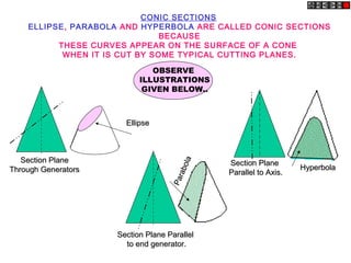
  • 1. CONIC SECTIONS ELLIPSE, PARABOLA AND HYPERBOLA ARE CALLED CONIC SECTIONS BECAUSE THESE CURVES APPEAR ON THE SURFACE OF A CONE WHEN IT IS CUT BY SOME TYPICAL CUTTING PLANES. Section PlaneSection Plane Through GeneratorsThrough Generators EllipseEllipse Section Plane ParallelSection Plane Parallel to end generator.to end generator. Parabola Parabola Section PlaneSection Plane Parallel to Axis.Parallel to Axis. HyperbolaHyperbola OBSERVE ILLUSTRATIONS GIVEN BELOW..
  • 2. These are the loci of points moving in a plane such that the ratio of it’s distances from a fixed point And a fixed line always remains constant. The Ratio is called ECCENTRICITY. (E) A) For Ellipse E<1 B) For Parabola E=1 C) For Hyperbola E>1 SECOND DEFINATION OF AN ELLIPSE:- It is a locus of a point moving in a plane such that the SUM of it’s distances from TWO fixed points always remains constant. {And this sum equals to the length of major axis.} These TWO fixed points are FOCUS 1 & FOCUS 2 Refer Problem nos. 6. 9 & 12 Refer Problem no.4 Ellipse by Arcs of Circles Method. COMMON DEFINATION OF ELLIPSE, PARABOLA & HYPERBOLA:
  • 3. 1 2 3 4 1 2 3 4 1 2 3 4 3 2 1A B C D Problem 2 Draw ellipse by Rectangle method. Take major axis 100 mm and minor axis 70 mm long. Steps: 1 Draw a rectangle taking major and minor axes as sides. 2. In this rectangle draw both axes as perpendicular bisectors of each other.. 3. For construction, select upper left part of rectangle. Divide vertical small side and horizontal long side into same number of equal parts.( here divided in four parts) 4. Name those as shown.. 5. Now join all vertical points 1,2,3,4, to the upper end of minor axis. And all horizontal points i.e.1,2,3,4 to the lower end of minor axis. 6. Then extend C-1 line upto D-1 and mark that point. Similarly extend C-2, C-3, C-4 lines up to D-2, D-3, & D-4 lines. 7. Mark all these points properly and join all along with ends A and D in smooth possible curve. Do similar construction in right side part.along with lower half of the rectangle.Join all points in smooth curve. It is required ellipse. ELLIPSE BY RECTANGLE METHOD
  • 4. C D 1 2 3 4 1 2 3 4 3 2 1A B 1 2 3 4 Problem 3:- Draw ellipse by Oblong method. Draw a parallelogram of 100 mm and 70 mm long sides with included angle of 750. Inscribe Ellipse in it. STEPS ARE SIMILAR TO THE PREVIOUS CASE (RECTANGLE METHOD) ONLY IN PLACE OF RECTANGLE, HERE IS A PARALLELOGRAM. ELLIPSE BY OBLONG METHOD
  • 5. F1 F2 1 2 3 4 A B C D p1 p2 p3 p4 ELLIPSE BY ARCS OF CIRCLE METHOD O PROBLEM 4. MAJOR AXIS AB & MINOR AXIS CD ARE 100 AMD 70MM LONG RESPECTIVELY .DRAW ELLIPSE BY ARCS OF CIRLES METHOD. STEPS: 1.Draw both axes as usual.Name the ends & intersecting point 2.Taking AO distance I.e.half major axis, from C, mark F1 & F2 On AB . ( focus 1 and 2.) 3.On line F1- O taking any distance, mark points 1,2,3, & 4 4.Taking F1 center, with distance A-1 draw an arc above AB and taking F2 center, with B-1 distance cut this arc. Name the point p1 5.Repeat this step with same centers but taking now A-2 & B-2 distances for drawing arcs. Name the point p2 6.Similarly get all other P points. With same steps positions of P can be located below AB. 7.Join all points by smooth curve to get an ellipse/ As per the definition Ellipse is locus of point P moving in a plane such that the SUM of it’s distances from two fixed points (F1 & F2) remains constant and equals to the length of major axis AB.(Note A .1+ B .1=A . 2 + B. 2 = AB)
  • 6. FOR FULL SIZE SCALE R.F.=1 OR ( 1:1 ) MEANS DRAWING & OBJECT ARE OF SAME SIZE. Other RFs are described as 1:10, 1:100, 1:1000, 1:1,00,000 SCALES DIMENSIONS OF LARGE OBJECTS MUST BE REDUCED TO ACCOMMODATE ON STANDARD SIZE DRAWING SHEET.THIS REDUCTION CREATES A SCALE OF THAT REDUCTION RATIO, WHICH IS GENERALLY A FRACTION.. SUCH A SCALE IS CALLED REDUCING SCALE AND THAT RATIO IS CALLED REPRESENTATIVE FACTOR. SIMILARLY IN CASE OF TINY OBJECTS DIMENSIONS MUST BE INCREASED FOR ABOVE PURPOSE. HENCE THIS SCALE IS CALLED ENLARGING SCALE. HERE THE RATIO CALLED REPRESENTATIVE FACTOR IS MORE THAN UNITY. REPRESENTATIVE FACTOR (R.F.) = = = = A USE FOLLOWING FORMULAS FOR THE CALCULATIONS IN THIS TOPIC. B LENGTH OF SCALE = R.F. MAX. LENGTH TO BE MEASURED.X DIMENSION OF DRAWING DIMENSION OF OBJECT LENGTH OF DRAWING ACTUAL LENGTH AREA OF DRAWING ACTUAL AREA VOLUME AS PER DRWG. ACTUAL VOLUME V V 3
  • 7. 1. PLAIN SCALES ( FOR DIMENSIONS UP TO SINGLE DECIMAL) 2. DIAGONAL SCALES ( FOR DIMENSIONS UP TO TWO DECIMALS) 3. VERNIER SCALES ( FOR DIMENSIONS UP TO TWO DECIMALS) 4. COMPARATIVE SCALES ( FOR COMPARING TWO DIFFERENT UNITS) 5. SCALE OF CORDS ( FOR MEASURING/CONSTRUCTING ANGLES) TYPES OF SCALES: = 10 HECTOMETRES = 10 DECAMETRES = 10 METRES = 10 DECIMETRES = 10 CENTIMETRES = 10 MILIMETRES 1 KILOMETRE 1 HECTOMETRE 1 DECAMETRE 1 METRE 1 DECIMETRE 1 CENTIMETRE BE FRIENDLY WITH THESE UNITS.
  • 8. 0 1 2 3 4 510 PLAIN SCALE:-This type of scale represents two units or a unit and it’s sub-division. METERS DECIMETERS R.F. = 1/100 4 M 6 DM PLANE SCALE SHOWING METERS AND DECIMETERS. PLAIN SCALE PROBLEM NO.1:- Draw a scale 1 cm = 1m to read decimeters, to measure maximum distance of 6 m. Show on it a distance of 4 m and 6 dm. CONSTRUCTION:- a) Calculate R.F.= R.F.= 1cm/ 1m = 1/100 Length of scale = R.F. X max. distance = 1/100 X 600 cm = 6 cms b) Draw a line 6 cm long and divide it in 6 equal parts. Each part will represent larger division unit. c) Sub divide the first part which will represent second unit or fraction of first unit. d) Place ( 0 ) at the end of first unit. Number the units on right side of Zero and subdivisions on left-hand side of Zero. Take height of scale 5 to 10 mm for getting a look of scale. e) After construction of scale mention it’s RF and name of scale as shown. f) Show the distance 4 m 6 dm on it as shown. DIMENSION OF DRAWING DIMENSION OF OBJECT
  • 9. PROBLEM NO.2:- In a map a 36 km distance is shown by a line 45 cms long. Calculate the R.F. and construct a plain scale to read kilometers and hectometers, for max. 12 km. Show a distance of 8.3 km on it. CONSTRUCTION:- a) Calculate R.F. R.F.= 45 cm/ 36 km = 45/ 36 . 1000 . 100 = 1/ 80,000 Length of scale = R.F. max. distance = 1/ 80000 12 km = 15 cm b) Draw a line 15 cm long and divide it in 12 equal parts. Each part will represent larger division unit. c) Sub divide the first part which will represent second unit or fraction of first unit. d) Place ( 0 ) at the end of first unit. Number the units on right side of Zero and subdivisions on left-hand side of Zero. Take height of scale 5 to 10 mm for getting a look of scale. e) After construction of scale mention it’s RF and name of scale as shown. f) Show the distance 8.3 km on it as shown. KILOMETERS HECTOMETERS 8KM 3HM R.F. = 1/80,000 PLANE SCALE SHOWING KILOMETERS AND HECTOMETERS 0 1 2 3 4 5 6 7 8 9 10 1110 5 PLAIN SCALE
  • 10. PROBLEM NO.3:- The distance between two stations is 210 km. A passenger train covers this distance in 7 hours. Construct a plain scale to measure time up to a single minute. RF is 1/200,000 Indicate the distance traveled by train in 29 minutes. CONSTRUCTION:- a) 210 km in 7 hours. Means speed of the train is 30 km per hour ( 60 minutes) Length of scale = R.F. max. distance per hour = 1/ 2,00,000 30km = 15 cm b) 15 cm length will represent 30 km and 1 hour i.e. 60 minutes. Draw a line 15 cm long and divide it in 6 equal parts. Each part will represent 5 km and 10 minutes. c) Sub divide the first part in 10 equal parts,which will represent second unit or fraction of first unit. Each smaller part will represent distance traveled in one minute. d) Place ( 0 ) at the end of first unit. Number the units on right side of Zero and subdivisions on left-hand side of Zero. Take height of scale 5 to 10 mm for getting a proper look of scale. e) Show km on upper side and time in minutes on lower side of the scale as shown. After construction of scale mention it’s RF and name of scale as shown. f) Show the distance traveled in 29 minutes, which is 14.5 km, on it as shown. PLAIN SCALE 0 10 20 30 40 5010 MINUTESMIN R.F. = 1/100 PLANE SCALE SHOWING METERS AND DECIMETERS. KMKM 0 5 10 15 20 255 2.5 DISTANCE TRAVELED IN 29 MINUTES. 14.5 KM
  • 11. We have seen that the plain scales give only two dimensions, such as a unit and it’s subunit or it’s fraction. 1 2 3 4 5 6 7 8 9 10 1’ 2’ 3’ 4’ 5’ 6’ 7’ 8’ 9’ 10’ X Y Z The principle of construction of a diagonal scale is as follows. Let the XY in figure be a subunit. From Y draw a perpendicular YZ to a suitable height. Join XZ. Divide YZ in to 10 equal parts. Draw parallel lines to XY from all these divisions and number them as shown. From geometry we know that similar triangles have their like sides proportional. Consider two similar triangles XYZ and 7’ 7Z, we have 7Z / YZ = 7’7 / XY (each part being one unit) Means 7’ 7 = 7 / 10. x X Y = 0.7 XY :. Similarly 1’ – 1 = 0.1 XY 2’ – 2 = 0.2 XY Thus, it is very clear that, the sides of small triangles, which are parallel to divided lines, become progressively shorter in length by 0.1 XY. The solved examples ON NEXT PAGES will make the principles of diagonal scales clear. The diagonal scales give us three successive dimensions that is a unit, a subunit and a subdivision of a subunit. DIAGONAL SCALE
  • 12. R.F. = 1 / 40,00,000 DIAGONAL SCALE SHOWING KILOMETERS. 0 100 200 300 400 500100 50 10 9 8 7 6 5 4 3 2 1 0 KM KM KM 569 km 459 km 336 km 222 km PROBLEM NO. 4 : The distance between Delhi and Agra is 200 km. In a railway map it is represented by a line 5 cm long. Find it’s R.F. Draw a diagonal scale to show single km. And maximum 600 km. Indicate on it following distances. 1) 222 km 2) 336 km 3) 459 km 4) 569 km SOLUTION STEPS: RF = 5 cm / 200 km = 1 / 40, 00, 000 Length of scale = 1 / 40, 00, 000 X 600 X 105 = 15 cm Draw a line 15 cm long. It will represent 600 km.Divide it in six equal parts.( each will represent 100 km.) Divide first division in ten equal parts.Each will represent 10 km.Draw a line upward from left end and mark 10 parts on it of any distance. Name those parts 0 to 10 as shown.Join 9th sub-division of horizontal scale with 10th division of the vertical divisions. Then draw parallel lines to this line from remaining sub divisions and complete diagonal scale. DIAGONAL SCALE
  • 13. PROBLEM NO.5: A rectangular plot of land measuring 1.28 hectors is represented on a map by a similar rectangle of 8 sq. cm. Calculate RF of the scale. Draw a diagonal scale to read single meter. Show a distance of 438 m on it. Draw a line 15 cm long. It will represent 600 m.Divide it in six equal parts. ( each will represent 100 m.) Divide first division in ten equal parts.Each will represent 10 m. Draw a line upward from left end and mark 10 parts on it of any distance. Name those parts 0 to 10 as shown.Join 9th sub-division of horizontal scale with 10th division of the vertical divisions. Then draw parallel lines to this line from remaining sub divisions and complete diagonal scale. DIAGONAL SCALE SOLUTION : 1 hector = 10, 000 sq. meters 1.28 hectors = 1.28 X 10, 000 sq. meters = 1.28 X 104 X 104 sq. cm 8 sq. cm area on map represents = 1.28 X 104 X 104 sq. cm on land 1 cm sq. on map represents = 1.28 X 10 4 X 10⁴ / 8 sq cm on land 1 cm on map represent = 1.28 X 104 X 104 / 8 cm = 4, 000 cm 1 cm on drawing represent 4, 000 cm, Means RF = 1 / 4000 Assuming length of scale 15 cm, it will represent 600 m. 0 100 200 300 400 500100 50 10 9 8 7 6 5 4 3 2 1 0 M M M 438 meters R.F. = 1 / 4000 DIAGONAL SCALE SHOWING METERS.
  • 14. 10 9 8 7 6 5 4 3 2 1 0 CENTIMETRES MM CM R.F. = 1 / 2.5 DIAGONAL SCALE SHOWING CENTIMETERS. 0 5 10 155 4 3 2 1 PROBLEM NO.6:. Draw a diagonal scale of R.F. 1: 2.5, showing centimeters and millimeters and long enough to measure up to 20 centimeters. SOLUTION STEPS: R.F. = 1 / 2.5 Length of scale = 1 / 2.5 X 20 cm. = 8 cm. 1.Draw a line 8 cm long and divide it in to 4 equal parts. (Each part will represent a length of 5 cm.) 2.Divide the first part into 5 equal divisions. (Each will show 1 cm.) 3.At the left hand end of the line, draw a vertical line and on it step-off 10 equal divisions of any length. 4.Complete the scale as explained in previous problems. Show the distance 13.4 cm on it. 13 .4 CM DIAGONAL SCALE
  • 15. Figure to the right shows a part of a plain scale in which length A-O represents 10 cm. If we divide A-O into ten equal parts, each will be of 1 cm. Now it would not be easy to divide each of these parts into ten equal divisions to get measurements in millimeters. Now if we take a length BO equal to 10 + 1 = 11 such equal parts, thus representing 11 cm, and divide it into ten equal divisions, each of these divisions will represent 11 / 10 – 1.1 cm. The difference between one part of AO and one division of BO will be equal 1.1 – 1.0 = 0.1 cm or 1 mm. This difference is called Least Count of the scale. Minimum this distance can be measured by this scale. The upper scale BO is the vernier.The combination of plain scale and the vernier is vernier scale. Vernier Scales: These scales, like diagonal scales , are used to read to a very small unit with great accuracy. It consists of two parts – a primary scale and a vernier. The primary scale is a plain scale fully divided into minor divisions. As it would be difficult to sub-divide the minor divisions in ordinary way, it is done with the help of the vernier. The graduations on vernier are derived from those on the primary scale. 9.9 7.7 5.5 3.3 1.1 9 8 7 6 5 4 3 2 1 0A 0B
  • 16. Example 10: Draw a vernier scale of RF = 1 / 25 to read centimeters upto 4 meters and on it, show lengths 2.39 m and 0.91 m .9 .8 .7 .6 .5 .4 .3 .2 .1 .99 .77 .55 .33 .11 01.1 0 1 2 31.0 SOLUTION: Length of scale = RF X max. Distance = 1 / 25 X 4 X 100 = 16 cm CONSTRUCTION: ( Main scale) Draw a line 16 cm long. Divide it in 4 equal parts. ( each will represent meter ) Sub-divide each part in 10 equal parts. ( each will represent decimeter ) Name those properly. CONSTRUCTION: ( vernier) Take 11 parts of Dm length and divide it in 10 equal parts. Each will show 0.11 m or 1.1 dm or 11 cm and construct a rectangle Covering these parts of vernier. TO MEASURE GIVEN LENGTHS: (1) For 2.39 m : Subtract 0.99 from 2.39 i.e. 2.39 - .99 = 1.4 m The distance between 0.99 ( left of Zero) and 1.4 (right of Zero) is 2.39 m (2) For 0.91 m : Subtract 0.11 from 0.91 i.e. 0.91 – 0.11 =0.80 m The distance between 0.11 and 0.80 (both left side of Zero) is 0.91 m 1.4 2.39 m 0.91 m METERS METERS Vernier Scale
  • 17. Example 11: A map of size 500cm X 50cm wide represents an area of 6250 sq.Kms. Construct a vernier scaleto measure kilometers, hectometers and decameters and long enough to measure upto 7 km. Indicate on it a) 5.33 km b) 59 decameters. Vernier Scale SOLUTION: RF = = = 2 / 105 Length of scale = RF X max. Distance = 2 / 105 X 7 kms = 14 cm AREA OF DRAWING ACTUAL AREAV 500 X 50 cm sq. 6250 km sq.V CONSTRUCTION: ( vernier) Take 11 parts of hectometer part length and divide it in 10 equal parts. Each will show 1.1 hm m or 11 dm and Covering in a rectangle complete scale. CONSTRUCTION: ( Main scale) Draw a line 14 cm long. Divide it in 7 equal parts. ( each will represent km ) Sub-divide each part in 10 equal parts. ( each will represent hectometer ) Name those properly. KILOMETERSHECTOMETERS 0 1 2 310 4 5 6 90 70 50 30 10 99 77 55 33 11 Decameters TO MEASURE GIVEN LENGTHS: a) For 5.33 km : Subtract 0.33 from 5.33 i.e. 5.33 - 0.33 = 5.00 The distance between 33 dm ( left of Zero) and 5.00 (right of Zero) is 5.33 k m (b) For 59 dm : Subtract 0.99 from 0.59 i.e. 0.59 – 0.99 = - 0.4 km ( - ve sign means left of Zero) The distance between 99 dm and - .4 km is 59 dm (both left side of Zero) 5.33 km59 dm