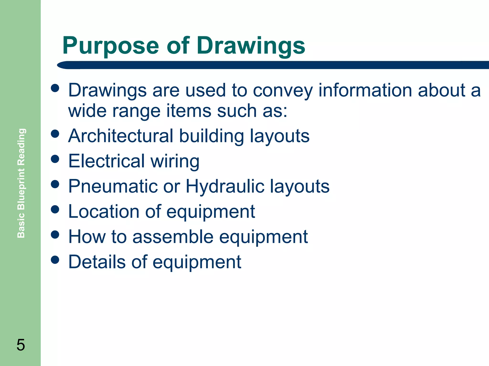
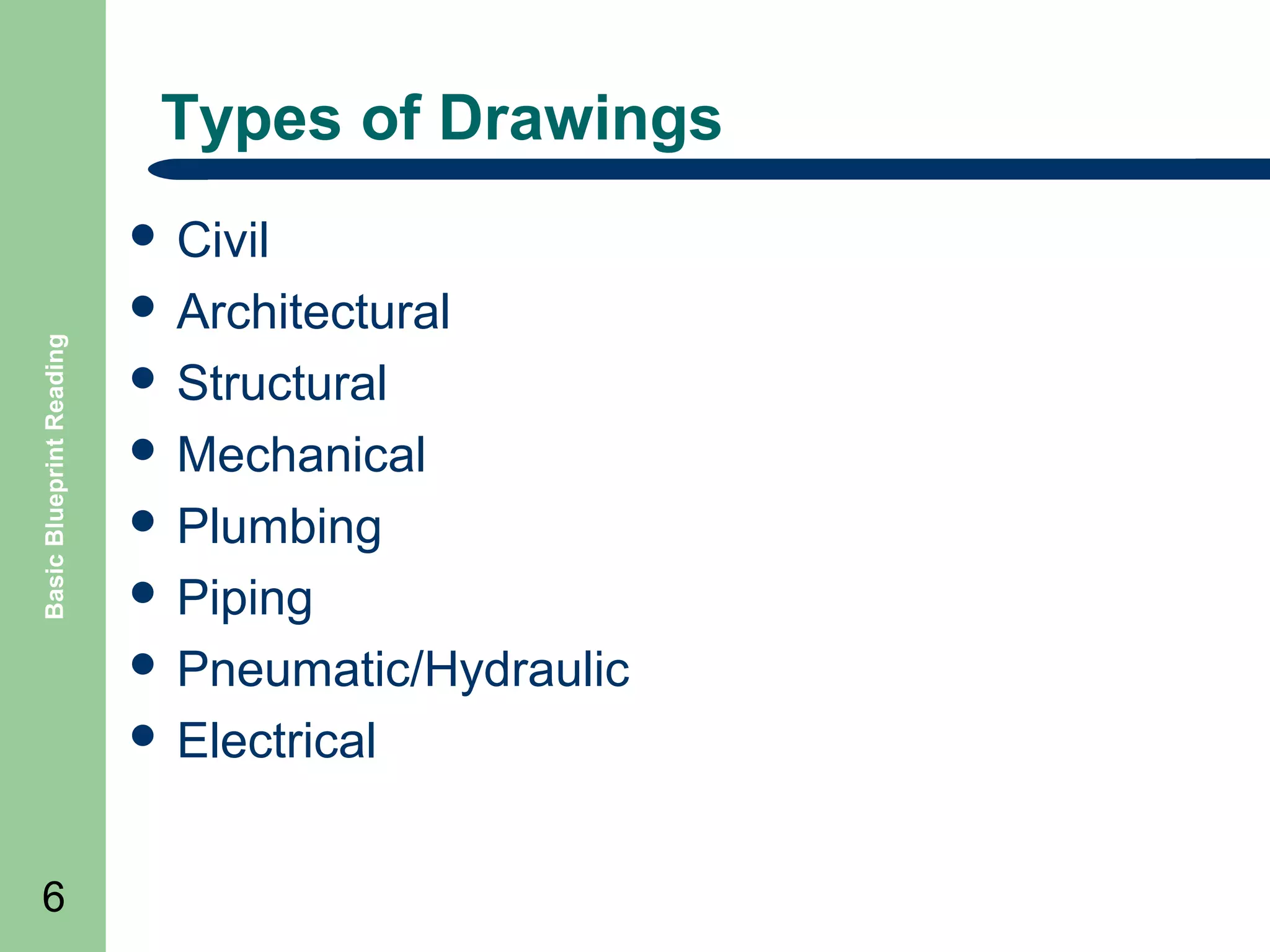
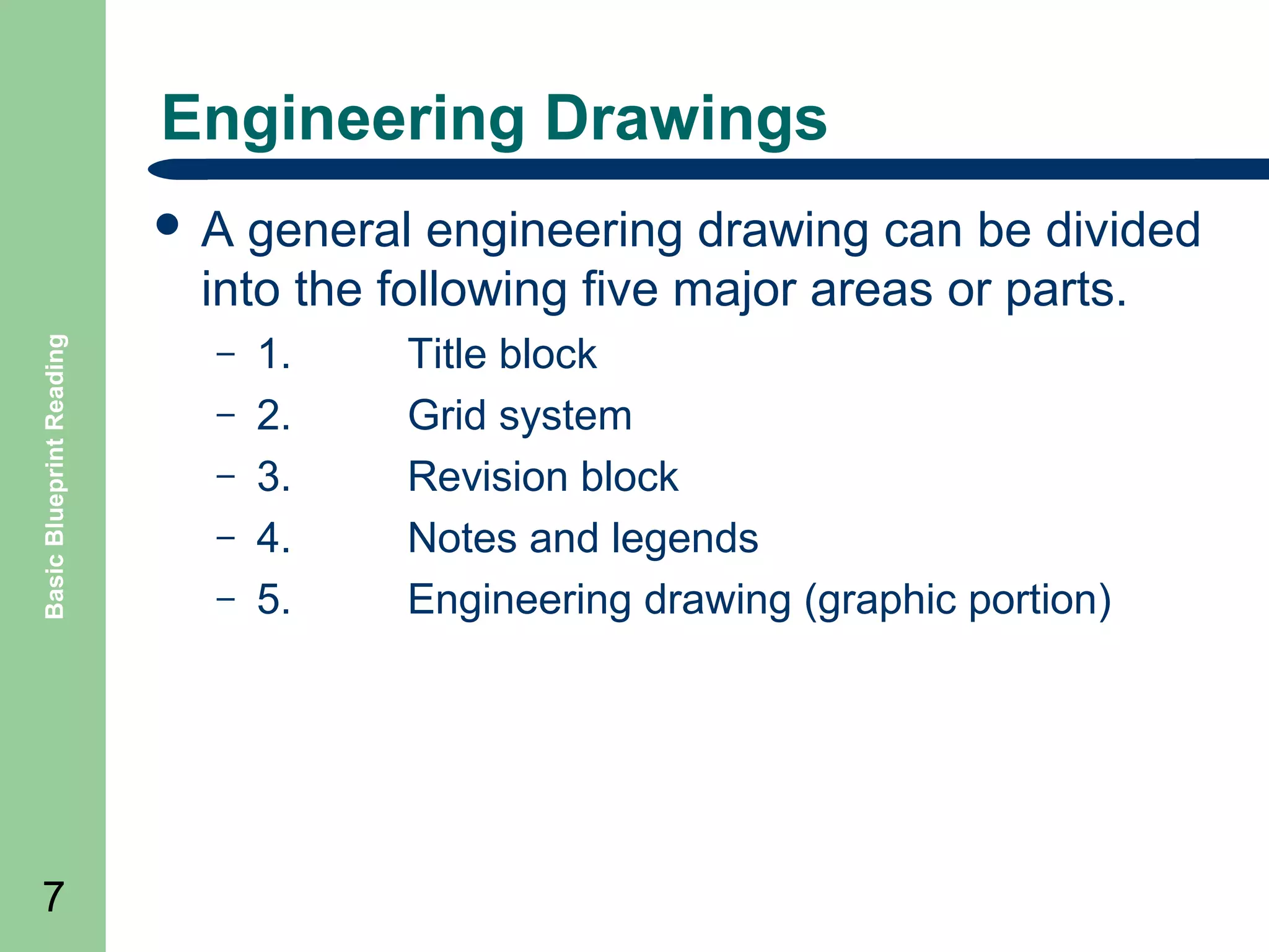
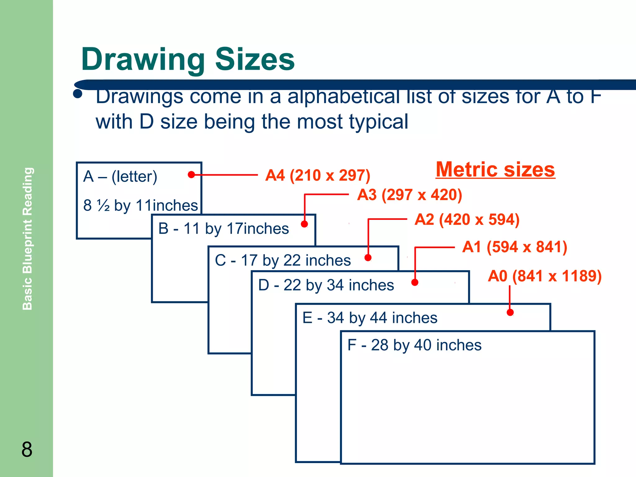
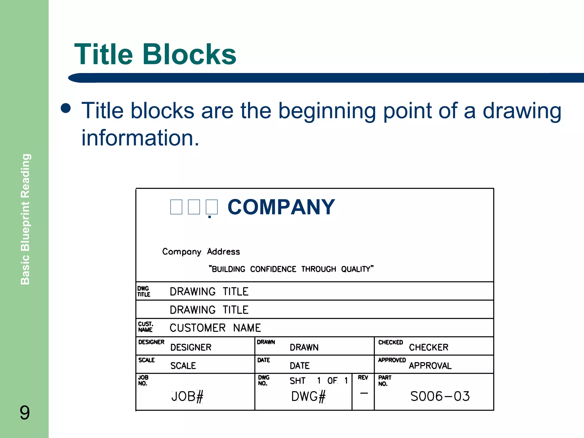
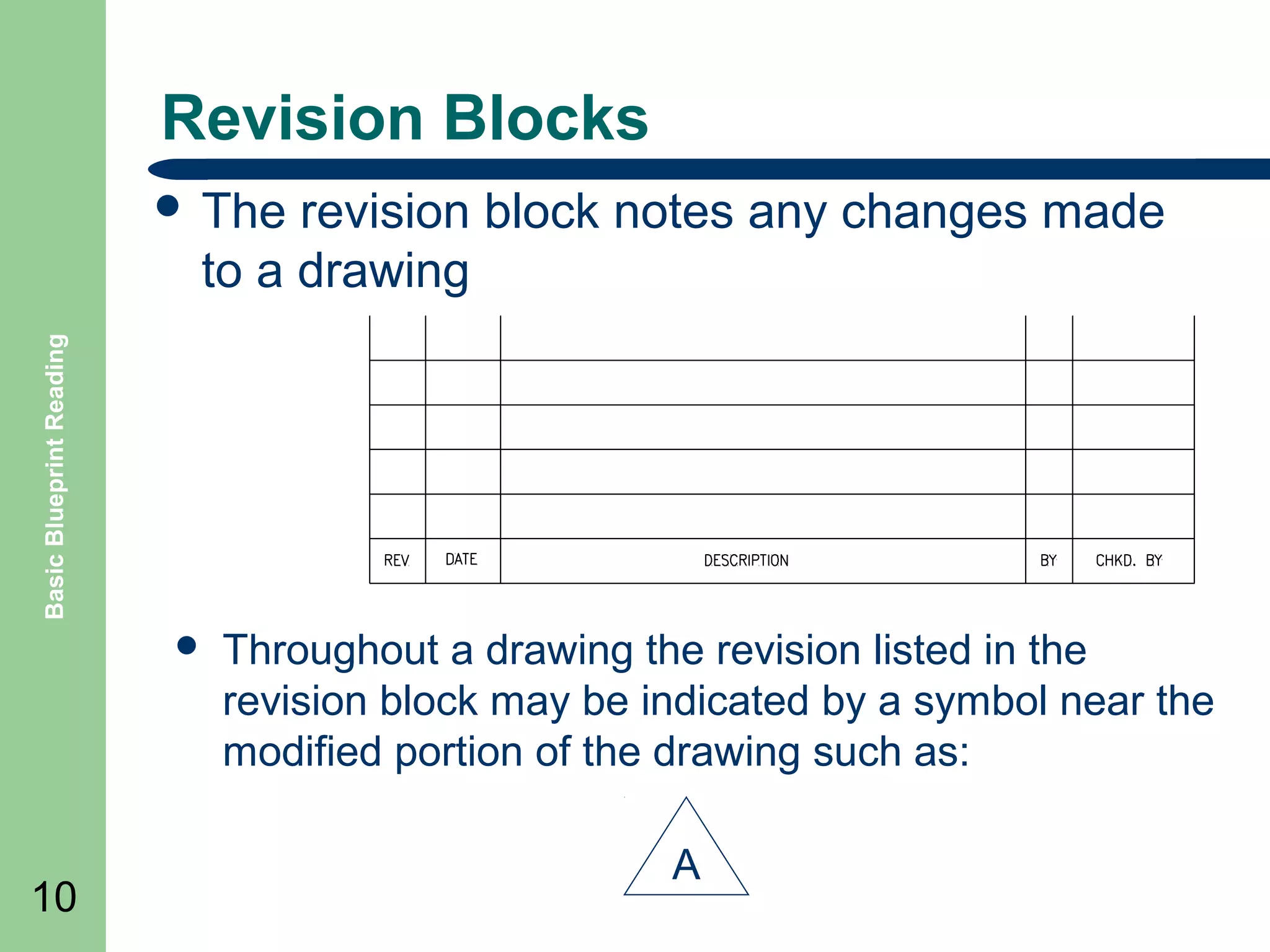
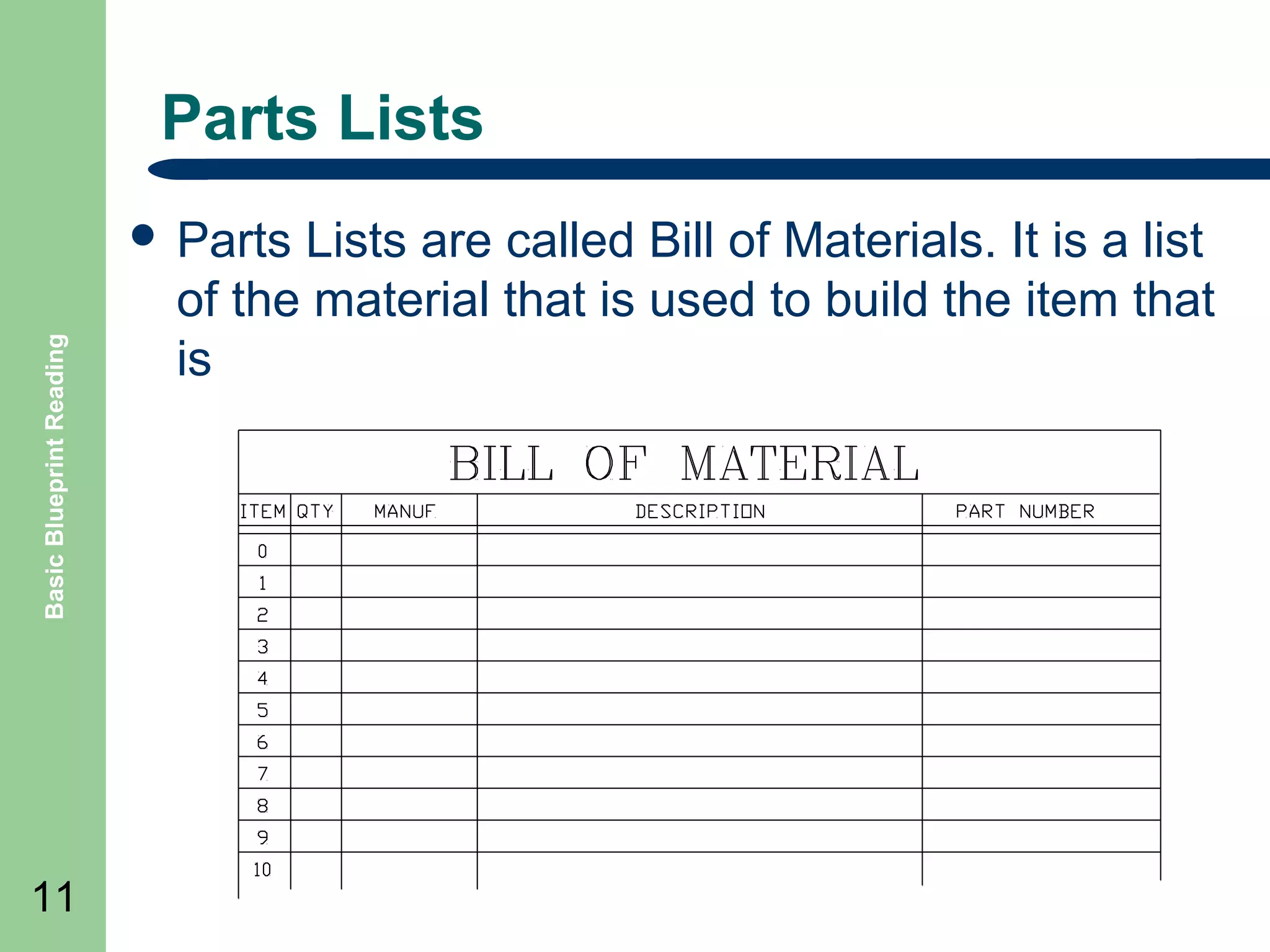
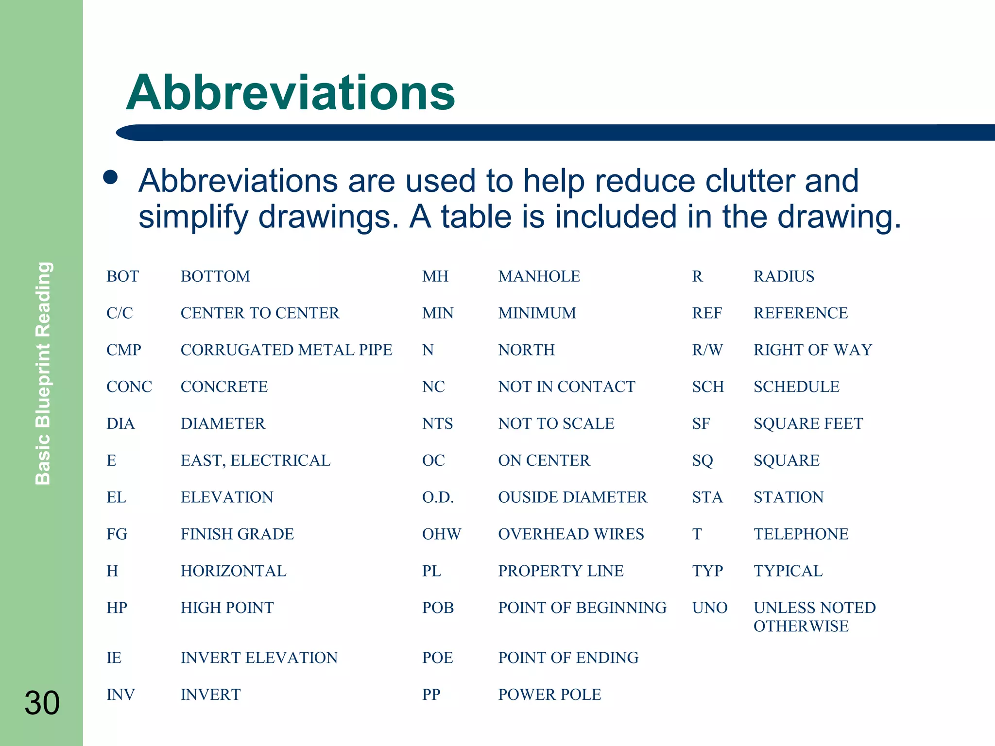
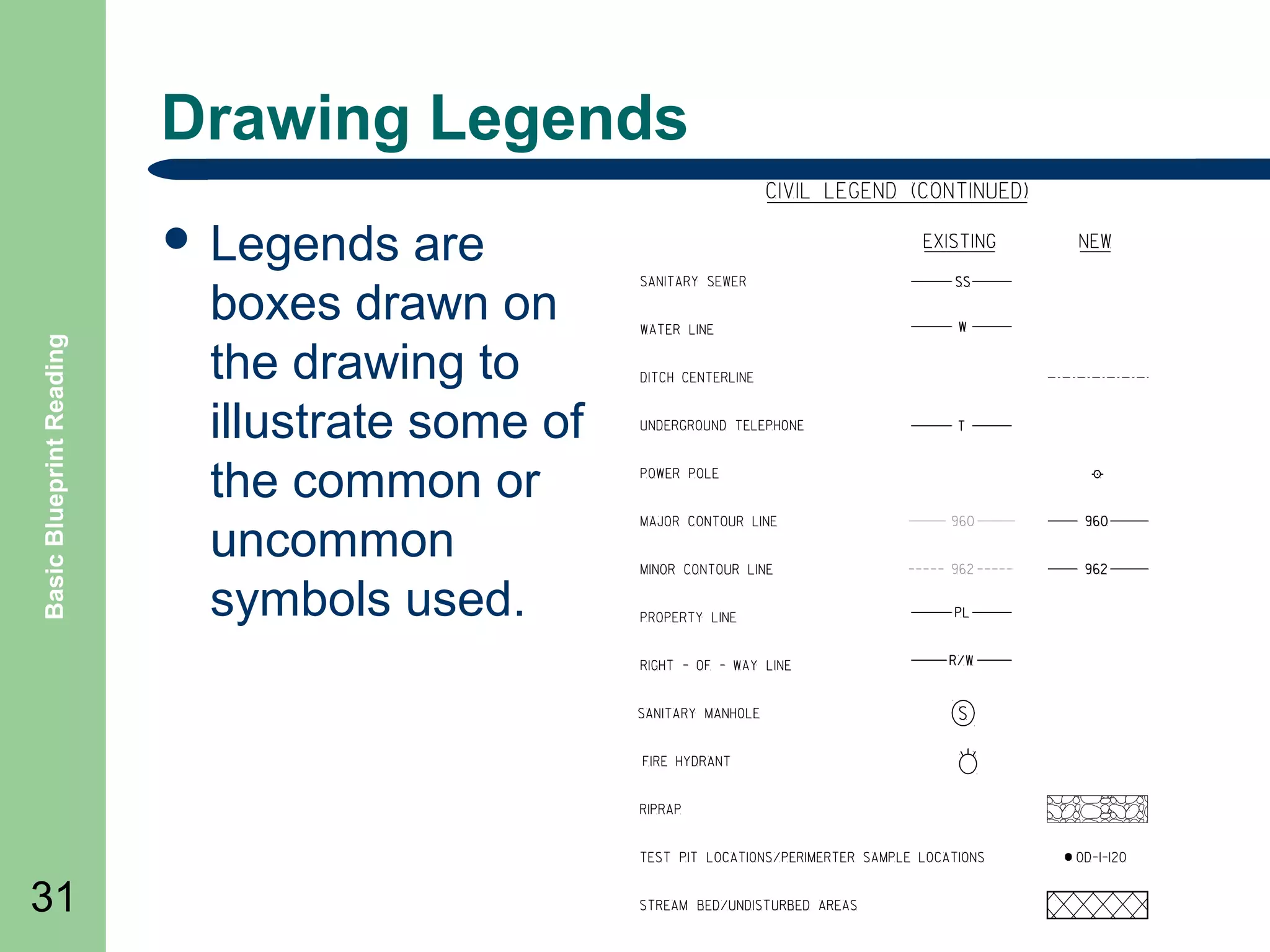
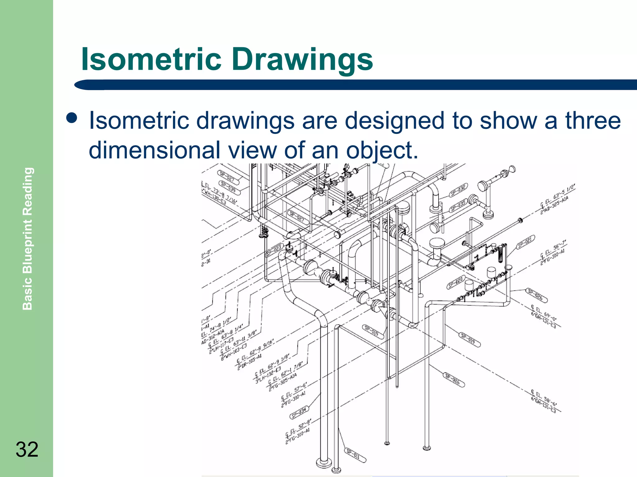
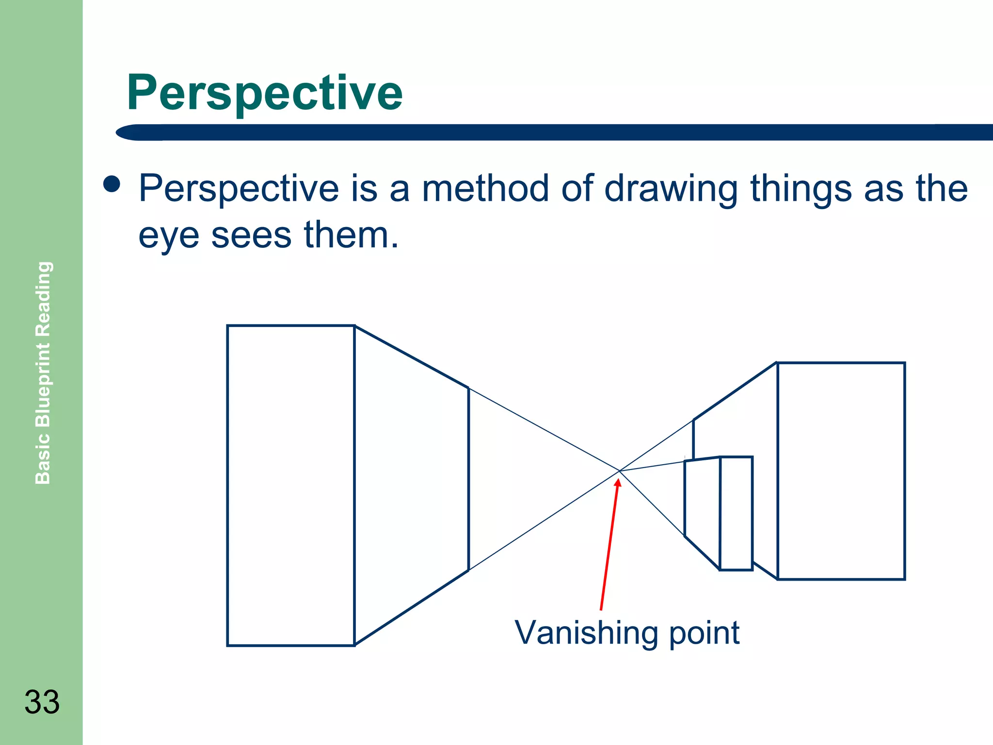
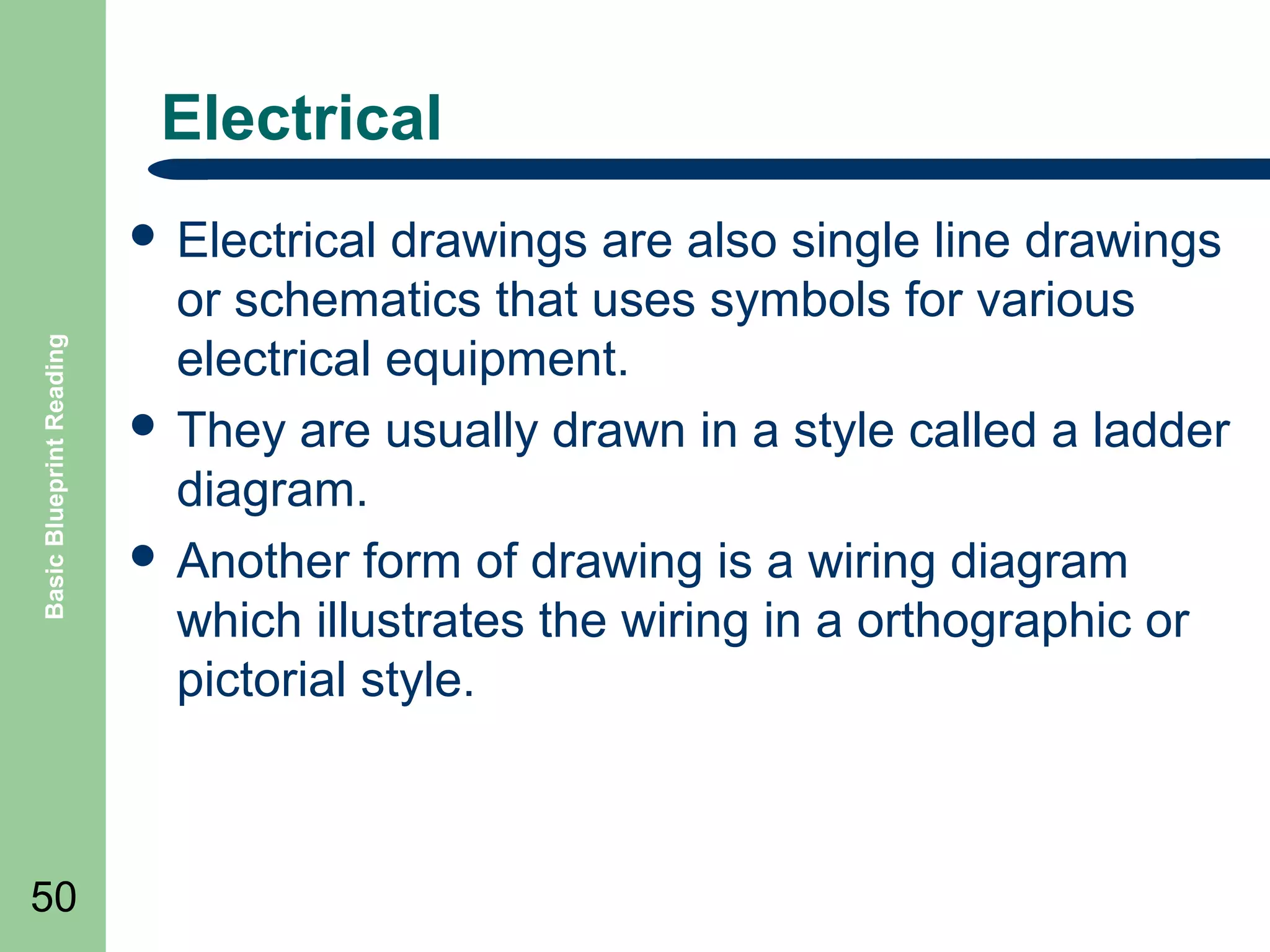
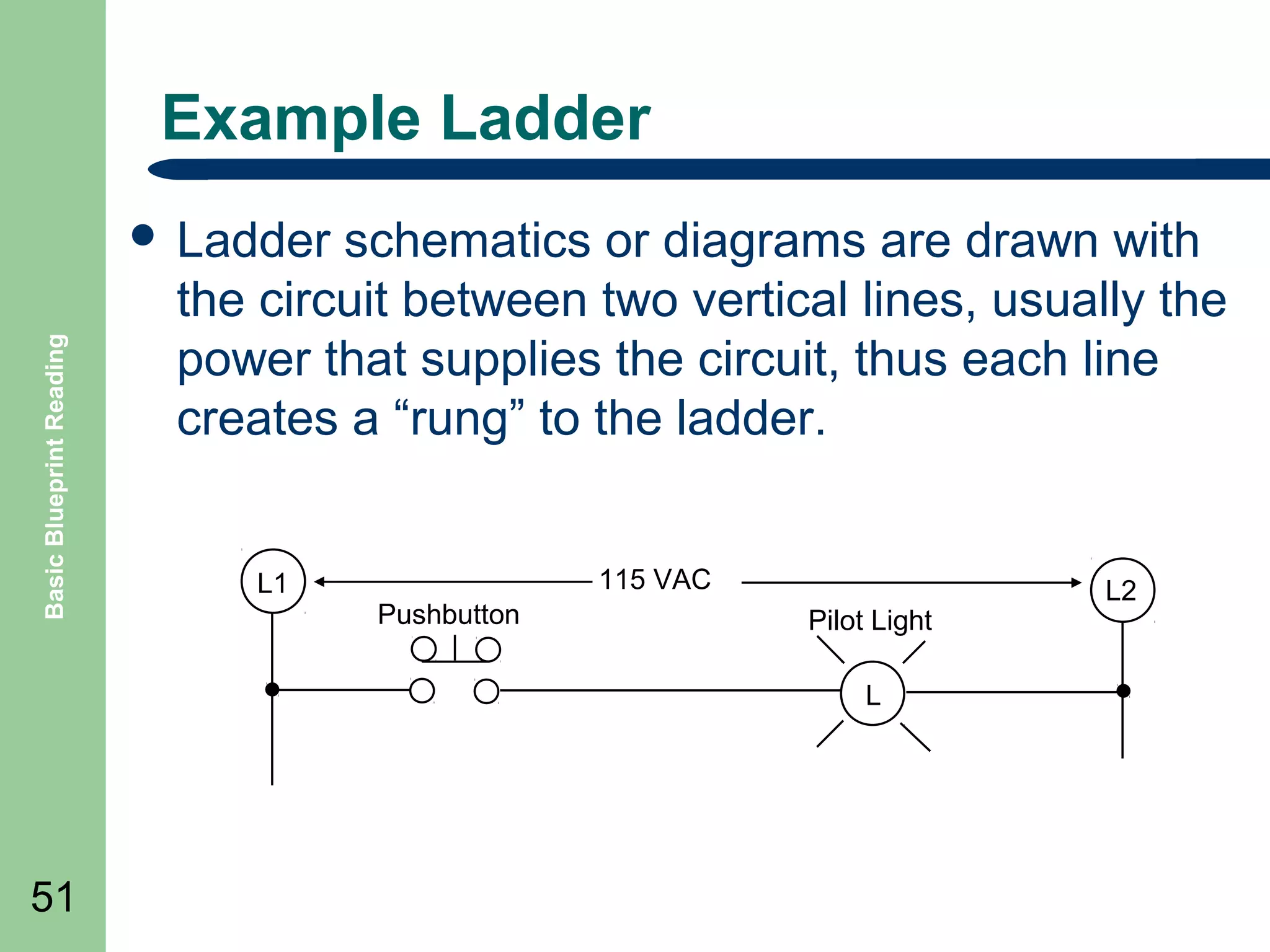
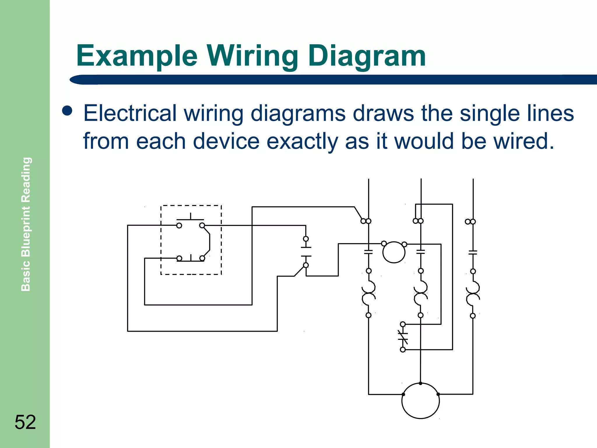
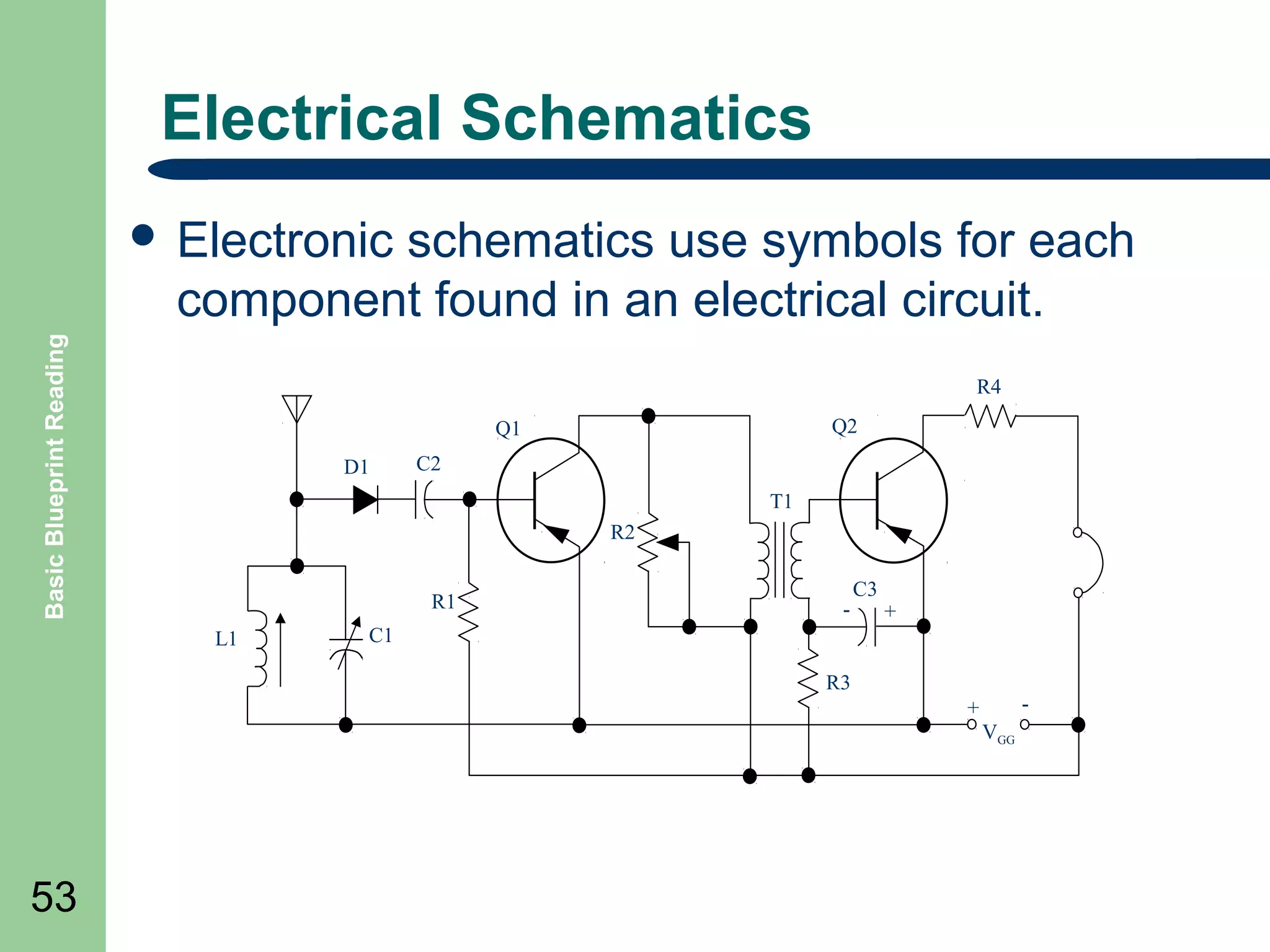
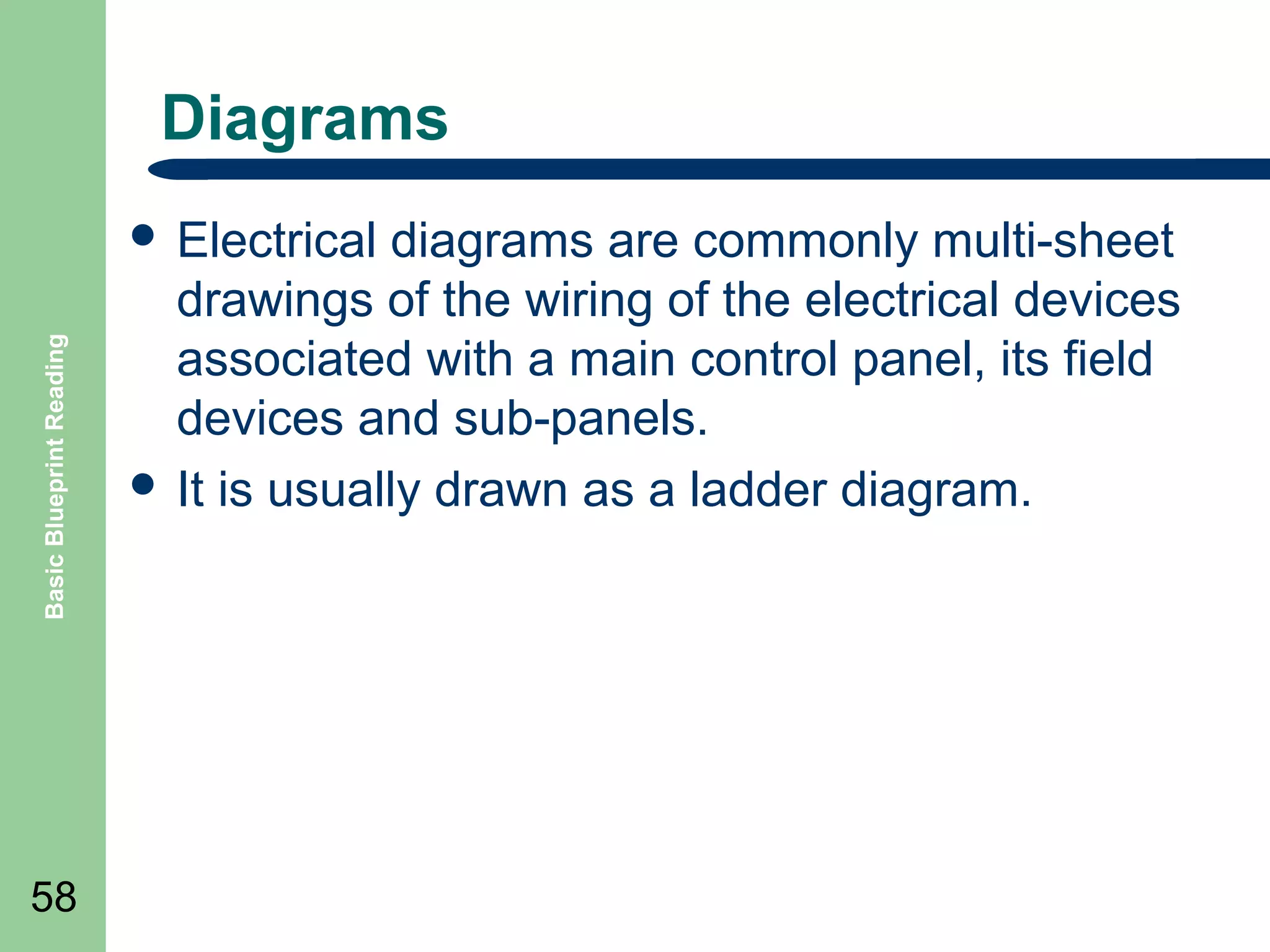
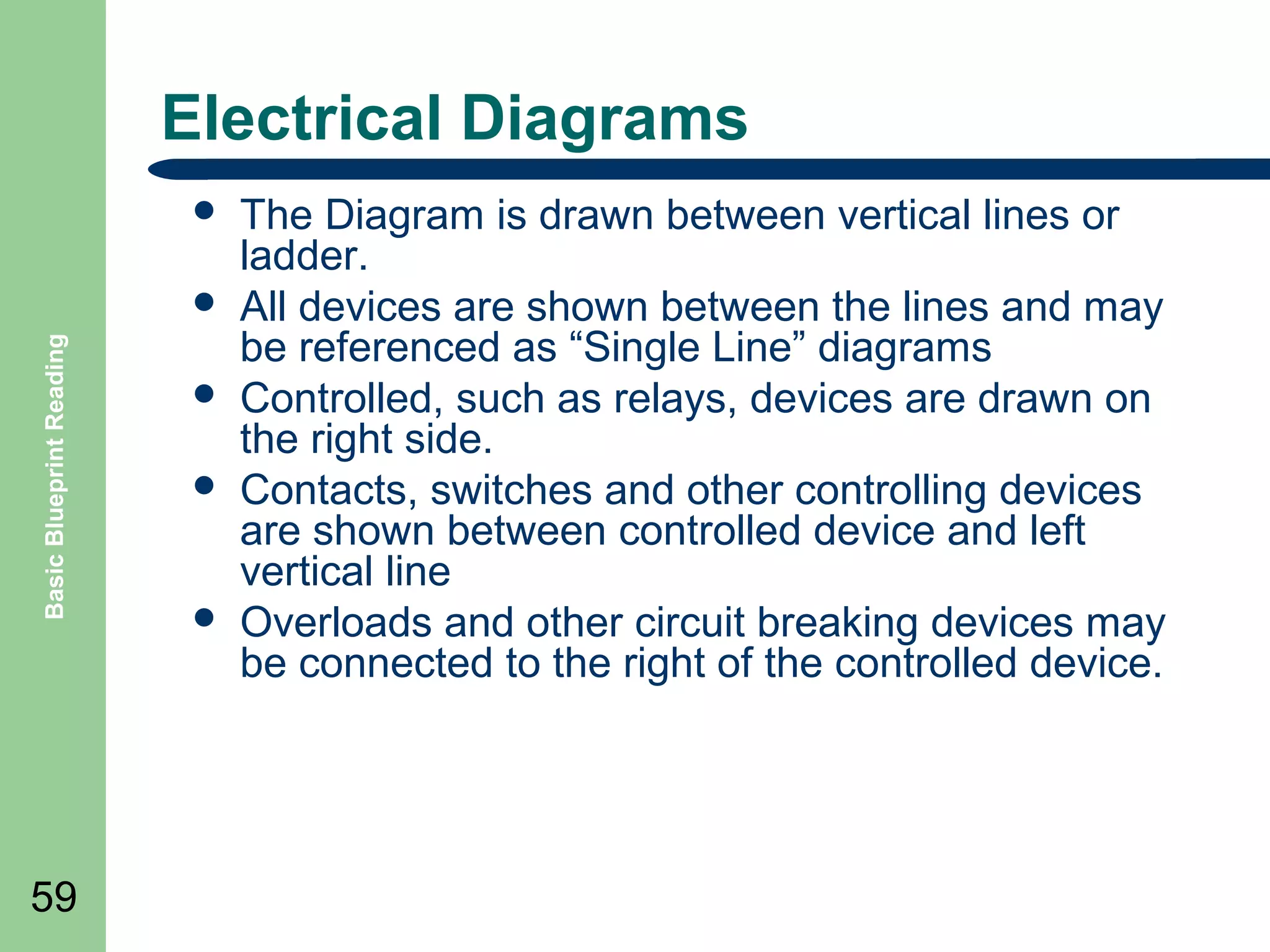
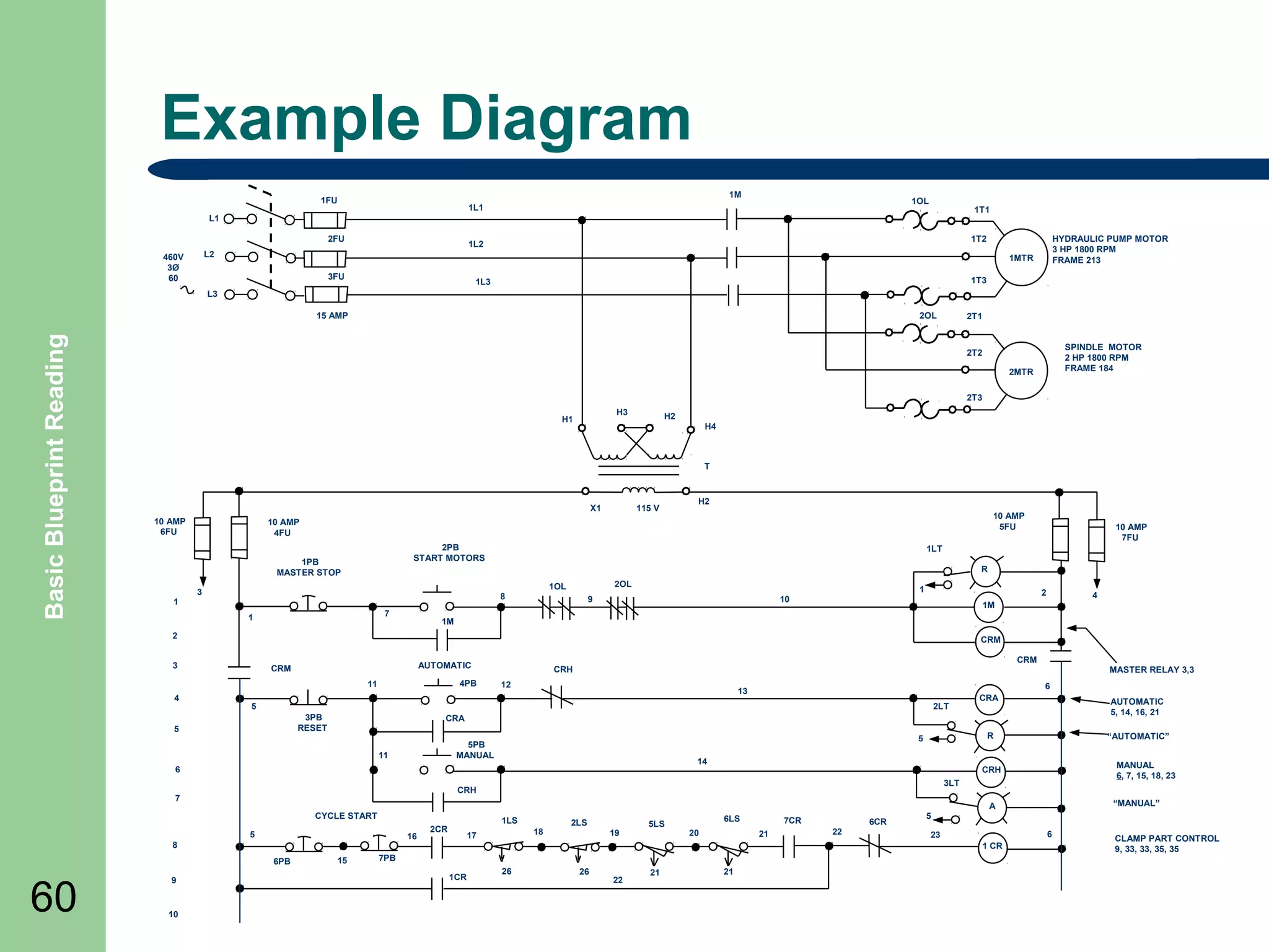
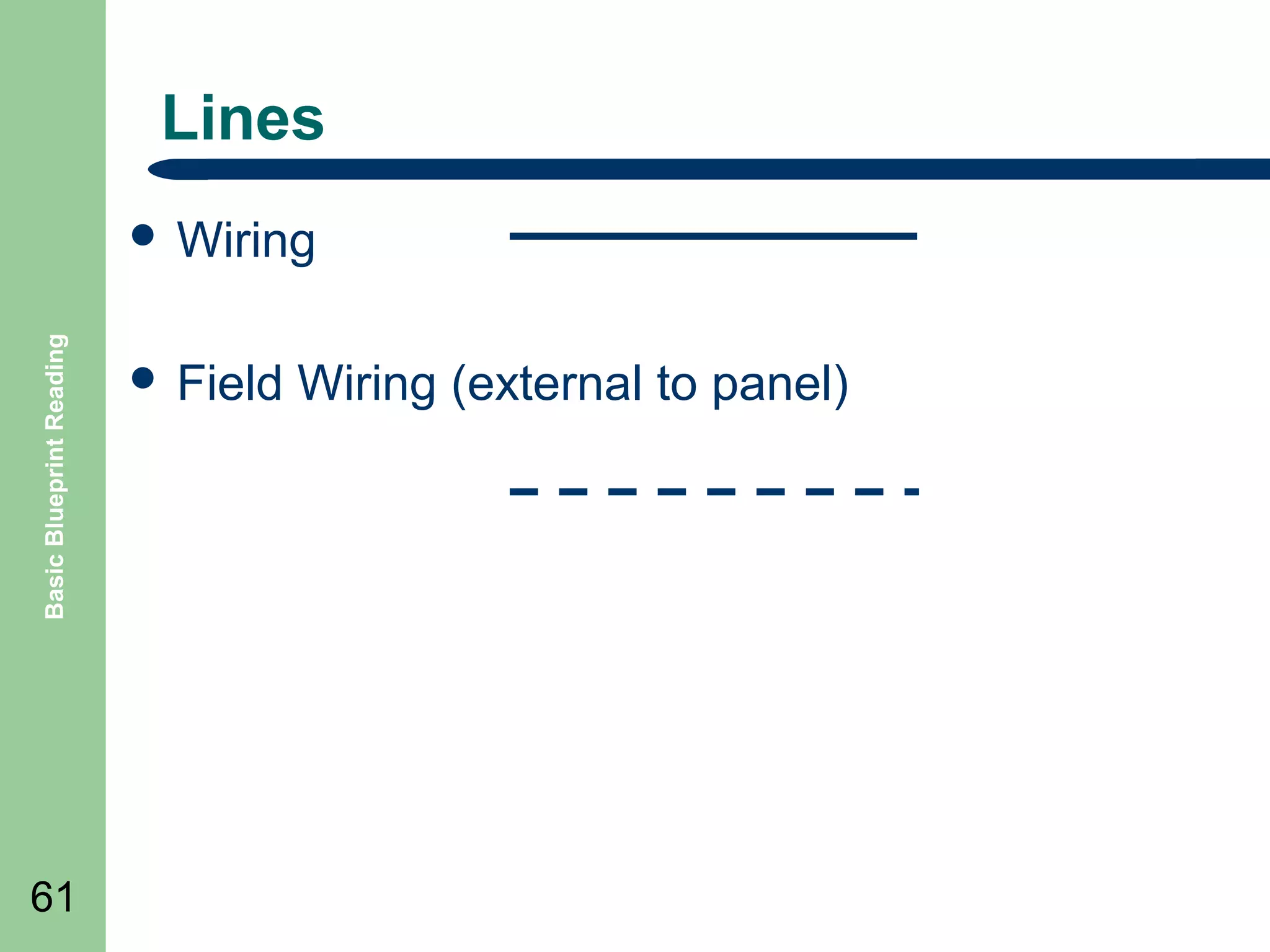
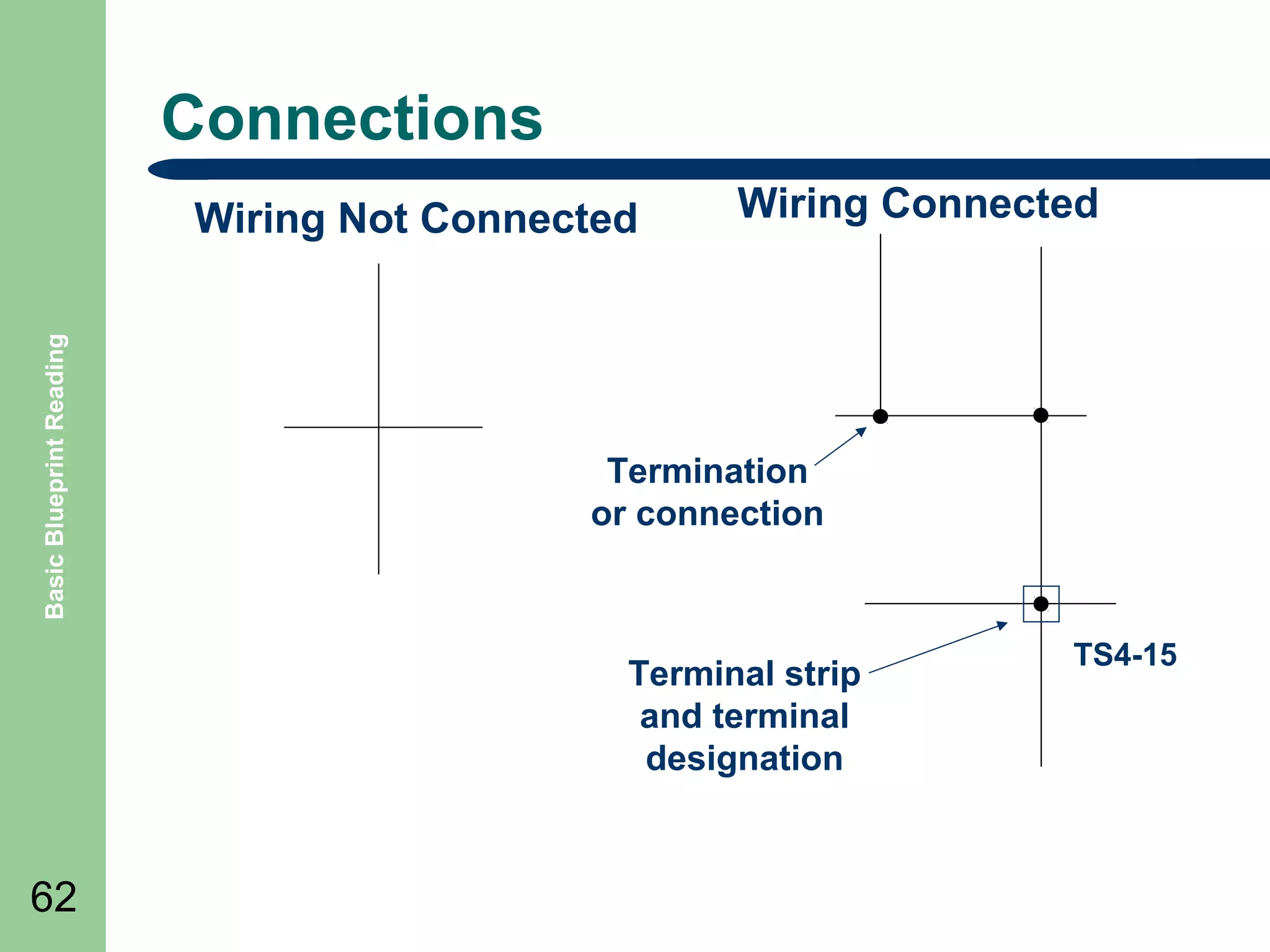
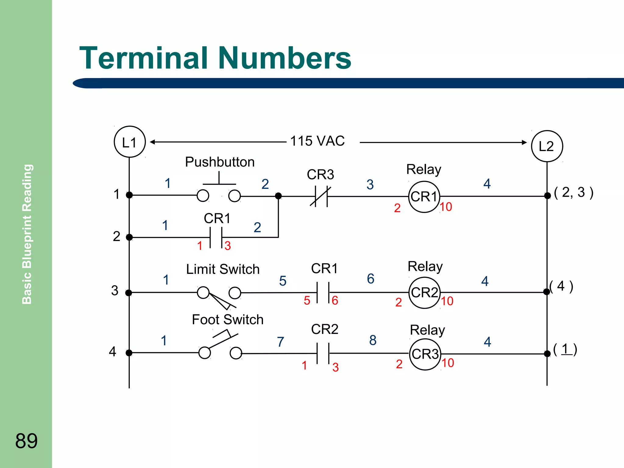
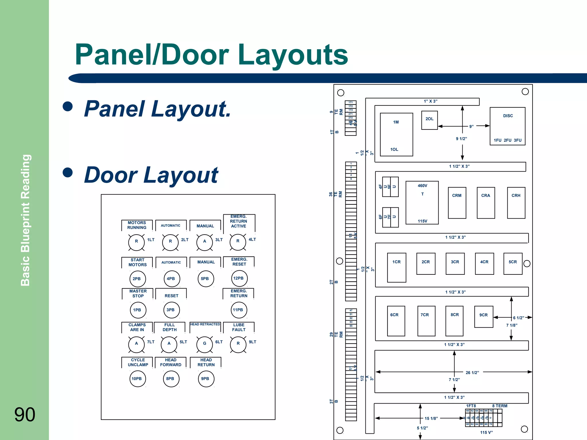
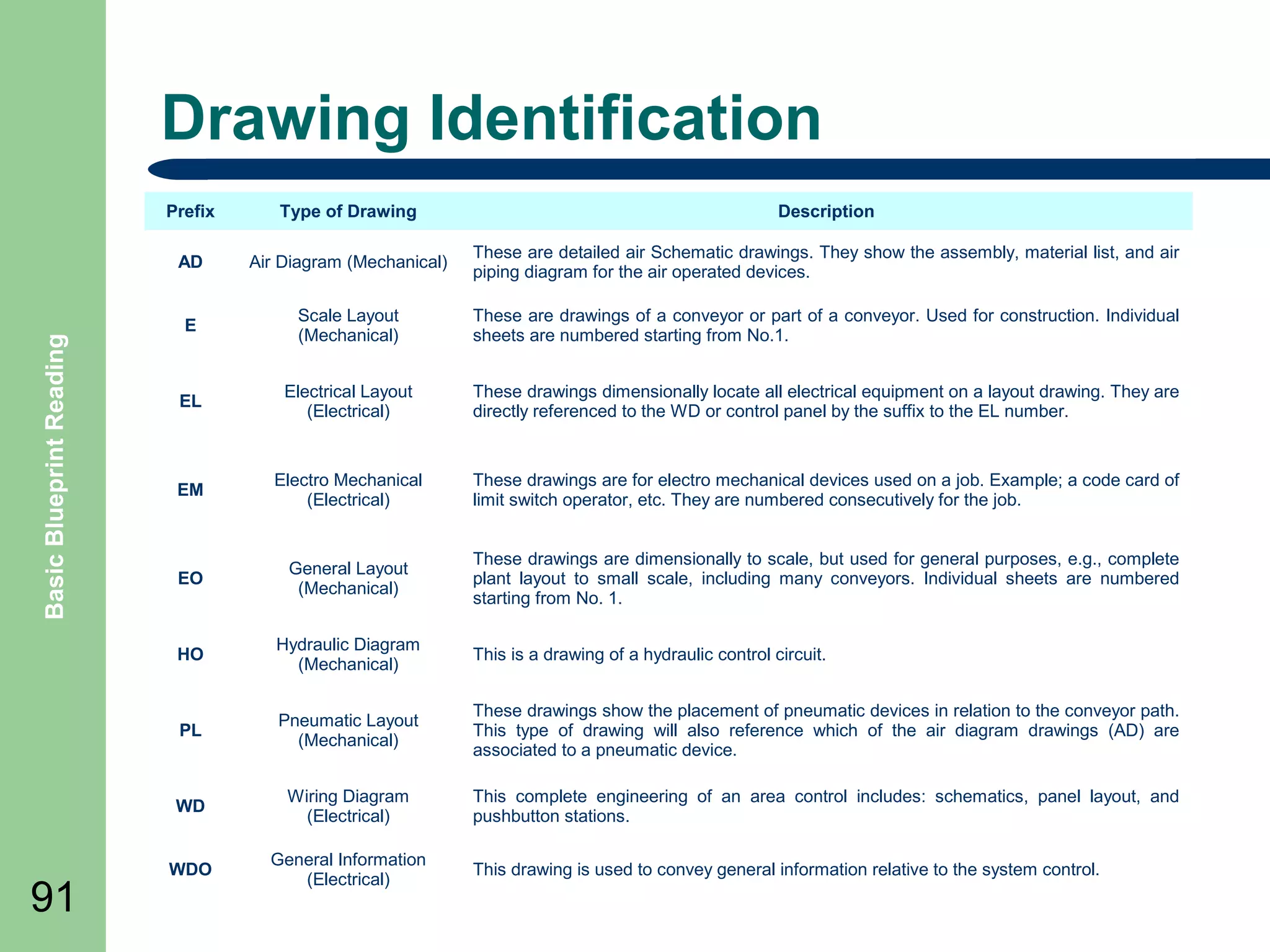
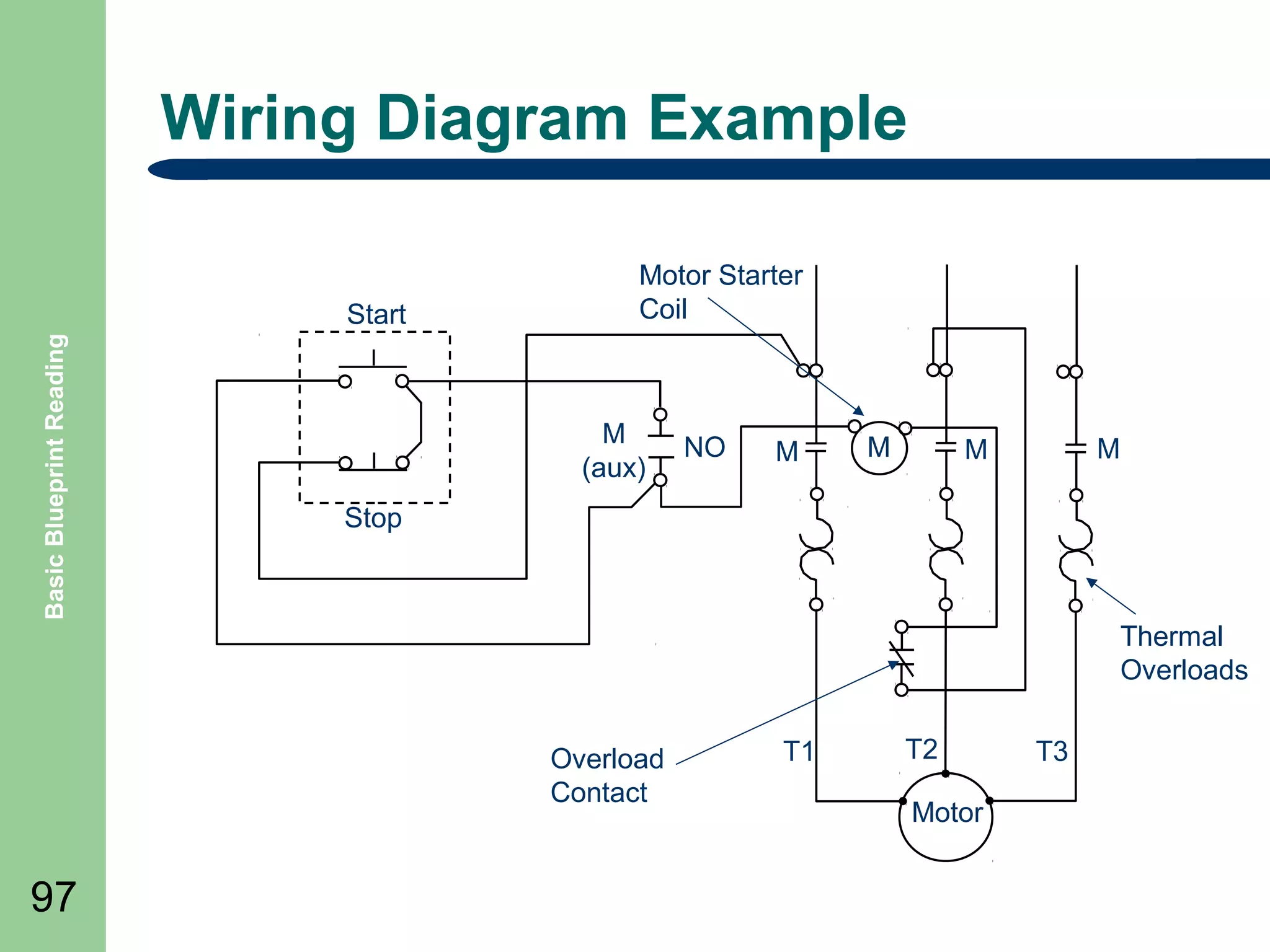
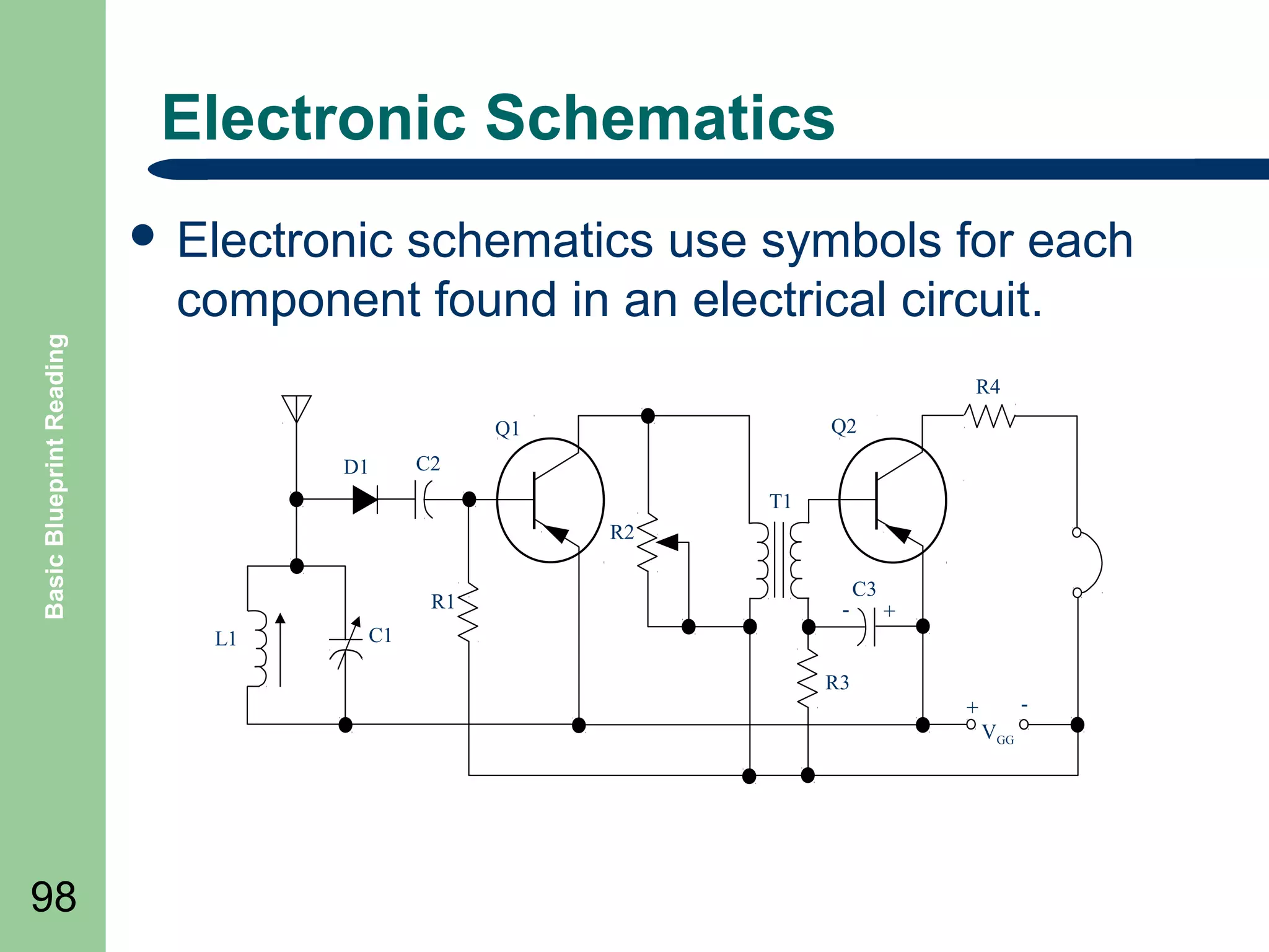
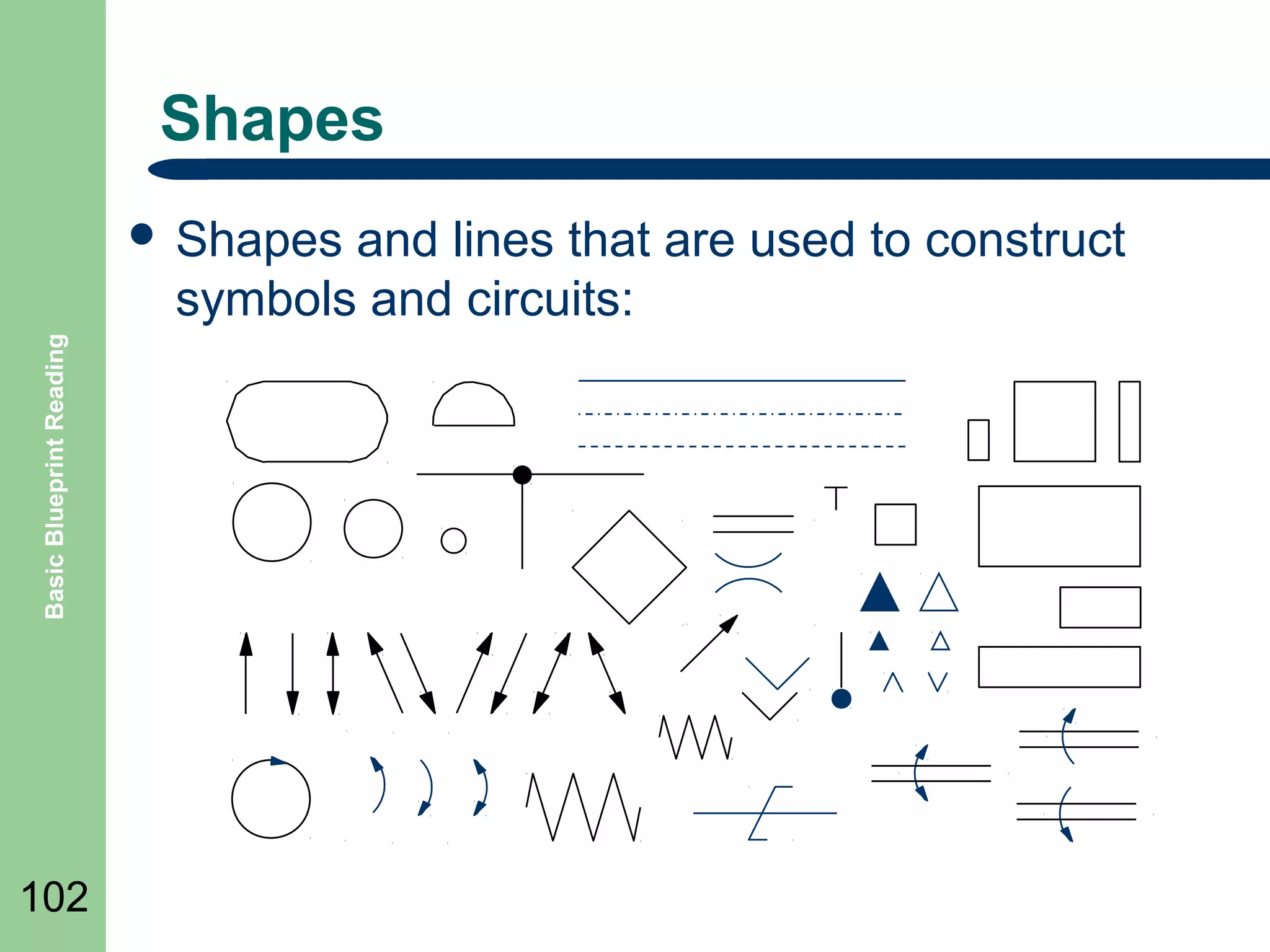
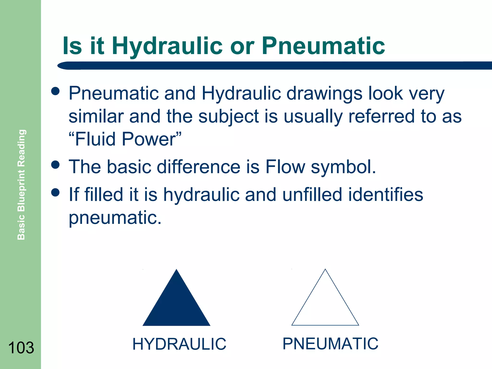
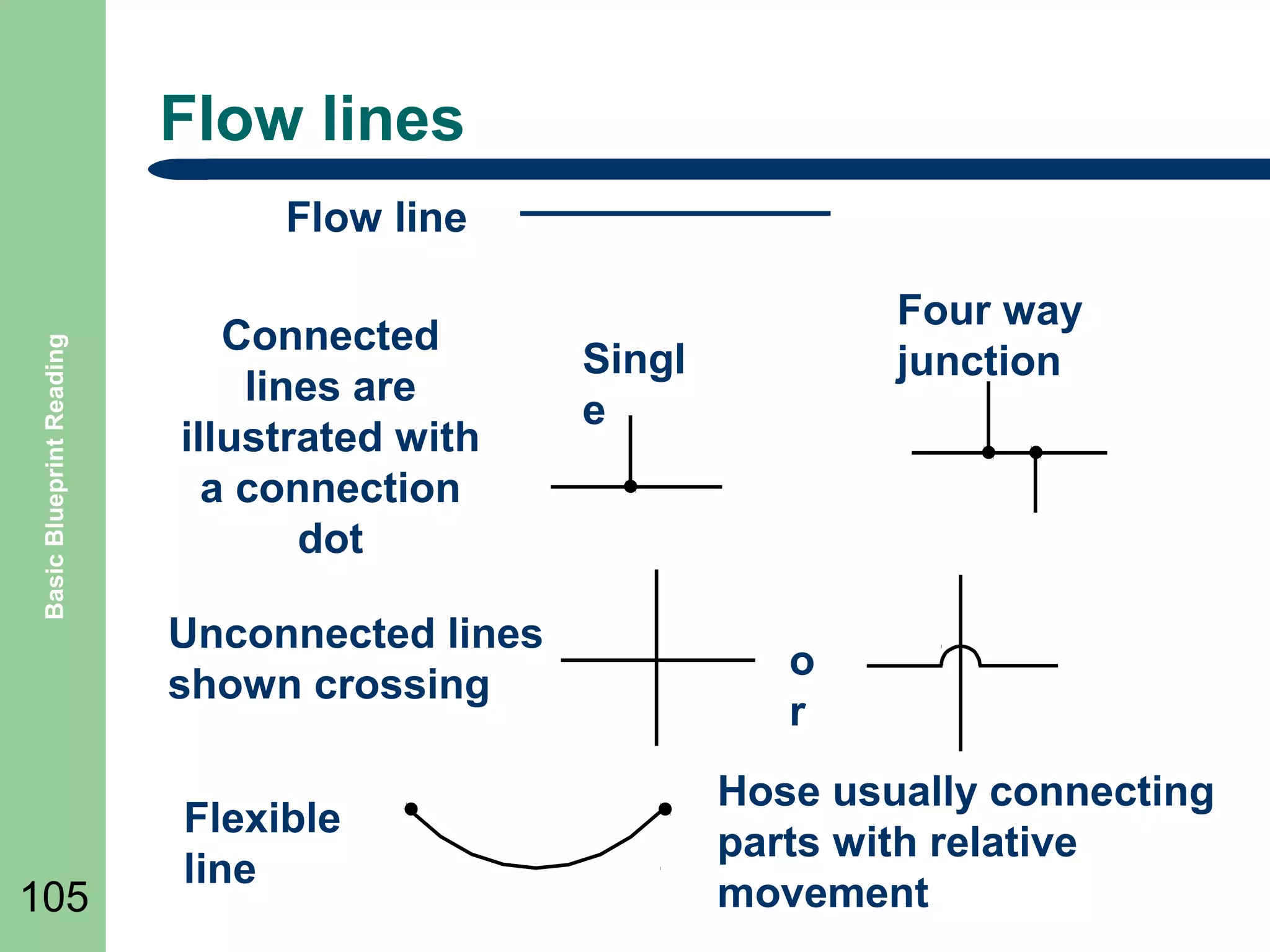
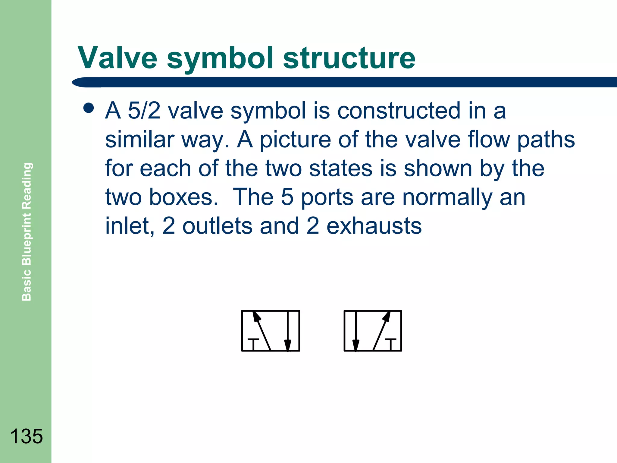
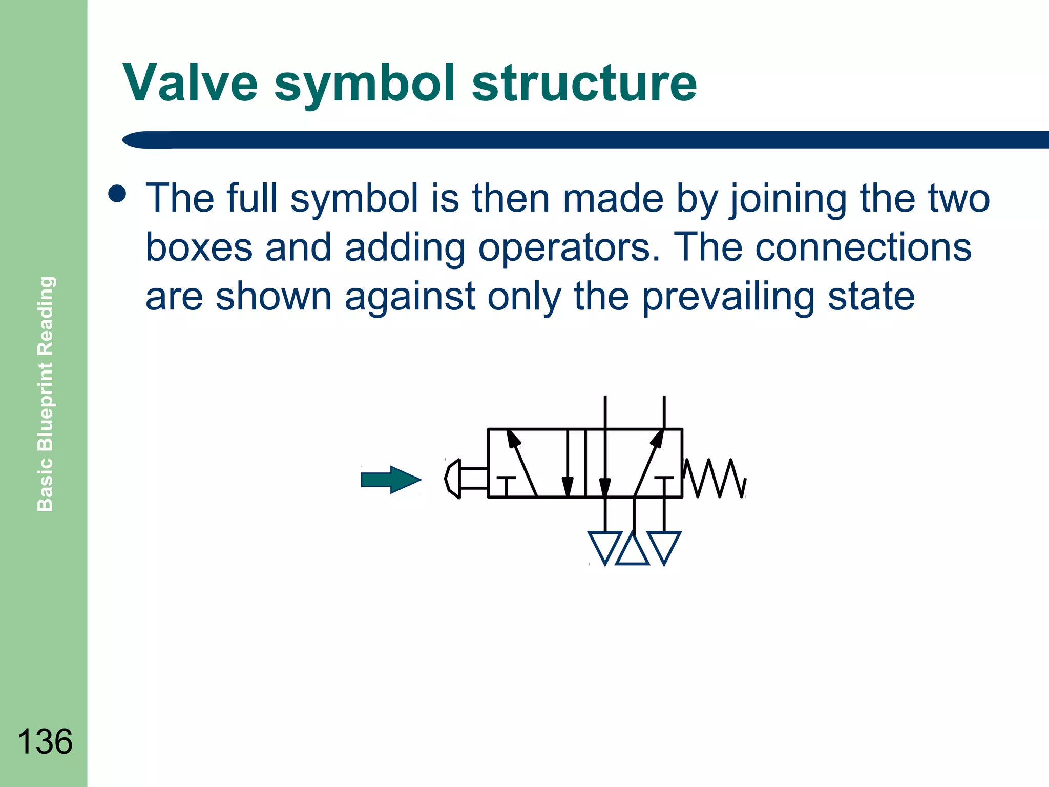
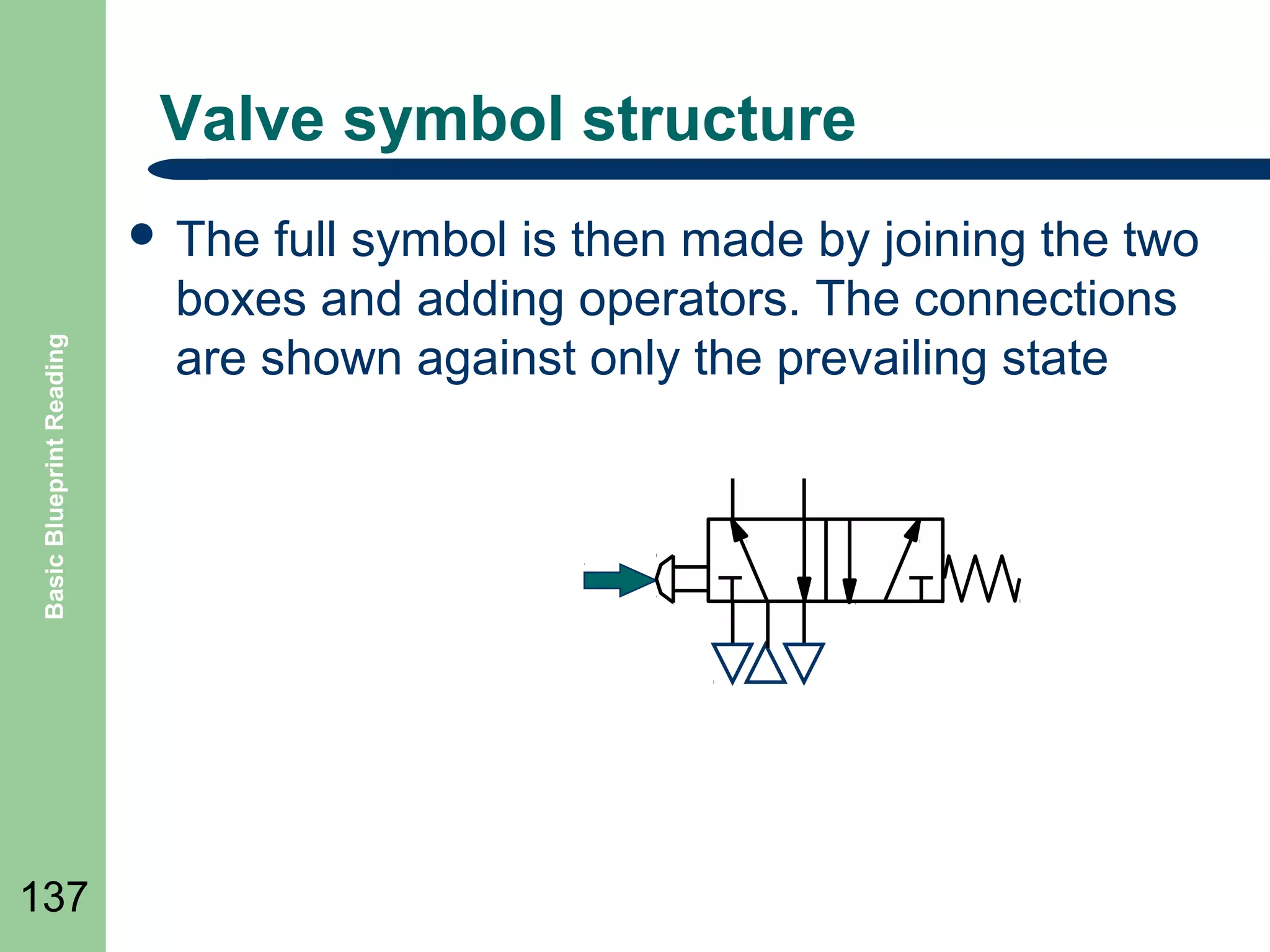
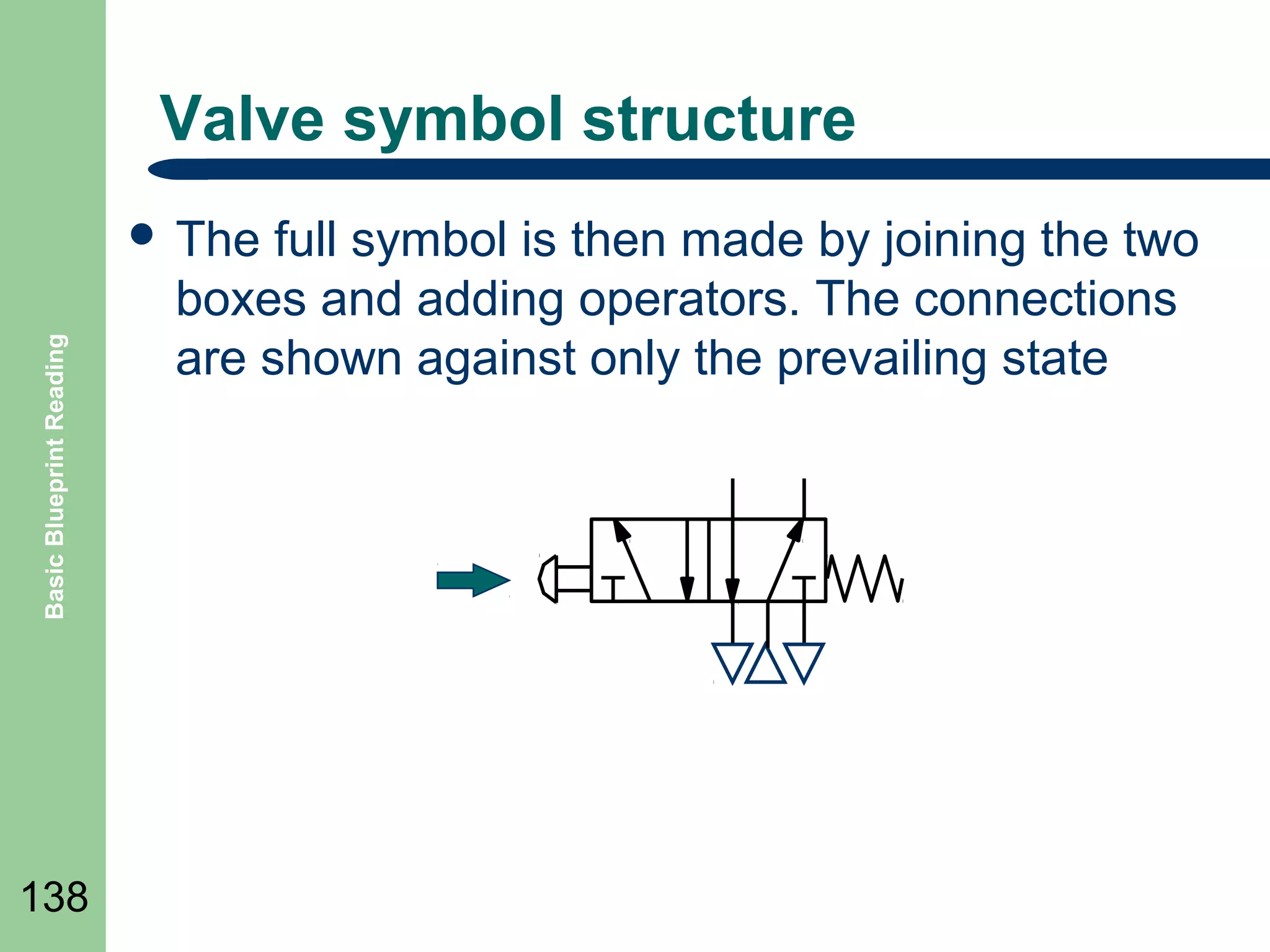
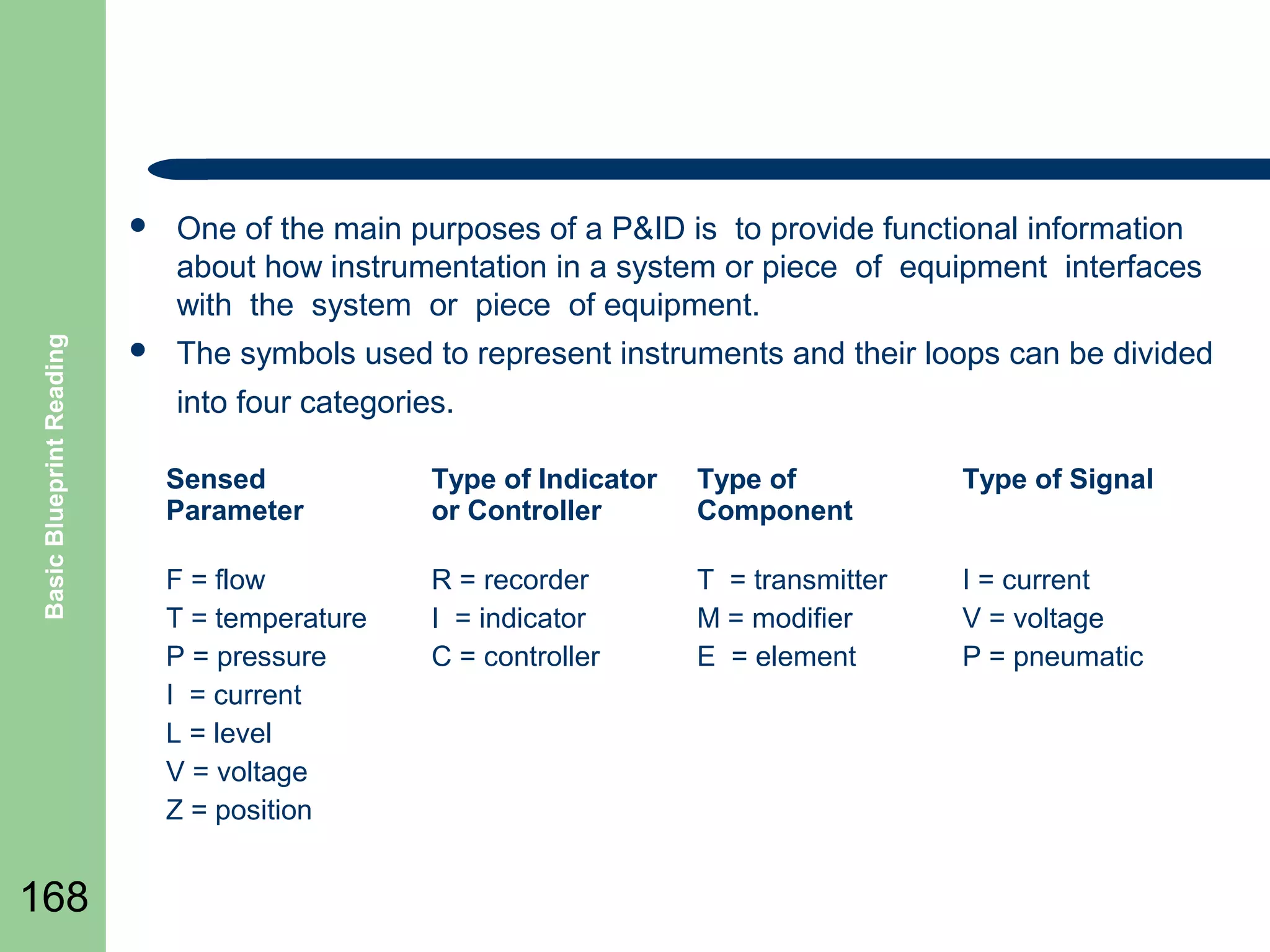
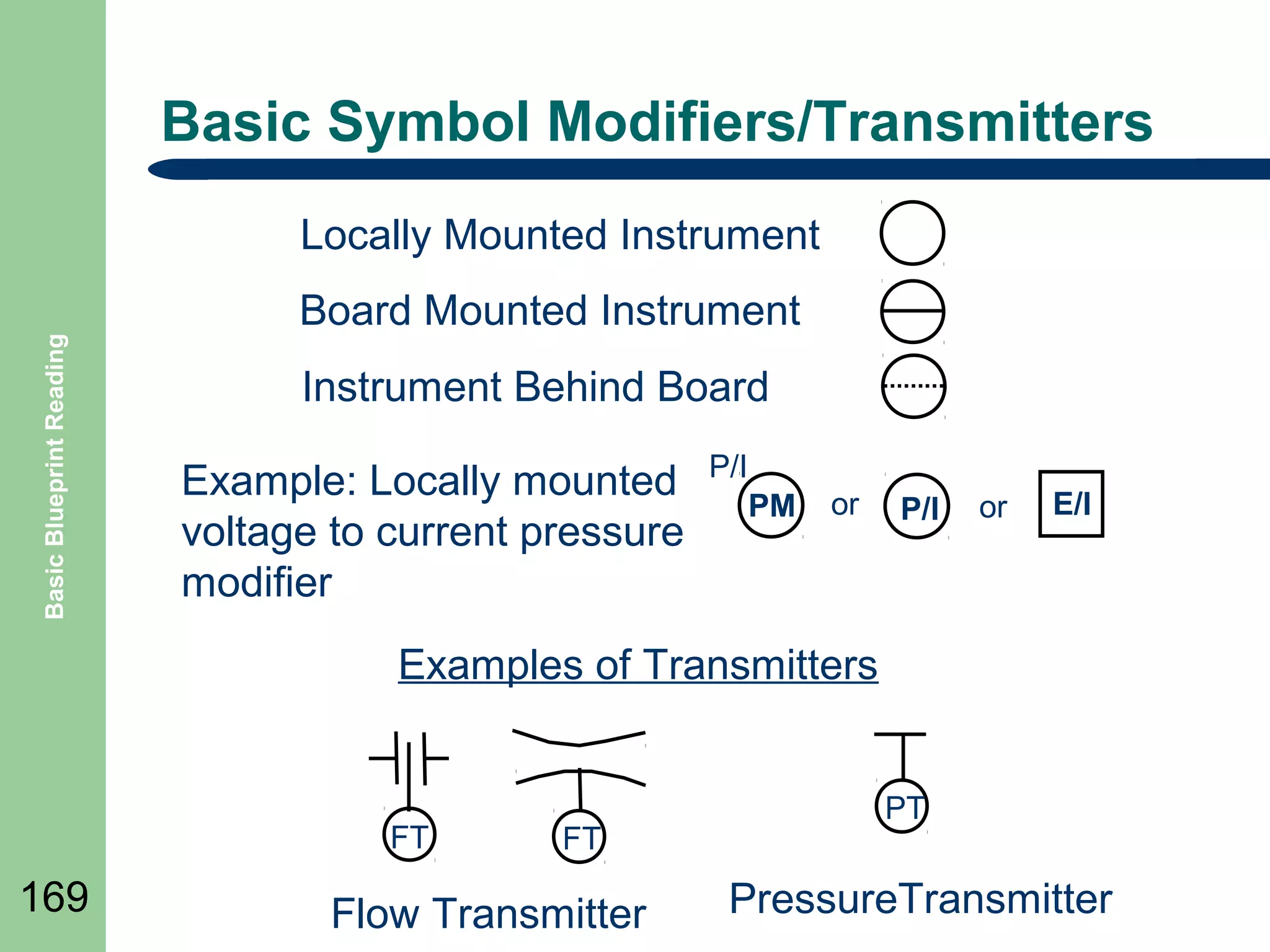
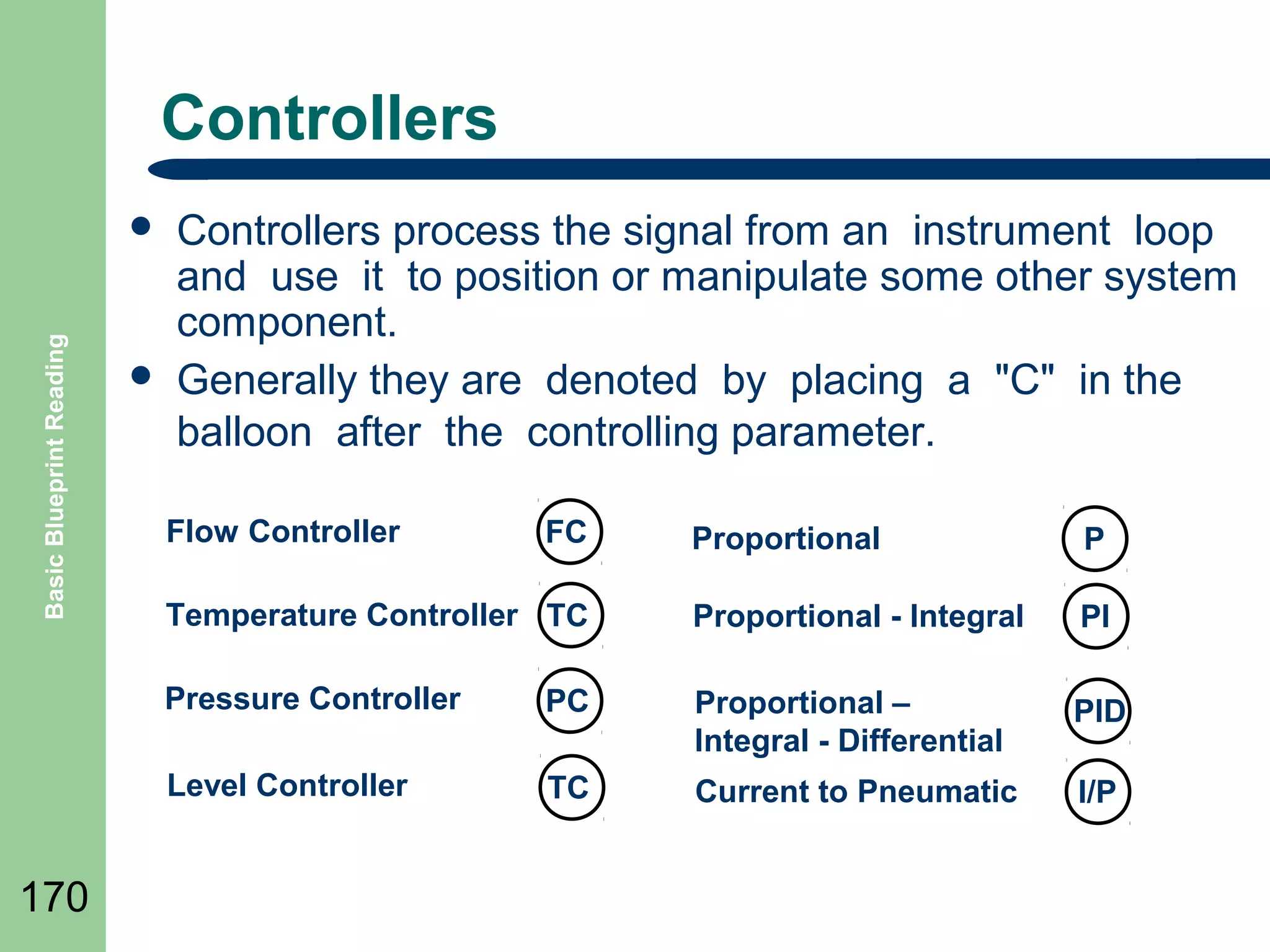
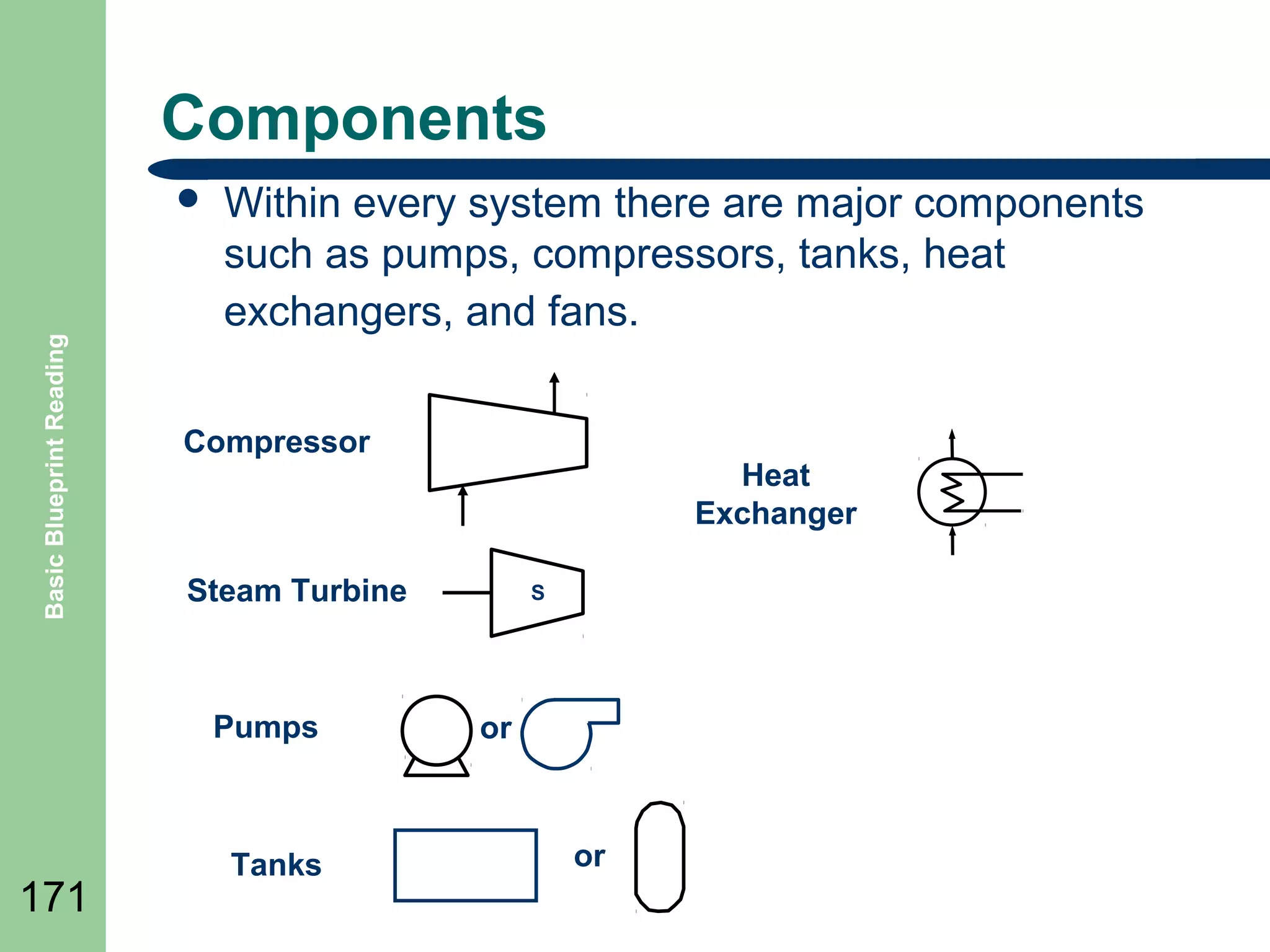
BASIC BLUEPRINT READING

1
SUBJECTS

Basic Blueprint Reading

๏ฌ DRAWING

2

BASICS
๏ฌ ELECTRICAL DRAWINGS
๏ฌ PNEUMATIC/HYDRAULIC DRAWINGS
๏ฌ PIPING AND PI&D DRAWINGS
๏ฌ CIVIL AND ARCHITECTURAL DRAWINGS
๏ฌ MACHINE DRAWINGS
DRAWING BASICS

3
Objectives

Basic Blueprint Reading

๏ฌ Define

4

basic industrial drawing structure
๏ฌ Define line types
๏ฌ Define types of drawings
Purpose of Drawings

Basic Blueprint Reading

๏ฌ Drawings

5

are used to convey information about a
wide range items such as:
๏ฌ Architectural building layouts
๏ฌ Electrical wiring
๏ฌ Pneumatic or Hydraulic layouts
๏ฌ Location of equipment
๏ฌ How to assemble equipment
๏ฌ Details of equipment
Types of Drawings

Basic Blueprint Reading

๏ฌ Civil
๏ฌ Architectural
๏ฌ Structural
๏ฌ Mechanical
๏ฌ Plumbing
๏ฌ Piping
๏ฌ Pneumatic/Hydraulic
๏ฌ Electrical

6
Engineering Drawings
general engineering drawing can be divided
into the following five major areas or parts.

Basic Blueprint Reading

๏ฌA

7

โ€“
โ€“
โ€“
โ€“
โ€“

1.
2.
3.
4.
5.

Title block
Grid system
Revision block
Notes and legends
Engineering drawing (graphic portion)
Drawing Sizes

Basic Blueprint Reading

๏ฌ

Drawings come in a alphabetical list of sizes for A to F
with D size being the most typical

A โ€“ (letter)

Metric
A4 (210 x 297)
A3 (297 x 420)

8 ยฝ by 11inches
B - 11 by 17inches

A2 (420 x 594)

C - 17 by 22 inches

A1 (594 x 841)

D - 22 by 34 inches
E - 34 by 44 inches
F - 28 by 40 inches

8

sizes

A0 (841 x 1189)
Title Blocks
blocks are the beginning point of a drawing
information.

Basic Blueprint Reading

๏ฌ Title

9

๏˜๏˜๏˜๏€  COMPANY
Revision Blocks
revision block notes any changes made
to a drawing

Basic Blueprint Reading

๏ฌ The

๏ฌ

10

Throughout a drawing the revision listed in the
revision block may be indicated by a symbol near the
modified portion of the drawing such as:
A
Parts Lists

Basic Blueprint Reading

๏ฌ Parts

11

Lists are called Bill of Materials. It is a list
of the material that is used to build the item that
is
Scales

Basic Blueprint Reading

๏ฌ Drawing

12

scale is a relationship of the size or
distance of the item on a drawing to the real
item.
๏ฌ For example a scale of ยผโ€ = 1โ€™ means a
measurement of ยผ inch (the quote symbol โ€œ is a
shorthand for inches) on the drawing equals 1
foot ( the apostrophe symbol โ€˜ is shorthand for
feet) of the real world item.
Grid System
drawing grid system allows a specific point
on a drawing to be referenced or found.

Basic Blueprint Reading

๏ฌA

1

2

3

4

5

6

A
B
C

13

This point on the drawing is B-3
Basic Lines

Basic Blueprint Reading

๏ฌ Object

lines
๏ฌ Hidden lines
๏ฌ Cutting plane lines
๏ฌ Centerlines
๏ฌ Extension lines
๏ฌ Dimension lines
๏ฌ Leaders line
๏ฌ Phantom lines
Basic Blueprint Reading

Object Line
The object line is a heavy, dark line which identifies
the visible edges of the drawn object or the surface
of an object.
Hidden Line

Basic Blueprint Reading

๏ฌ

The hidden line is used to show features or edges
of an object that is not visible. It is a broken line of
medium thickness.
Center Line

Basic Blueprint Reading

๏ฌ The

center line is used to locate the center of
features. It is usually a fine, broken line made of
alternating short and long dashes.
Dimension Line / Extension Line

Basic Blueprint Reading

๏ฌ Dimension

Lines are used to show the extent of
a dimension.
๏ฌ Extension Lines are use to extend a point from
an object.

Extension Line

Dimension Line
Phantom

Basic Blueprint Reading

๏ฌ Phantom

lines are used to represents the outline
of an adjacent part.
๏ฌ The also are used to show an alternate position
of a given part

Phantom
19
Leader

Basic Blueprint Reading

๏ฌ

A leader is a fine line used to define a point or area. It
may have a note, dimension value or a number at the
end of it

Grind Surface

1
Cutting Plane Line

Basic Blueprint Reading

๏ฌ

Cutting plane lines are used to indicate where an imaginary cut is
made through the object. If it is labeled the section may be redrawn
in detail in another part of the drawing.

A

A
Break Lines
lines are uses to terminate a view to
๏ฌ Short Break Line
conserve drawing space and avoid congestion.

Basic Blueprint Reading

๏ฌ Break

๏ฌ Break

lines are also used to separate internal
and external features with broken-out sections
Basic Blueprint Reading

Break Lines Example
The break line is being used to show a part
reduced in length on the drawing to conserve
space.

3โ€

250 feet
Section Lines

Basic Blueprint Reading

๏ฌ Section

lines are used where a surface is
illustrated as cut.
๏ฌ It normally is used in a sectional view.
๏ฌ The lines are normally drawn diagonally.
Dimensioning Systems
๏ฌ Different

systems of dimensioning are generally

Basic Blueprint Reading

used

25

โ€“
โ€“
โ€“

Fractional inch
Decimal inch
SI Metric
Fractional Inch Dimensioning

Basic Blueprint Reading

2 Dia
21/32 Dia
3/16

1/2
1 9/16 Dia

26
Decimal Inch Dimensioning

Basic Blueprint Reading

2.00 ร˜
.656 ร˜
.19

.50
1.56 ร˜

27
Metric Dimensioning

Basic Blueprint Reading

ร˜ 50
ร˜ 16.5
5

13
ร˜ 40

28
Dimensioning Example

Basic Blueprint Reading

Diameter symbol

Typical

Radius

29
Abbreviations

Basic Blueprint Reading

๏ฌ

Abbreviations are used to help reduce clutter and
simplify drawings. A table is included in the drawing.
BOTTOM

MH

MANHOLE

R

RADIUS

C/C

CENTER TO CENTER

MIN

MINIMUM

REF

REFERENCE

CMP

CORRUGATED METAL PIPE

N

NORTH

R/W

RIGHT OF WAY

CONC

CONCRETE

NC

NOT IN CONTACT

SCH

SCHEDULE

DIA

DIAMETER

NTS

NOT TO SCALE

SF

SQUARE FEET

E

EAST, ELECTRICAL

OC

ON CENTER

SQ

SQUARE

EL

ELEVATION

O.D.

OUSIDE DIAMETER

STA

STATION

FG

FINISH GRADE

OHW

OVERHEAD WIRES

T

TELEPHONE

H

HORIZONTAL

PL

PROPERTY LINE

TYP

TYPICAL

HP

HIGH POINT

POB

POINT OF BEGINNING

UNO

UNLESS NOTED
OTHERWISE

IE

30

BOT

INVERT ELEVATION

POE

POINT OF ENDING

INV

INVERT

PP

POWER POLE
Drawing Legends

Basic Blueprint Reading

๏ฌ Legends

31

are
boxes drawn on
the drawing to
illustrate some of
the common or
uncommon
symbols used.
Isometric Drawings
drawings are designed to show a three
dimensional view of an object.

Basic Blueprint Reading

๏ฌ Isometric

32
Perspective
is a method of drawing things as the
eye sees them.

Basic Blueprint Reading

๏ฌ Perspective

Vanishing point
33
Orthographic Drawings
projection shows the drawn object
from different views

Basic Blueprint Reading

๏ฌ Orthographic

Top
view

Left side

Right side
Front

Bottom

34

Projection view

Rear
Single Line Drawings

Basic Blueprint Reading

๏ฌ

35

๏ฌ
๏ฌ

๏ฌ

The single line format represents all electrical lines,
plumbing, air lines, hydraulic lines and piping, regardless
of size, as single line.
System equipment is connected to the lines are
represented by simple standard symbols.
By simplifying connections and equipment as single
lines allow the system's equipment and
instrumentation relationships to be clearly understood by
the reader.
These types of drawings are also called Schematics.
Civil

Basic Blueprint Reading

๏ฌ Civil

36

drawings are used to represent construction
on the earth or ground areas.
๏ฌ Civil drawings are sometimes called:
โ€“
โ€“
โ€“

site plans
plot plans
survey plans.

๏ฌ They

will show contours of the earth, building
locations, construction features, utilities, etc.
Contour Lines

Basic Blueprint Reading

๏ฌ

Contour lines are used in drawings called
topographic maps and are used to identify physical
features which uses contour lines to join points of
equal elevation (height) and thus show valleys and
hills, and the steepness of slopes. The elevation or
height is a number drawn along the line.
180
160
140
120

110

37
Architectural

Basic Blueprint Reading

๏ฌ Architectural

drawings or plans are used to
illustrate the design of a project.
๏ฌ They include items such as:
โ€“
โ€“
โ€“
โ€“
โ€“
โ€“

38

Working drawings
Structural drawings
Floor plans
Elevation drawings
Section drawings
Flow diagrams
Gridlines

Basic Blueprint Reading

๏ฌ Gridlines

refers to the letters and numbers, such
as A-1, which identifies the columns of a building
in a drawing.
C

B

A
1

Column A-1
2

Column symbol

39

3
Mechanical

Basic Blueprint Reading

๏ฌ Mechanical

40

drawings are the plans for objects
such as motors, assemblies for equipment, etc.
๏ฌ There are many types of drawings associated
with mechanical drawings such as:
โ€“
โ€“
โ€“

Exploded view
Detail
Assembly
Basic Blueprint Reading

Example Mechanical Detail

41
Basic Blueprint Reading

Example Assembly Drawing

42
Basic Blueprint Reading

An Exploded View

43
Pneumatic/Hydraulic

Basic Blueprint Reading

๏ฌ Pneumatic

44

or Hydraulic drawings are single line
drawings use symbols and lines to illustrate the
connection and equipment to be used in the
pneumatic or hydraulic equipment.

Single Line Schematic example
Plumbing/Piping
types of drawings are similar to
pneumatic/hydraulic schematics.

Basic Blueprint Reading

๏ฌ These

36.00

40.00

TEE
PIPELINE

Valve

TANK

Single Line Plumbing Example
45
Single Line Drawing
Single line plumbing drawing example

Basic Blueprint Reading

๏ฌA

36.00

40.00

TEE
PIPELINE

Valve

TANK

46
Basic Blueprint Reading

Orthographic Piping Drawing

47
P&ID

Basic Blueprint Reading

๏ฌ Piping

48

and Instrumentation Drawings
๏ฌ These drawings are similar to plumbing but are
intended to illustrate the complete piping system
and the controlled process flow of material.
๏ฌ All the equipment, pipelines, valves, pumps,
instruments and the controls to operate the
process are illustrated. They are not drawn to
scale.
Example P&ID

Basic Blueprint Reading

FROM FUTURE MAIN
VAPOR RECOVERY UNIT

SLUG
CATCHER

CS
CONTACTOR
H.P. BULK
SEPARATOR
COALESCING
FILTER NO. 1

FILTER
SEPARATOR

PRODUCTION FROM
SATELLITES (TYP.)

TEST
SEPARATOR

FILL FROM CIS
TRANSPORTER

HYDROCYCLONES
(TYP. 2)
FRESH CIS PUMPS
(TYP. 2)

49

FRESH CIS
CHARGE PUMPS
(TYP. 2)

FRESH CIS TANK
Electrical

Basic Blueprint Reading

๏ฌ Electrical

50

drawings are also single line drawings
or schematics that uses symbols for various
electrical equipment.
๏ฌ They are usually drawn in a style called a ladder
diagram.
๏ฌ Another form of drawing is a wiring diagram
which illustrates the wiring in a orthographic or
pictorial style.
Example Ladder

Basic Blueprint Reading

๏ฌ Ladder

schematics or diagrams are drawn with
the circuit between two vertical lines, usually the
power that supplies the circuit, thus each line
creates a โ€œrungโ€ to the ladder.
L1

115 VAC
Pushbutton

Pilot Light
L

51

L2
Example Wiring Diagram
wiring diagrams draws the single lines
from each device exactly as it would be wired.

Basic Blueprint Reading

๏ฌ Electrical

52
Electrical Schematics
schematics use symbols for each
component found in an electrical circuit.

Basic Blueprint Reading

๏ฌ Electronic

R4
Q2

Q1
D1

C2
T1
R2
R1

L1

-

C3

+

C1
R3

-

+
VGG

53
Summary

Basic Blueprint Reading

๏ฌ Review

Objectives
๏ฌ Question and Answer Session

๏ฌ RETURN

54

TO MAIN MENU
ELECTRICAL DRAWINGS

55
Objectives

Basic Blueprint Reading

๏ฌ Define

56

how industrial electrical drawings are
structured.
๏ฌ Define Graphical Symbols
๏ฌ Define Electrical wiring diagrams
Types of Electrical Drawings

Basic Blueprint Reading

๏ฌ Wiring

57

Diagrams ๏ฌ Block Diagrams ๏ฌ Sequence Charts โ€“
๏ฌ Electronic Schematics -
Diagrams

Basic Blueprint Reading

๏ฌ Electrical

58

diagrams are commonly multi-sheet
drawings of the wiring of the electrical devices
associated with a main control panel, its field
devices and sub-panels.
๏ฌ It is usually drawn as a ladder diagram.
Electrical Diagrams
๏ฌ

Basic Blueprint Reading

๏ฌ

59

๏ฌ
๏ฌ

๏ฌ

The Diagram is drawn between vertical lines or
ladder.
All devices are shown between the lines and may
be referenced as โ€œSingle Lineโ€ diagrams
Controlled, such as relays, devices are drawn on
the right side.
Contacts, switches and other controlling devices
are shown between controlled device and left
vertical line
Overloads and other circuit breaking devices may
be connected to the right of the controlled device.
Example Diagram
DISC
1M

1FU

1OL

1L1

1T1

L1
2FU

1T2

1L2

L2

460V
3ร˜
60

HYDRAULIC PUMP MOTOR
3 HP 1800 RPM
FRAME 213

1MTR
3FU

1T3

1L3

L3

Basic Blueprint Reading

15 AMP

2OL

2T1

2MTR
2T3
H3

H1

H2
H4

T

X1
10 AMP
6FU

H2
10 AMP
5FU

2PB
START MOTORS

1PB
MASTER STOP
1

115 V

10 AMP
4FU

R
2OL

1OL

3

8
7

1

1

9

2

10

1M

CRM

AUTOMATIC

CRM

4PB

11

CRH

MASTER RELAY 3,3

12

AUTOMATIC
5, 14, 16, 21
โ€œAUTOMATICโ€

CRA
5

5PB
MANUAL

14

6

โ€œMANUALโ€

A

CYCLE START
5

16

8
15

MANUAL
6, 7, 15, 18, 23

CRH
3LT

CRH

7

6PB

CRA

R

2LT
3PB
RESET
11

10

6

13

5

5

9

4

1M

CRM

3

4

10 AMP
7FU

1LT

2

60

SPINDLE MOTOR
2 HP 1800 RPM
FRAME 184

2T2

1LS

2CR

18

17

2LS
19

5LS

6LS
20

7CR
21

6CR
22

5
6

23
1 CR

7PB
1CR

26

26

22

21

21

CLAMP PART CONTROL
9, 33, 33, 35, 35
Lines

Basic Blueprint Reading

๏ฌ Wiring

61

๏ฌ Field

Wiring (external to panel)
Connections

Basic Blueprint Reading

Wiring Not Connected

Wiring Connected

Termination
or connection

Terminal strip
and terminal
designation

62

TS4-15
Graphical Symbols

Basic Blueprint Reading

๏ฌ

63

๏ฌ

๏ฌ

Graphical symbols are used on electrical diagrams to
illustrate the wiring between electrical devices and
terminals. The electrical devices are either shown in
block diagram form or using commonly defined symbols.
The following symbols are but a few of those that can be
used.
A chart should be included on drawings to illustrate any
added by the manufacturer.
Graphical Symbols Contโ€™d

Basic Blueprint Reading

DISCONNECT
Symbol - DISC

64

CIRCUIT
BREAKER - CB
Or for a
single
CB
Graphical Symbols Contโ€™d
Resistor

Tapped Resistor

Basic Blueprint Reading

or
Rheostat

Potentiometer

Fuses
65
Relay and Solenoid Symbols

Basic Blueprint Reading

RELAYS, TIMERS, ETC.
Normally
Open
Contact
Normally
Closed
Contact
Coil
66

SOLENOIDS, BRAKES,
ETC.
Motors Symbols

Basic Blueprint Reading

3 PHASE MOTOR

DC MOTOR

A

DC MOTOR FIELD
67

or

A
Basic Blueprint Reading

Transformer Symbols

68

H1

H3

H2

H4

Primary
or Input
Secondary
or Output

X1

X2
Pilot Lights

Basic Blueprint Reading

PUSH-TO-TEST

69

R

R
Limit Switch Symbols
NORMALLY
CLOSED

HELD
OPEN

70

NORMALLY
OPEN

HELD
CLOSED

HELD
OPEN

NORMALLY
OPEN

Basic Blueprint Reading

NORMALLY
CLOSED

HELD
CLOSED
Proximity Switch Symbols

Basic Blueprint Reading

PROXIMITY SWITCH

71

Normally
Closed

Normally
Open
Liquid Level Switches

Basic Blueprint Reading

NORMALLY
OPEN

72

NORMALLY
CLOSED
Thermal Switch

Basic Blueprint Reading

NORMALLY OPEN

73

NORMALLY
CLOSED
Pressure Switch

Basic Blueprint Reading

NORMALLY
OPEN

74

NORMALLY
CLOSED
Basic Blueprint Reading

Foot Switches

75

NORMALLY
CLOSED

NORMALLY
OPEN
Basic Blueprint Reading

Toggle Switch

76
Flow Switches

Basic Blueprint Reading

NORMALLY OPEN

77

NORMALLY
CLOSED
Selector Switch
3-POSITION

Basic Blueprint Reading

Second
Off
First
Position Position Position

78

Circuit is
connected when
switch is in this
position.

2-POSITION
Pushbuttons

Basic Blueprint Reading

SINGLE CIRCUIT

79

NORMALLY
OPEN
NORMALLY
CLOSED

DOUBLE
CIRCUIT
Basic Blueprint Reading

E-Stop Pushbuttons

80
Time Delay Relay

Basic Blueprint Reading

NORMALLY
OPEN
ENERGIZED

DE-ENERGIZED

81

NORMALLY
CLOSED
One-line diagram example

Basic Blueprint Reading

๏ฌ

A one-line diagram
uses single lines
and graphic
symbols to indicate
the path and
components of an
electrical circuit.

Switch symbol
Fuse
symbol
Single line
conductors
PLC

Pushbutton
symbol

Controller
symbol
Motor
symbol

82

M
Control Device Labeling

Basic Blueprint Reading

๏ฌ

๏ฌ

Control devices, that are represented in the wiring diagrams, are
photocells, limit switches, local lights, solenoids, air pressure
switches, etc. are identified by wiring diagram line number or I/O
address if a PLC is controlling it.
When a line number is used, such as 211LS, the 2 indicates that the
device is on page two line 11 of the Wiring Diagram (WD) drawing.

111PB

111CR

210
211LS
211

83

211Sol
Wiring and Wire Identification
๏ฌ

Wiring color code

Basic Blueprint Reading

๏ฌ BLACK

- Line, Load and Control Circuits at Line Voltage
๏ฌ RED โ€“ AC Control Circuits
๏ฌ BLUE โ€“ DC Control Circuits
๏ฌ YELLOW โ€“ Interlock Control Circuits
๏ฌ GREEN โ€“ Equipment grounding
๏ฌ WHITE โ€“ Grounded Circuit Conductor
๏ฌ

Wire Identification
โ€“

84

Conductors are identified at each termination by marking with a
number to corresponding with the diagram on the wire
Device Designations

Basic Blueprint Reading

๏ฌ

85

The device designations or abbreviation, such as examples
below, are used on diagrams in connection with the
corresponding graphical symbols to indicate the function of the
particular device.
CB - Circuit Breaker
LS โ€“ Limit Switch
CR - Control Relay
T - Transformer
FU - Fuse
MTR - Motor
LT - Pilot Light
DISC โ€“ Disconnect
OL - Overload Relay
PB - Pushbutton
S - Switch
Line Numbers

Basic Blueprint Reading

๏ฌ Each

line in a electrical drawing should be
numbered starting with the top line and
reading down.
115 VAC

L1
Pushbutton

L2
Relay

1

CR1
Limit Switch

Pressure
Switch

Solenoid

2
Foot Switch
3
4

86

Relay
CR2

Temperature Switch

Line Numbers
Wire-Reference Numbers

Basic Blueprint Reading

Wire Numbers
115 VAC

L1
Pushbutton
1
2

3

1
1

1

CR3

2
CR1

4

87

3

Relay
CR1

4

( 2, 3 )

2

Limit Switch

5

Foot Switch
1

L2

7

CR1

CR2

6

8

Relay
CR2
Relay
CR3

4

(4)

4

(1)
Numerical Cross Reference
115 VAC

L1
Basic Blueprint Reading

Pushbutton
1

Relay
CR1

( 2, 3 )

CR1
2
Limit Switch

CR1

3

Relay
CR2

Foot Switch
4

88

CR3

L2

CR2

(4)

Relay
CR3

Cross Reference to
Line Numbers

(1)
Terminal Numbers
115 VAC

Basic Blueprint Reading

L1
Pushbutton
1
2

3

1

2
CR1

1
1

1

CR3

89

3

CR1

4

( 2, 3 )

10

2

3

Limit Switch

CR1

5

Foot Switch
4

Relay
2

5

1

L2

6

CR2

7
1

3

Relay

6
2

CR2

2

CR3

(4)

4

(1)

10

Relay

8

4

10
Panel/Door Layouts
Layout.

1โ€ X 3โ€

1T1

9
TE
RM
.

1T2
1T3
271

46
0V

272
2T3

DISC

2OL

1M

9โ€

1T
B

๏ฌ Panel

1
1/2
โ€X
3โ€

Layout

1

1 1/2โ€ X 3โ€

2
3
4

4F
U
5F
U

5

36
TE
RM
.
R

1LT

START
MOTORS

2LT

R

AUTOMATIC

4PB

2PB

A

3LT

R

6F
U
7F
U

EMERG.
RETURN
ACTIVE

MANUAL

4LT

EMERG.
RESET

MANUAL

MASTER
STOP

RESET
3PB

11PB

6CR

10PB

5LT

G

HEAD
FORWARD

R

8CR

9CR

6 1/2โ€
7 1/8โ€

29
TE
RM
.
9LT

1 1/2โ€ X 3โ€

HEAD
RETURN

8PB

6LT

7CR

9PB

11
5V

CYCLE
UNCLAMP

A

5CR

55

26 1/2โ€

1
1/2
โ€X
3โ€

7LT

4CR

53

LUBE
FAULT

7 1/2โ€

1 1/2โ€ X 3โ€

3T
B

A

FULL
DEPTH

3CR

47
52

CLAMPS
ARE IN

90

2CR

1 1/2โ€ X 3โ€

51

HEAD RETRACTED

CRH

115V

EMERG.
RETURN

1PB

CRA

1 1/2โ€ X 3โ€

1CR

12PB

5PB

CRM

11
5V

AUTOMATIC

T

1
1/2
โ€X
3โ€

MOTORS
RUNNING

460V

1FT8

8 TERM

60 62 64 66 68 70

15 1/8โ€

8F
U
9F
U
10F
U
11F
U
12F
U
13F
U

๏ฌ Door

1FU 2FU 3FU

2T
B

Basic Blueprint Reading

9 1/2โ€
1OL

60 62 64 66 60 70

5 1/2โ€

115 Vโ€
Drawing Identification
Description

Air Diagram (Mechanical)

These are detailed air Schematic drawings. They show the assembly, material list, and air
piping diagram for the air operated devices.

E

Scale Layout
(Mechanical)

These are drawings of a conveyor or part of a conveyor. Used for construction. Individual
sheets are numbered starting from No.1.

EL

Electrical Layout
(Electrical)

These drawings dimensionally locate all electrical equipment on a layout drawing. They are
directly referenced to the WD or control panel by the suffix to the EL number.

EM

Electro Mechanical
(Electrical)

These drawings are for electro mechanical devices used on a job. Example; a code card of
limit switch operator, etc. They are numbered consecutively for the job.

EO

General Layout
(Mechanical)

These drawings are dimensionally to scale, but used for general purposes, e.g., complete
plant layout to small scale, including many conveyors. Individual sheets are numbered
starting from No. 1.

HO

Hydraulic Diagram
(Mechanical)

This is a drawing of a hydraulic control circuit.

PL

Pneumatic Layout
(Mechanical)

These drawings show the placement of pneumatic devices in relation to the conveyor path.
This type of drawing will also reference which of the air diagram drawings (AD) are
associated to a pneumatic device.

WD

91

Type of Drawing

AD

Basic Blueprint Reading

Prefix

Wiring Diagram
(Electrical)

This complete engineering of an area control includes: schematics, panel layout, and
pushbutton stations.

WDO

General Information
(Electrical)

This drawing is used to convey general information relative to the system control.
Block Diagrams

Basic Blueprint Reading

๏ฌ Block

92

diagrams are simple block diagrams which
provides a means to illustrate a control system in
a simple graphic format.
๏ฌ Block diagrams are also used to provide
functional information.
๏ฌ Block diagrams are also used to illustrate the
interconnection of different machines
Basic Blueprint Reading

Example Block Diagram
Start
pushbutton
on

Process 1 starts
if limit switch on

Process 1 stops
if limit switch off

93
Sequence Charts
SEQUENCE OF OPERATION

Basic Blueprint Reading

A.

94

B.

C.

PRESS โ€œSTART MOTORSโ€ PUSHBUTTON โ€œ2PBโ€ MOTORS START โ€œMOTORS RUNNINGโ€ LAMP โ€œ1LTโ€ ARE
ENGERGIZED.
PRESS EITHER AUTOMATIC โ€œ4PBโ€ OR MANUAL โ€œ5PBโ€ PUSHBUTTON, CORRESPONDING RELAY AND
LAMP ARE ENERGIZED.
NOTE: TO SWITCH FROM MANUAL TO AUTOMATIC. OPERATOR MUST PRESS โ€œRESETโ€ PUSHBUTTON
โ€œ3PBโ€ BEFORE PRESSING AUTOMATIC PUSHBUTTON โ€œ4PBโ€.
AUTOMATIC CYCLE WITH MOTORS RUNNING AND โ€œCRAโ€ ENERGIZED. MACHINE IS SET FOR
AUTOMATIC CYCLE HEAD MUST BE RETRACTED AND PART UNCLAMPED TO START CYCLE.
1.
OPERATOR LOADS PART IN FIXTURE AND PRESSES BOTH โ€œCYCLE STARTโ€ PUSHBUTTONS
โ€œ6PBโ€ AND โ€œ7PBโ€ ENERGIZING โ€œ1CRโ€ (SOL A AND SOL C) TO CLAMP PART
2.
CLAMPED PART TRIPS โ€œ1LSโ€ AND โ€œ2LSโ€. ENERGIZING โ€œ8CRโ€
RELAY โ€œ3CRโ€ (SOL E)
IS ENERGIZED MEMENTARILY STARTING HEAD FORWARD IN RAPID ADVANCE. HEAD CAMS
VALVE INTO FEED.
3.
WHEN HEAD IS IN FORWARD POSITION, โ€œ3LSโ€ IS TRIPPED, ENERGIZING RELAY โ€œ5CRโ€.
4.
โ€œ5CRโ€ CONTACT ENERGIZES RELAY โ€œ4CRโ€ (SOL F) AND HEAD RETURNS.
5.
WHEN HEAD IS FULY RETRACTED, โ€œ4LSโ€ IS TRIPPED, DE-ENERGIZING โ€œ4CRโ€ AND ENERGIZING
โ€œ7CRโ€ WHICH ENERGIZES โ€œ6CRโ€ (SOL B AND SOL D) UNCLAMPING PART.
6.
WHEN PART IS UNCLAMPED, โ€œ5LSโ€ AND โ€œ6LSโ€ ARE TRIPPED, DE-ENERGIZING RELAY โ€œ6CRโ€.
7.
โ€œ2CRโ€ RELAY PREVENTS MACHING RE-CYCLING IF BOTH โ€œCYCLE STARTโ€ PUSHBUTTONS ARE
NOT RELEASED.
Electrical Layouts - EL

Basic Blueprint Reading

๏ฌ Electrical

95

layouts are architectural drawings of
the building that shows and identifies the
electrical devices associated with a electrical
diagram.
Wiring Connection Diagrams

Basic Blueprint Reading

๏ฌ Wiring

96

(connection) diagram โ€“ a diagram that
shows the connection of an installation or its
component devices or parts.
๏ฌ This type of wiring diagram shows, as closely as
possible, the actual location of each component
in a circuit, including the control circuit and the
power circuit.
Wiring Diagram Example

Basic Blueprint Reading

Start

Motor Starter
Coil

M
(aux)

NO

M

M

M

M

Stop

Thermal
Overloads
Overload
Contact

97

T1

T2
Motor

T3
Electronic Schematics
schematics use symbols for each
component found in an electrical circuit.

Basic Blueprint Reading

๏ฌ Electronic

R4
Q2

Q1
D1

C2
T1
R2
R1

L1

-

C3

+

C1
R3

-

+
VGG

98
Summary

Basic Blueprint Reading

๏ฌ Review

Objectives
๏ฌ Question and Answer Session

๏ฌ RETURN

99

TO MAIN MENU
PNEUMATIC / HYDRAULIC DRAWINGS

100
Objectives

Basic Blueprint Reading

๏ฌ Define

101

Fluid Logic Symbols
๏ฌ Define Fluid Logic Diagrams Define
Shapes
and lines that are used to construct
symbols and circuits:

Basic Blueprint Reading

๏ฌ Shapes

102
Is it Hydraulic or Pneumatic

Basic Blueprint Reading

๏ฌ Pneumatic

103

and Hydraulic drawings look very
similar and the subject is usually referred to as
โ€œFluid Powerโ€
๏ฌ The basic difference is Flow symbol.
๏ฌ If filled it is hydraulic and unfilled identifies
pneumatic.

HYDRAULIC

PNEUMATIC
Fluid Power Drawings

Basic Blueprint Reading

๏ฌ This

104

type of drawing, like electrical drawings are
also considered single line drawings.
๏ฌ The line is either an air or hydraulic line
connected to a device
๏ฌ The devices are shown as symbols whose intent
is show the fluid flow and mechanical operation
of the device as well as type of device.
Flow lines

Basic Blueprint Reading

Flow line

105

Connected
lines are
illustrated with
a connection
dot
Unconnected lines
shown crossing
Flexible
line

Four way
junction

Singl
e

o
r
Hose usually connecting
parts with relative
movement
Basic Line Symbols

Basic Blueprint Reading

Line

Dashed

Chain

Line
106

Spring

Working line, pilot
supply, return, electrical
Pilot control, bleed,
filter
Enclosure of two
or more functions
in one unit
Electrical line

2
10

12
3

1
Circle Shapes

Basic Blueprint Reading

Circles
energy conversion units
measuring instrument

mechanical link
roller
107
Squares and Rectangles

Basic Blueprint Reading

Square

control component
connections perpendicular
to sides
conditioning apparatus
connections to corners

Rectangle

108

Square at
45o

cylinders and valves
Squares and Rectangles

Basic Blueprint Reading

Rectangles

109

piston

certain control
methods
Basic Symbols

Basic Blueprint Reading

Semi-circle

Capsule

Double line

110

rotary actuator, motor or
pump with limited angle
of rotation
pressurised reservoir
air receiver, auxiliary
gas bottle
mechanical
connection
piston rod, lever,
shaft
Functional Elements

Basic Blueprint Reading

Triangle

Spring

Arrow

111

Direction and nature of fluid,
open pneumatic or filled
hydraulic

Long sloping indicates
adjustability
Functional Elements

Basic Blueprint Reading

Arrows
Straight or sloping path and flow
direction, or motion through a
device
Tee

Restriction

112

Closed path or port
Basic Blueprint Reading

Functional Elements
Curved arrows are
used to illustrate
rotary motion
Shaft rotation

both
Seating or connection
used in check valves
and connectors

113

clockwise from right hand
end
Functional Elements

Basic Blueprint Reading

Temperature

Opposed
solenoid
windings

Operator

Prime mover

114

Indication or control
size to suit

M

Electric motor

M
Function components

Basic Blueprint Reading

Silencer

Pressure to electric switch
preset

Pressure to electric switch
adjustable
115
Basic Blueprint Reading

Function components
Uni-directional flow regulator

Rotating joint
Pressure indicator
Pressure drop indicator

116
Plant

Basic Blueprint Reading

Compressor and electric
motor
Air receiver
Isolating valve

Air inlet filter

117

M
Combination units

Basic Blueprint Reading

FRL with shut off valve and
pressure gauge

Lubro-control unit
Filter and lubricator
Filter regulator with gauge

118

FRL Combined unit
Basic Blueprint Reading

Filters
Filter with manual drain

Filter with automatic drain

Filter with automatic drain and
pressure drop indicator
119
Pressure regulators

Basic Blueprint Reading

๏ฌ

A pressure regulator symbol represents a normal state
with the spring holding the regulator valve open to
connect the supply to the outlet.

Adjustable Regulator
simplified

Adjustable Regulator with
pressure gauge simplified
120
Pressure relief valves

Basic Blueprint Reading

๏ฌ

A pressure relief valve symbol represents a normal
state with the spring holding the valve closed.

Adjustable relief valve simplified

Preset relief valve simplified
121
Pressure regulators

Basic Blueprint Reading

Pre-set relieving

Pre-set relieving with
pressure gauge
Adjustable relieving

Adjustable relieving with
pressure gauge
122
Valve symbol structure

Basic Blueprint Reading

๏ฌ The

123

function of a valve is given by a pair of
numerals separated by a stroke, e.g. 3/2..
๏ฌ The first numeral indicates the number of main
ports. These are inlets, outlets and exhausts but
excludes signal ports and external pilot feeds.
๏ฌ The second numeral indicates the number of
states the valve can achieve.
Valve symbol structure

Basic Blueprint Reading

๏ฌA

3/2 valve therefore has 3 ports (normally
these are inlet, outlet and exhaust) and 2
states (the normal state and the operated
state)
๏ฌ The boxes are two pictures of the same
valve

operated
124

normal
Basic Valve Symbols
๏ฌ

Basic Blueprint Reading

๏ฌ

125

๏ฌ

๏ฌ

๏ฌ
๏ฌ

Valve switching positions are illustrated with squares on a
schematic.
The number of squares is used to illustrate the quantity of
switching positions.
Lines within the boxes will indicate flow paths with arrows
showing the flow direction.
Shut off positions are illustrated by lines drawn at right
angles to the flow path.
Junctions within the valve are connected by a dot.
Inlet and outlet ports to the valve are shown by lines
drawn to the outside of the box that represents the normal
or initial position of the valve
Valve symbol structure

Basic Blueprint Reading

๏ฌA

126

valve symbol logic block will show the symbols
for each position of the valve states joined end to
end as illustrated in the next slide.

operated

normal
Valve symbol structure
valve logic state is illustrated with its state
block joined end to end

Basic Blueprint Reading

๏ฌ Each

127

operated

normal
Valve symbol structure
port connections are shown to only one of
the diagrams to indicate the prevailing state

Basic Blueprint Reading

๏ฌ The

128

normal
Valve symbol structure
operator for a particular state is illustrated
against that state

Basic Blueprint Reading

๏ฌ The

129

Operated state
produced by
pushing a button
Valve symbol structure
operator for a particular state is illustrated
against that state

Basic Blueprint Reading

๏ฌ The

130

Operated state
produced by
pushing a button

Normal state
produced by
a spring
Valve symbol structure
operator for a particular state is illustrated
against that state

Basic Blueprint Reading

๏ฌ The

131

Operated state
produced by
pushing a button

Normal state
produced by
a spring
Valve symbol structure

Basic Blueprint Reading

๏ฌ The

132

valve symbol can be visualised as moving to
align one state or another with the port
connections
Valve symbol structure

Basic Blueprint Reading

๏ฌ The

133

valve symbol can be visualised as moving to
align one state or another with the port
connections
Valve symbol structure

Basic Blueprint Reading

๏ฌ The

134

valve symbol can be visualised as moving to
align one state or another with the port
connections
Valve symbol structure

Basic Blueprint Reading

๏ฌA

135

5/2 valve symbol is constructed in a
similar way. A picture of the valve flow paths
for each of the two states is shown by the
two boxes. The 5 ports are normally an
inlet, 2 outlets and 2 exhausts
Valve symbol structure

Basic Blueprint Reading

๏ฌ The

136

full symbol is then made by joining the two
boxes and adding operators. The connections
are shown against only the prevailing state
Valve symbol structure

Basic Blueprint Reading

๏ฌ The

137

full symbol is then made by joining the two
boxes and adding operators. The connections
are shown against only the prevailing state
Valve symbol structure

Basic Blueprint Reading

๏ฌ The

138

full symbol is then made by joining the two
boxes and adding operators. The connections
are shown against only the prevailing state
Valve symbol structure

Basic Blueprint Reading

๏ฌ

139

๏ฌ

The boxes can be joined at either end but the operator must be
drawn against the state that it produces. The boxes can also be
flipped
A variety of symbol patterns are possible

normally
closed

normally
open
Basic Blueprint Reading

Operators
Operators of a valve are drawn to the side of a valve
box to the side of the box it will be operating. Some
operator types are:
Lever

Push button

Pedal

Pull button

Treadle

Push/pull button

140

General manual

Rotary knob
Operators Contโ€™d

Basic Blueprint Reading

Pressure

Spring normally
as a return

Pilot pressure

Roller

Differential pressure

Uni-direction
or one way trip

141

Plunger

Detent in 3 positions
Operators Contโ€™d

Basic Blueprint Reading

Electrical

142

Solenoid
direct
Solenoid pilot

Solenoid pilot
with manual
override and
external pilot
supply

Solenoid pilot
with manual override
and integral pilot
supply

When no integral
or external pilot
supply is shown it
is assumed to be
integral
Port markings

Basic Blueprint Reading

The valve connections can be labelled with capital letters or
numbers as follows:
Alphabetical
Designations

Numerical
Designations

A, B, C โ€ฆโ€ฆ.. O (excludes L)

Leakage Fluid

L โ€ฆโ€ฆโ€ฆโ€ฆโ€ฆโ€ฆโ€ฆโ€ฆโ€ฆโ€ฆ

9

Supply Air

P โ€ฆโ€ฆโ€ฆโ€ฆโ€ฆโ€ฆโ€ฆโ€ฆโ€ฆโ€ฆ

1

Exhaust

R, S, T โ€ฆโ€ฆโ€ฆโ€ฆโ€ฆโ€ฆ..W

3, 5, 7 โ€ฆโ€ฆ

Pilot Lines

143

Working Lines

2, 4, 6 . . . .

Z, Y, X โ€ฆโ€ฆโ€ฆโ€ฆโ€ฆโ€ฆโ€ฆ..

12, 14, 16, 18โ€ฆ
Port Markings Examples
2

2
Basic Blueprint Reading

12

12

10

3

1

2

4

14

2

14

12

3

1
5

144

1

4
12

1

10

3
Basic Blueprint Reading

Port Markings

2

12

14

4

1

145

12

10

3

1

2

3

2

12

14

10

1

4

5

2

1

12

3
Simplified cylinder symbols

Basic Blueprint Reading

Single acting โ€“ the load returns
cylinder to original position

Single acting with
spring returning cylinder
to original position

Double acting โ€“ moved by fluid
from either end
146
Rotary actuators

Basic Blueprint Reading

Semi rotary double acting

Rotary motor single direction
of rotation

Rotary motor bi-directional

147
Example Pneumatic Schematic
UP
PB1

BALANCER
VALVE
3

#12

1

#1

#2

#0

2

Basic Blueprint Reading

DOWN
PB2
#2
COMMON
PB3
#1

3
1

#1

#7

#8

1

CLAMP
PB4

2
3

4

1

2

UNCLAMP
PB5

#3

1
2-2

2-2
4

1

2

1

5
1

#9

2

#10

PV2

NTD3

#11

NTD4

#25

#1

2

1

3

4
2

1

#19

2

12

#16

PV3

2
5
1

4
2

12
5 1 3

1

2

#20

ROTATE
RETURN

RAISE
DISABLE

14

#25

3

OR1

ROTATE
SAFETY
PB9

#13

OR3

#22

3
1
OR2

3

#13

3

148

CLAMP
CYL. A1

BV3

5
1

#11

1

ROTATE
ADVANCE

14

#10

CLAMP
SAFETY
PB8

1

#15
1

1

CLAMP
CLOSED LV1

BV2
CLAMP
RETRACT

3

ROTATE
RET. PB7

3

2

12

#18

#24

NTD2

3

#14

#22

4

3

#8
3
NTD1

3

1
2-2

#6

CLAMP
EXTEND

14

PV1

3

1

3

#9

PS1

2

#5

3

BV1

5 1 3

#23

#4

ROTATE
ADV. PB6

R1
CLAMP
PRESSURE

#1

2

COMBINATION
BLOCKING VALVE &
FLOW CONTROL

BV4
#17

ROTATE
CYL. B1
#21

3

1
2

1
OR4

RAISE
ENABLE
#12

3
1

2
Summary

Basic Blueprint Reading

๏ฌ Review

Objectives
๏ฌ Question and Answer Session

๏ฌ RETURN

149

TO MAIN MENU
PIPING AND PI&D DRAWINGS

150
Objectives

Basic Blueprint Reading

๏ฌ Define

151

Piping Drawings
๏ฌ Identify Piping Symbols
๏ฌ Define Process and Instrumentation Drawings
(P&ID)
๏ฌ Identify P&ID Symbols
Symbols and Drawings

Basic Blueprint Reading

๏ฌ Piping

152

drawings show the size and location of
pipes, fittings, and valves.
๏ฌ To read and interpret Piping drawings and Piping
and Instrument drawings (P&IDโ€™s), the student
must learn the meaning of the symbols.
๏ฌ This presentation discusses some the common
symbols that are used to depict system
components.
Piping Drawings

Basic Blueprint Reading

๏ฌ The

153

single line format is most commonly used in
Piping and P&ID drawings.
๏ฌ The single line format represents all piping,
regardless of size, as single line.
๏ฌ All system equipment is represented by simple
standard symbols.
Pipe Crossing

Basic Blueprint Reading

๏ฌ

The crossing of pipes without
connections is normally shown
without interrupting the line.

๏ฌ

When there is a need to show
that one pipe must pass behind
another, the line representing
the pipe farthest may be shown
with a break, where the other
pipe passes in front of it

Near pipe

Far pipe

154
Connections

Basic Blueprint Reading

๏ฌ

155

Permanent connections, whether made by welding, gluing or
soldering, may be shown as a heavy dot

๏ฌ

Detachable connections are shown by a single thick line .

Detachable
connection

Detachable
connection such
as a flange

Permanent
connection

Adjoining
apparatus
Fittings

156

If standard symbols for fittings like tees, elbows, crossings are not
shown on a drawing, they are represented by a continuous line.

๏ฌ
Basic Blueprint Reading

๏ฌ

A circular symbol for a tee or elbow may be used when necessary
to show piping coming toward or moving away from the viewer.

Pipe Line Without
Flanges

Pipe
Going
Away

Pipe
Coming
Towards

Pipe Line with flanges
connected to ends

Rear
view
flange

Front
view
flange
Basic Blueprint Reading

Single Line example

GLOBE VALVE

CROSS

UNION

Y-FITTING

ELBOW
CAP
PLUG

TEE

COUPLING
(JOINT)

CHECK VALVE
REDUCER

ELBOW

157

GATE VALVE

45ยฐ ELBOW
Pictorial Drawings

Basic Blueprint Reading

๏ฌ Pictorial

158

or double line drawings present the
same type information as a single line, but the
equipment is represented as if it had been
photographed.
๏ฌ This format is rarely used since it requires
much more effort to produce than a single line
drawing and does not present any more
information as to how the system functions.
Pictorial example

Basic Blueprint Reading

๏ฌ Orthographic

CROSS

Y-FITTING
CAP

GLOBE
VALVE

TEE

COUPLING
(JOINT)

ELBOW

159

Pipe Drawing

PLUG

CHECK
VALVE

UNION

REDUCER

GATE
VALVE

45ยฐ ELBOW
Common Piping Symbols
Comparison

Basic Blueprint Reading

Pictorial
90ยฐ Elbows
Straight Tee
Reducing Tee
Sanitary Tee
P-Trap

160

Gate Valve

Symbol
Valves

Basic Blueprint Reading

๏ฌ

Valves are used to control the direction, flow rate,
and pressure of fluids
GATE VALVE

GLOBE VALVE

CHECK VALVE

CONTROL VALVE

PLUG VALVE

BALL VALVE

BUTTERFLY VALVE

161
P&IDโ€™s
๏ฌ

Basic Blueprint Reading

๏ฌ

162

๏ฌ
๏ฌ

The piping of a single system may contain more than a single
medium.
For example, although the main process flow line may carry water,
the associated auxiliary piping may carry compressed air, inert gas,
or hydraulic fluid.
Also, a fluid system diagram may also depict instrument signals
and electrical wires as well as piping.
The following slide shows some commonly used symbols for
indicating the medium carried by the piping and for differentiating
between piping, instrumentation signals, and electrical wires.
Process and Instrumentation
Drawings P&IDโ€™s

Basic Blueprint Reading

๏ฌ

163

1.
2.
3.
4.
5.

These process flow diagrams include:
Pipe line numbers and directions
Pipe specifications and line sizes
All equipment
All valves
All Instrumentation with controlling devices
Lines
MAJOR PROCESS LINES - PIPE

Basic Blueprint Reading

MINOR PROCESS LINES
PROCESS TUBING
HYDRAULIC LINES
ELECTRICAL INSTRUMENT SIGNAL
ELECTRICAL LEADS
PNEUMATIC LINES (GAS OR AIR)
INSTRUMENT CAPILLARY TUBING

164
Valve Symbols

165

Valve Normally
Closed

Needle Valve
Normally Open

Needle Valve
Normally Closed

Ball Valve
Normally Open

Ball Valve
Normally Closed

Globe Valve
Normally Open

Globe Valve
Normally Closed

Gate Valve
Normally Open

Gate Valve
Normally Closed

Butterfly Valve

Basic Blueprint Reading

Valve Normally
Open

Two Valve
Manifold

Blind Flanged
Generic Valve

Note: the generic valve is
commonly used on drawings with
the valve state noted next to it

N.C.
Control Valve Actuators

Basic Blueprint Reading

๏ฌ Some

valves are provided with actuators
to allow remote operation, to increase
mechanical advantage, or both. Below are
a few symbols for the common valve
actuators.

Diaphragm
Electric
Motor
Solenoid

166

Piston
Manual
Balloon Labeling

Basic Blueprint Reading

๏ฌ

๏ฌ
๏ฌ

A control valve may serve any number of functions within a
fluid system. To differentiate between valve uses, a balloon labeling
system is used to identify the function of a control valve.
The first letter used in the valve designator indicates the parameter
to be controlled by the valve.
For example:
โ€“
โ€“
โ€“
โ€“
โ€“

F = flow
T = temperature
L = level
P = pressure
H = hand (manually operated valve

FC

Flow Control
Valve
167
Basic Blueprint Reading

๏ฌ

168

One of the main purposes of a P&ID is to provide functional information
about how instrumentation in a system or piece of equipment interfaces
with the system or piece of equipment.

๏ฌ

The symbols used to represent instruments and their loops can be divided
into four categories.
Sensed
Parameter

Type of Indicator
or Controller

Type of
Component

Type of Signal

F = flow
T = temperature
P = pressure
I = current
L = level
V = voltage
Z = position

R = recorder
I = indicator
C = controller

T = transmitter
M = modifier
E = element

I = current
V = voltage
P = pneumatic
Basic Symbol Modifiers/Transmitters

Basic Blueprint Reading

Locally Mounted Instrument
Board Mounted Instrument
Instrument Behind Board
Example: Locally mounted
voltage to current pressure
modifier

P/I
PM

or

P/I

or

E/I

Examples of Transmitters

FT

169

FT

Flow Transmitter

PT

PressureTransmitter
Controllers

Basic Blueprint Reading

๏ฌ

๏ฌ

Controllers process the signal from an instrument loop
and use it to position or manipulate some other system
component.
Generally they are denoted by placing a "C" in the
balloon after the controlling parameter.
Flow Controller

FC

P

Temperature Controller TC

Proportional - Integral

PI

Pressure Controller

PC

Proportional โ€“
Integral - Differential

PID

Level Controller

170

Proportional

TC

Current to Pneumatic

I/P
Components

Basic Blueprint Reading

๏ฌ

Within every system there are major components
such as pumps, compressors, tanks, heat
exchangers, and fans.

Compressor

Steam Turbine

Pumps

171

Heat
Exchanger

Tanks

S

or

or
Misc. Symbols

Basic Blueprint Reading

๏ฌ

In addition to the normal symbols used on P&IDโ€™s to
represent specific pieces of equipment additional
drawing symbols are used to guide or provide
additional information about the drawing.

XX-001-X-Y

Pipe or Wire is continued on drawing XX-001 at
coordinates X-Y. Flow is to that drawing

XX-002-X-Y

Pipe or Wire is continued from drawing XX-002 at
coordinates X-Y. Flow is from that drawing

XX-003-X-Y

Pipe or Wire is continued on drawing XX-003 at
coordinates X-Y. Flow is in both directions.
Building/Area Boundary

172
Example P&ID Drawing

Basic Blueprint Reading

E-101
REBOILER

V-101
DEPROPANIZER

E-102
OVERHEAD
CONDENSER

V-102
REFLUX
ACCUMULATOR

125ยฐF
35
COOLING
WATER

E-102
V-101

FEED

20

255 PSIG
210ยฐF

FLARE

PC
V-102
240# @ 118ยฐf

LC

1
245ยฐF

FRC
LG

HEATING
MEDIUM

E-101
REBOILER
230ยฐF

275ยฐF

LC
P-101A & 101B
PRODUCT
STORAGE
STORAGE

173

P-101A & 101B
PRODUCT AND
REFLUX PUMPS
Summary

Basic Blueprint Reading

๏ฌ Review

Objectives
๏ฌ Question and Answer Session

๏ฌ RETURN

174

TO MAIN MENU
CIVIL AND ARCHITECTURAL DRAWING

175
Objectives

Basic Blueprint Reading

๏ฌ Define

176

Topographical Maps
๏ฌ Define Contour Maps
๏ฌ Define Geology and Mining Terms
๏ฌ Define Site Plans Drawings
๏ฌ Define Floor Plans
๏ฌ Define Elevation Drawings
๏ฌ Define Structural Drawings and symbols
Topographical Maps

Basic Blueprint Reading

๏ฌ Maps

177

which describe in detail local features of
the earthโ€™s surface, either natural or man-made,
are called topographic maps (or drawings).
๏ฌ Data taken from surveys are used to build these
drawings.
๏ฌ Surveying is the actual measurement of
distances, elevations, and directions on the
earthโ€™s surface.
Contours

Basic Blueprint Reading

๏ฌ Most

178

topographical maps are drawn as contours.
๏ฌ Contours are lines drawn on a map to show
points of equal elevation; that is, all points on a
single contour line have the same elevation.
๏ฌ A contour interval is the vertical distance
between horizontal planes passing through
successive contours as illustrated in the following
slide..
Example Contours Map

Basic Blueprint Reading

Control Points

179

Contours
Relative
Elevations

Profile
Contours Continued

Basic Blueprint Reading

๏ฌ

180

๏ฌ

๏ฌ

Contours may be plotted through the use of patterns of
distribution of points of recorded elevation.
A popular pattern is the checkerboard or grid survey as
illustrated in the next slide.
Line are established at right angles to each other,
dividing the survey into squares of appropriate size and
elevations are determined at the corners of the squares
Basic Blueprint Reading

Example Grid Contour Map

Contour

Elevation
Grid
181
Geology and Mining Terms
๏ฌ

Basic Blueprint Reading

๏ฌ
๏ฌ
๏ฌ
๏ฌ
๏ฌ
๏ฌ

Strike - The bearing of a horizontal line in a plane, customarily
measured from north.
Dip - Includes both an angle and a direction between planes
Stratum or Seam - layer or deposit bounded by parallel bedding
planes.
Vein - A deposit in a fissure or fault.
Fault - A displacement of one segment with respect to another
formation.
Thickness - perpendicular distance between the two bedding
planes of a stratum, seam, or vein.
Outcrop - If a sloping stratum continues without faults, it
eventually outcrops (becomes exposed) at the earthโ€™s surface.
โ€“

182

See following slide for examples
Basic Blueprint Reading

Geology Terms Example

Strike

Outcrop Area
Bedding Plane
Dip Angle

183

Fault Plane

Seam or Stratum

Thickness
Topographical Map Symbols

Basic Blueprint Reading

๏ฌ

Along with contour lines maps have many basic symbols to illustrate
land features and objects. The following are but a few examples.

Highway
Railroad

Telephone Line

Power Line

184

Highway Bridge
Railroad Bridge

Suspension Bridge
Dam
Site or Layout Drawings

Basic Blueprint Reading

๏ฌ

185

๏ฌ

๏ฌ

Layout drawings are also called general plans and profile
drawings. T
They provide the necessary information on the location,
alignment, and elevation of the structure and its principal
parts in relation to the ground at the site.
They also provide other important details, such as the
nature of the underlying soil or the location of adjacent
structures and roads.
Basic Blueprint Reading

Example Site Drawing

186
Example Symbols

Basic Blueprint Reading

Earth-rough grade

187

Concrete
Paving
Gravel

Earth-finish grade
Floor Plans
๏ฌ Floor
Basic Blueprint Reading

โ€“
โ€“
โ€“
โ€“
โ€“

188

plans includes:

thicknesses, and character of the building walls on
that particular floor
the widths and locations of door and window
openings
the lengths and character of partitions
the number and arrangement of rooms
the types and locations of utility installations
Floor Layout Example

Basic Blueprint Reading

Door Symbol

189

Window Symbol
Elevation Drawings

Basic Blueprint Reading

๏ฌ Elevation

drawings are closely related to the floor
plans of a building.
๏ฌ These drawings are of vertical views of the
building, usually of the outside walls.

Front Elevation

190

Side Elevation
Structural Drawings

Basic Blueprint Reading

๏ฌ Architectural

191

and structural drawings are
generally considered to be the drawings of steel,
wood, concrete, and other materials used to
construct buildings.
Basic Blueprint Reading

Example of Structural Drawing Detail

192
Beams

Basic Blueprint Reading

๏ฌ

A beam is identified by its nominal depth, in inches and weight per
foot of length.

๏ฌ

The cross section of an American Standard beam (I) forms the
letter I. These I-beams, like wide-flange beams, are identified by
nominal depth and weight per foot

or

S

Symbols
193

p
To t
n
ro
F
En
d

Top
Front

End
Channels
A cross section of a channel is similar to the squared letter C.
Channels are identified by their nominal depth and weight per foot

Basic Blueprint Reading

๏ฌ

p
To
t
on
Fr

C

En
d

Symbols

Top
End

194

Front

or
Angles

Basic Blueprint Reading

๏ฌ The

cross section of an angle resembles the
letter L. Angles are identified by the dimensions
in inches of their legs, as L 7 x 4 x 1/2.

To

n
ro
F

Top

Front

195

p

End

End

t

L
Symbol
Tees

Basic Blueprint Reading

๏ฌA

structural tee is made by slitting a
standard I- or H- beam through the center of
its web, thus forming two T-shapes from
each beam. In dimensioning, the structural
tee symbol is preceded by the letters ST.

p
To
t
on
Fr

Top

196

En
d

Front

End

ST or T
Symbols
Members

Basic Blueprint Reading

๏ฌ

197

๏ฌ

๏ฌ

The main parts of a structure are the load-bearing
structural members that support and transfer the loads on
the structure while remaining in equilibrium with each
other.
The places where members are connected to other
members are called joints.
The total load supported by the structural members at
a particular instant is equal to the total dead load plus
the total live load.
Vertical Members
๏ฌ

Basic Blueprint Reading

๏ฌ

๏ฌ

๏ฌ

198

Columns are high-strength vertical structural members; in
buildings they may be called pillars.
A pier in building construction may be called a short column. It
could rest on a footing or it may be simply set or driven in the
ground. In bridge construction a pier is a vertical member that
provides intermediate support for the bridge superstructure.
The vertical structural members in light-frame construction are
called studs. They are supported on horizontal members called
sills or sole plates, and are topped by horizontal members called
top plates or stud caps.
Corner posts are enlarged studs located at the building corners.
Horizontal Members

Basic Blueprint Reading

๏ฌ

199

๏ฌ
๏ฌ

A horizontal load-bearing structural member that spans
a space and is supported at both ends is called a beam.
A member that is fixed at one end is called a cantilever.
One type of steel member is actually a light truss and is
called an open-web steel joist or a bar-steel joist.
Trusses

Basic Blueprint Reading

๏ฌA

200

truss is a framework consisting of two
horizontal (or nearly horizontal) members joined
together by a number of vertical and/or inclined
members to form a series of triangles.

Trusses
Summary

Basic Blueprint Reading

๏ฌ Review

Objectives
๏ฌ Question and Answer Session

๏ฌ RETURN

201

TO MAIN MENU
MACHINE DRAWINGS

202
Objectives

Basic Blueprint Reading

๏ฌ Define

203

Tolerances
๏ฌ Define Basic Features of Machine Drawings
Machine Drawings

Basic Blueprint Reading

๏ฌ In

204

learning to read machine drawings, we must
first become familiar with the common terms,
symbols, and conventions defined and
discussed in the following slides.
Tolerances
๏ฌ

Basic Blueprint Reading

๏ฌ

205

๏ฌ
๏ฌ
๏ฌ

Obtaining Absolute accuracy is impossible and therefore
variations must be allowed.
This allowance is known as tolerance and represents the total
amount the dimension may vary.
It is stated on a drawing as (plus or minus) a certain amount,
either by a fraction or decimal.
Limits are the maximum and/or minimum values for a specific
dimension.
Tolerances may be shown on drawings by several different
methods; the following slide shows three examples.
โ€“ The unilateral method is used when variation from the design
size is permissible in one direction only.
โ€“ The bilateral method a dimension figure shows the plus or
minus variation that is acceptable.
โ€“ In the limit dimensioning method the maximum and minimum
measurements are both stated
Tolerance Examples
Unilateral Method
Basic Blueprint Reading

.498 DIA
+ .000
- .002

Bilateral Method
30ยฐ ยฑ 1ยฐ
.875
ยฑ .005
7ยฑ 1
8 64

.500 DIA
+ .002
- .000

2.250 + .010
- .005
.498 DIA
.496

Limit Method
206

.500 DIA
.502
Tolerance Symbols

Basic Blueprint Reading

Flatness &
Straightness

Roundness
Symmetry

Angularity

(MMC) Maximum
Material Condition

Perpendicularity
Parallelism

(RFS) Regardless
of Feature size
Datum Identifying
symbol

Concentricity
True Position
Feature Control
Symbol

207

A
Symbol

.001

M

S
-A-

Tolerance
Datum
Class Exercise

Basic Blueprint Reading

๏ฌ Do

208

Class Exercise Tolerances
Fillets and Rounds

Basic Blueprint Reading

๏ฌ Fillets

are concave metal corner (inside)
surfaces.
๏ฌ Rounds or radii are edges or outside corners that
have been rounded to prevent chipping and to
avoid sharp cutting edges

Fillet
209

Rounds
Slots and Slides

Basic Blueprint Reading

๏ฌ Slots

and slides mate two specially shaped
pieces of material and securely hold them
together, yet allow them to move or slide.

Tee Slot Slide

210

Dovetail Slide

Tee Slot

Dovetail Slot
Keys, Keyseats, Keyways

Basic Blueprint Reading

๏ฌA

key is a small wedge or rectangular piece of
metal inserted in a slot or groove between a
shaft and a hub to prevent slippage

Flat Bottom

Round Bottom
Keyseat and Keyway

211

Square
Screw Threads
use different methods to show thread
on drawings

Basic Blueprint Reading

๏ฌ Draftsmen

Without Thread Relief

With Thread Relief
212

Simplified Method of Thread Representation
Gears

Basic Blueprint Reading

๏ฌ When

gears are drawn on machine drawings
usually only enough gear teeth are drawn to
identify the dimensions.

Working Depth
Whole Depth

Dedendum
Addendum

Clearance
Root Dia.

213

Pitch Dia.
Outside Dia.
Springs

Basic Blueprint Reading

๏ฌ

There are three
classifications of helical
springs: compression,
extension, and torsion.
Drawings seldom show a
true presentation of the
helical shape; instead,
they usually show springs
Common Types of Helical Springs
with straight lines

Symbol Representation of Springs

214
Finish Marks
๏ฌ

Many metal surfaces must be finished with machine tools for
various reasons.

๏ฌ

A modified symbol (check mark) with a number or numbers above it

Basic Blueprint Reading

is used to show these surfaces and to specify the degree of finish .

x

60ยฐ
215

3ยฝ X MIN.

02

x

60ยฐ
Example of Use
Welding

Basic Blueprint Reading

๏ฌ Welding

is a process of joining metals by fusion
or heating into a single joined mass.
๏ฌ Symbols will define the type of weld required.

Square Weld
216

Symbol

Fillet Weld
Symbol
Weld Drawing Symbols

Basic Blueprint Reading

๏ฌ

A welding symbol consists of seven basic elements
4. Dimensions = weld is 2 inches
long with leg length of ยฝ inch

1. Reference Line
7. Tail โ€“ will have
information
about the
process. OAW is
a type of welding
here. It is left off
if no info needed.

2. Arrow โ€“ connects
reference line to joint
OAW

ยฝ
G

3. Weld symbol โ€“ this
indicates a fillet weld

217

2
5. Supplementary symbols โ€“
this illustrates a convex weld
6. Finish symbol โ€“ g = grinding, c =
chipped, m = machined.
Basic Blueprint Reading

Example Drawing

218
Summary

Basic Blueprint Reading

๏ฌ Review

Objectives
๏ฌ Question and Answer Session

๏ฌ RETURN

219

TO MAIN MENU

Basic blueprint reading

  • 1.
  • 2.
    SUBJECTS Basic Blueprint Reading ๏ฌDRAWING 2 BASICS ๏ฌ ELECTRICAL DRAWINGS ๏ฌ PNEUMATIC/HYDRAULIC DRAWINGS ๏ฌ PIPING AND PI&D DRAWINGS ๏ฌ CIVIL AND ARCHITECTURAL DRAWINGS ๏ฌ MACHINE DRAWINGS
  • 3.
  • 4.
    Objectives Basic Blueprint Reading ๏ฌDefine 4 basic industrial drawing structure ๏ฌ Define line types ๏ฌ Define types of drawings
  • 5.
    Purpose of Drawings BasicBlueprint Reading ๏ฌ Drawings 5 are used to convey information about a wide range items such as: ๏ฌ Architectural building layouts ๏ฌ Electrical wiring ๏ฌ Pneumatic or Hydraulic layouts ๏ฌ Location of equipment ๏ฌ How to assemble equipment ๏ฌ Details of equipment
  • 6.
    Types of Drawings BasicBlueprint Reading ๏ฌ Civil ๏ฌ Architectural ๏ฌ Structural ๏ฌ Mechanical ๏ฌ Plumbing ๏ฌ Piping ๏ฌ Pneumatic/Hydraulic ๏ฌ Electrical 6
  • 7.
    Engineering Drawings general engineeringdrawing can be divided into the following five major areas or parts. Basic Blueprint Reading ๏ฌA 7 โ€“ โ€“ โ€“ โ€“ โ€“ 1. 2. 3. 4. 5. Title block Grid system Revision block Notes and legends Engineering drawing (graphic portion)
  • 8.
    Drawing Sizes Basic BlueprintReading ๏ฌ Drawings come in a alphabetical list of sizes for A to F with D size being the most typical A โ€“ (letter) Metric A4 (210 x 297) A3 (297 x 420) 8 ยฝ by 11inches B - 11 by 17inches A2 (420 x 594) C - 17 by 22 inches A1 (594 x 841) D - 22 by 34 inches E - 34 by 44 inches F - 28 by 40 inches 8 sizes A0 (841 x 1189)
  • 9.
    Title Blocks blocks arethe beginning point of a drawing information. Basic Blueprint Reading ๏ฌ Title 9 ๏˜๏˜๏˜๏€  COMPANY
  • 10.
    Revision Blocks revision blocknotes any changes made to a drawing Basic Blueprint Reading ๏ฌ The ๏ฌ 10 Throughout a drawing the revision listed in the revision block may be indicated by a symbol near the modified portion of the drawing such as: A
  • 11.
    Parts Lists Basic BlueprintReading ๏ฌ Parts 11 Lists are called Bill of Materials. It is a list of the material that is used to build the item that is
  • 12.
    Scales Basic Blueprint Reading ๏ฌDrawing 12 scale is a relationship of the size or distance of the item on a drawing to the real item. ๏ฌ For example a scale of ยผโ€ = 1โ€™ means a measurement of ยผ inch (the quote symbol โ€œ is a shorthand for inches) on the drawing equals 1 foot ( the apostrophe symbol โ€˜ is shorthand for feet) of the real world item.
  • 13.
    Grid System drawing gridsystem allows a specific point on a drawing to be referenced or found. Basic Blueprint Reading ๏ฌA 1 2 3 4 5 6 A B C 13 This point on the drawing is B-3
  • 14.
    Basic Lines Basic BlueprintReading ๏ฌ Object lines ๏ฌ Hidden lines ๏ฌ Cutting plane lines ๏ฌ Centerlines ๏ฌ Extension lines ๏ฌ Dimension lines ๏ฌ Leaders line ๏ฌ Phantom lines
  • 15.
    Basic Blueprint Reading ObjectLine The object line is a heavy, dark line which identifies the visible edges of the drawn object or the surface of an object.
  • 16.
    Hidden Line Basic BlueprintReading ๏ฌ The hidden line is used to show features or edges of an object that is not visible. It is a broken line of medium thickness.
  • 17.
    Center Line Basic BlueprintReading ๏ฌ The center line is used to locate the center of features. It is usually a fine, broken line made of alternating short and long dashes.
  • 18.
    Dimension Line /Extension Line Basic Blueprint Reading ๏ฌ Dimension Lines are used to show the extent of a dimension. ๏ฌ Extension Lines are use to extend a point from an object. Extension Line Dimension Line
  • 19.
    Phantom Basic Blueprint Reading ๏ฌPhantom lines are used to represents the outline of an adjacent part. ๏ฌ The also are used to show an alternate position of a given part Phantom 19
  • 20.
    Leader Basic Blueprint Reading ๏ฌ Aleader is a fine line used to define a point or area. It may have a note, dimension value or a number at the end of it Grind Surface 1
  • 21.
    Cutting Plane Line BasicBlueprint Reading ๏ฌ Cutting plane lines are used to indicate where an imaginary cut is made through the object. If it is labeled the section may be redrawn in detail in another part of the drawing. A A
  • 22.
    Break Lines lines areuses to terminate a view to ๏ฌ Short Break Line conserve drawing space and avoid congestion. Basic Blueprint Reading ๏ฌ Break ๏ฌ Break lines are also used to separate internal and external features with broken-out sections
  • 23.
    Basic Blueprint Reading BreakLines Example The break line is being used to show a part reduced in length on the drawing to conserve space. 3โ€ 250 feet
  • 24.
    Section Lines Basic BlueprintReading ๏ฌ Section lines are used where a surface is illustrated as cut. ๏ฌ It normally is used in a sectional view. ๏ฌ The lines are normally drawn diagonally.
  • 25.
    Dimensioning Systems ๏ฌ Different systemsof dimensioning are generally Basic Blueprint Reading used 25 โ€“ โ€“ โ€“ Fractional inch Decimal inch SI Metric
  • 26.
    Fractional Inch Dimensioning BasicBlueprint Reading 2 Dia 21/32 Dia 3/16 1/2 1 9/16 Dia 26
  • 27.
    Decimal Inch Dimensioning BasicBlueprint Reading 2.00 ร˜ .656 ร˜ .19 .50 1.56 ร˜ 27
  • 28.
    Metric Dimensioning Basic BlueprintReading ร˜ 50 ร˜ 16.5 5 13 ร˜ 40 28
  • 29.
    Dimensioning Example Basic BlueprintReading Diameter symbol Typical Radius 29
  • 30.
    Abbreviations Basic Blueprint Reading ๏ฌ Abbreviationsare used to help reduce clutter and simplify drawings. A table is included in the drawing. BOTTOM MH MANHOLE R RADIUS C/C CENTER TO CENTER MIN MINIMUM REF REFERENCE CMP CORRUGATED METAL PIPE N NORTH R/W RIGHT OF WAY CONC CONCRETE NC NOT IN CONTACT SCH SCHEDULE DIA DIAMETER NTS NOT TO SCALE SF SQUARE FEET E EAST, ELECTRICAL OC ON CENTER SQ SQUARE EL ELEVATION O.D. OUSIDE DIAMETER STA STATION FG FINISH GRADE OHW OVERHEAD WIRES T TELEPHONE H HORIZONTAL PL PROPERTY LINE TYP TYPICAL HP HIGH POINT POB POINT OF BEGINNING UNO UNLESS NOTED OTHERWISE IE 30 BOT INVERT ELEVATION POE POINT OF ENDING INV INVERT PP POWER POLE
  • 31.
    Drawing Legends Basic BlueprintReading ๏ฌ Legends 31 are boxes drawn on the drawing to illustrate some of the common or uncommon symbols used.
  • 32.
    Isometric Drawings drawings aredesigned to show a three dimensional view of an object. Basic Blueprint Reading ๏ฌ Isometric 32
  • 33.
    Perspective is a methodof drawing things as the eye sees them. Basic Blueprint Reading ๏ฌ Perspective Vanishing point 33
  • 34.
    Orthographic Drawings projection showsthe drawn object from different views Basic Blueprint Reading ๏ฌ Orthographic Top view Left side Right side Front Bottom 34 Projection view Rear
  • 35.
    Single Line Drawings BasicBlueprint Reading ๏ฌ 35 ๏ฌ ๏ฌ ๏ฌ The single line format represents all electrical lines, plumbing, air lines, hydraulic lines and piping, regardless of size, as single line. System equipment is connected to the lines are represented by simple standard symbols. By simplifying connections and equipment as single lines allow the system's equipment and instrumentation relationships to be clearly understood by the reader. These types of drawings are also called Schematics.
  • 36.
    Civil Basic Blueprint Reading ๏ฌCivil 36 drawings are used to represent construction on the earth or ground areas. ๏ฌ Civil drawings are sometimes called: โ€“ โ€“ โ€“ site plans plot plans survey plans. ๏ฌ They will show contours of the earth, building locations, construction features, utilities, etc.
  • 37.
    Contour Lines Basic BlueprintReading ๏ฌ Contour lines are used in drawings called topographic maps and are used to identify physical features which uses contour lines to join points of equal elevation (height) and thus show valleys and hills, and the steepness of slopes. The elevation or height is a number drawn along the line. 180 160 140 120 110 37
  • 38.
    Architectural Basic Blueprint Reading ๏ฌArchitectural drawings or plans are used to illustrate the design of a project. ๏ฌ They include items such as: โ€“ โ€“ โ€“ โ€“ โ€“ โ€“ 38 Working drawings Structural drawings Floor plans Elevation drawings Section drawings Flow diagrams
  • 39.
    Gridlines Basic Blueprint Reading ๏ฌGridlines refers to the letters and numbers, such as A-1, which identifies the columns of a building in a drawing. C B A 1 Column A-1 2 Column symbol 39 3
  • 40.
    Mechanical Basic Blueprint Reading ๏ฌMechanical 40 drawings are the plans for objects such as motors, assemblies for equipment, etc. ๏ฌ There are many types of drawings associated with mechanical drawings such as: โ€“ โ€“ โ€“ Exploded view Detail Assembly
  • 41.
    Basic Blueprint Reading ExampleMechanical Detail 41
  • 42.
  • 43.
  • 44.
    Pneumatic/Hydraulic Basic Blueprint Reading ๏ฌPneumatic 44 or Hydraulic drawings are single line drawings use symbols and lines to illustrate the connection and equipment to be used in the pneumatic or hydraulic equipment. Single Line Schematic example
  • 45.
    Plumbing/Piping types of drawingsare similar to pneumatic/hydraulic schematics. Basic Blueprint Reading ๏ฌ These 36.00 40.00 TEE PIPELINE Valve TANK Single Line Plumbing Example 45
  • 46.
    Single Line Drawing Singleline plumbing drawing example Basic Blueprint Reading ๏ฌA 36.00 40.00 TEE PIPELINE Valve TANK 46
  • 47.
  • 48.
    P&ID Basic Blueprint Reading ๏ฌPiping 48 and Instrumentation Drawings ๏ฌ These drawings are similar to plumbing but are intended to illustrate the complete piping system and the controlled process flow of material. ๏ฌ All the equipment, pipelines, valves, pumps, instruments and the controls to operate the process are illustrated. They are not drawn to scale.
  • 49.
    Example P&ID Basic BlueprintReading FROM FUTURE MAIN VAPOR RECOVERY UNIT SLUG CATCHER CS CONTACTOR H.P. BULK SEPARATOR COALESCING FILTER NO. 1 FILTER SEPARATOR PRODUCTION FROM SATELLITES (TYP.) TEST SEPARATOR FILL FROM CIS TRANSPORTER HYDROCYCLONES (TYP. 2) FRESH CIS PUMPS (TYP. 2) 49 FRESH CIS CHARGE PUMPS (TYP. 2) FRESH CIS TANK
  • 50.
    Electrical Basic Blueprint Reading ๏ฌElectrical 50 drawings are also single line drawings or schematics that uses symbols for various electrical equipment. ๏ฌ They are usually drawn in a style called a ladder diagram. ๏ฌ Another form of drawing is a wiring diagram which illustrates the wiring in a orthographic or pictorial style.
  • 51.
    Example Ladder Basic BlueprintReading ๏ฌ Ladder schematics or diagrams are drawn with the circuit between two vertical lines, usually the power that supplies the circuit, thus each line creates a โ€œrungโ€ to the ladder. L1 115 VAC Pushbutton Pilot Light L 51 L2
  • 52.
    Example Wiring Diagram wiringdiagrams draws the single lines from each device exactly as it would be wired. Basic Blueprint Reading ๏ฌ Electrical 52
  • 53.
    Electrical Schematics schematics usesymbols for each component found in an electrical circuit. Basic Blueprint Reading ๏ฌ Electronic R4 Q2 Q1 D1 C2 T1 R2 R1 L1 - C3 + C1 R3 - + VGG 53
  • 54.
    Summary Basic Blueprint Reading ๏ฌReview Objectives ๏ฌ Question and Answer Session ๏ฌ RETURN 54 TO MAIN MENU
  • 55.
  • 56.
    Objectives Basic Blueprint Reading ๏ฌDefine 56 how industrial electrical drawings are structured. ๏ฌ Define Graphical Symbols ๏ฌ Define Electrical wiring diagrams
  • 57.
    Types of ElectricalDrawings Basic Blueprint Reading ๏ฌ Wiring 57 Diagrams ๏ฌ Block Diagrams ๏ฌ Sequence Charts โ€“ ๏ฌ Electronic Schematics -
  • 58.
    Diagrams Basic Blueprint Reading ๏ฌElectrical 58 diagrams are commonly multi-sheet drawings of the wiring of the electrical devices associated with a main control panel, its field devices and sub-panels. ๏ฌ It is usually drawn as a ladder diagram.
  • 59.
    Electrical Diagrams ๏ฌ Basic BlueprintReading ๏ฌ 59 ๏ฌ ๏ฌ ๏ฌ The Diagram is drawn between vertical lines or ladder. All devices are shown between the lines and may be referenced as โ€œSingle Lineโ€ diagrams Controlled, such as relays, devices are drawn on the right side. Contacts, switches and other controlling devices are shown between controlled device and left vertical line Overloads and other circuit breaking devices may be connected to the right of the controlled device.
  • 60.
    Example Diagram DISC 1M 1FU 1OL 1L1 1T1 L1 2FU 1T2 1L2 L2 460V 3ร˜ 60 HYDRAULIC PUMPMOTOR 3 HP 1800 RPM FRAME 213 1MTR 3FU 1T3 1L3 L3 Basic Blueprint Reading 15 AMP 2OL 2T1 2MTR 2T3 H3 H1 H2 H4 T X1 10 AMP 6FU H2 10 AMP 5FU 2PB START MOTORS 1PB MASTER STOP 1 115 V 10 AMP 4FU R 2OL 1OL 3 8 7 1 1 9 2 10 1M CRM AUTOMATIC CRM 4PB 11 CRH MASTER RELAY 3,3 12 AUTOMATIC 5, 14, 16, 21 โ€œAUTOMATICโ€ CRA 5 5PB MANUAL 14 6 โ€œMANUALโ€ A CYCLE START 5 16 8 15 MANUAL 6, 7, 15, 18, 23 CRH 3LT CRH 7 6PB CRA R 2LT 3PB RESET 11 10 6 13 5 5 9 4 1M CRM 3 4 10 AMP 7FU 1LT 2 60 SPINDLE MOTOR 2 HP 1800 RPM FRAME 184 2T2 1LS 2CR 18 17 2LS 19 5LS 6LS 20 7CR 21 6CR 22 5 6 23 1 CR 7PB 1CR 26 26 22 21 21 CLAMP PART CONTROL 9, 33, 33, 35, 35
  • 61.
    Lines Basic Blueprint Reading ๏ฌWiring 61 ๏ฌ Field Wiring (external to panel)
  • 62.
    Connections Basic Blueprint Reading WiringNot Connected Wiring Connected Termination or connection Terminal strip and terminal designation 62 TS4-15
  • 63.
    Graphical Symbols Basic BlueprintReading ๏ฌ 63 ๏ฌ ๏ฌ Graphical symbols are used on electrical diagrams to illustrate the wiring between electrical devices and terminals. The electrical devices are either shown in block diagram form or using commonly defined symbols. The following symbols are but a few of those that can be used. A chart should be included on drawings to illustrate any added by the manufacturer.
  • 64.
    Graphical Symbols Contโ€™d BasicBlueprint Reading DISCONNECT Symbol - DISC 64 CIRCUIT BREAKER - CB Or for a single CB
  • 65.
    Graphical Symbols Contโ€™d Resistor TappedResistor Basic Blueprint Reading or Rheostat Potentiometer Fuses 65
  • 66.
    Relay and SolenoidSymbols Basic Blueprint Reading RELAYS, TIMERS, ETC. Normally Open Contact Normally Closed Contact Coil 66 SOLENOIDS, BRAKES, ETC.
  • 67.
    Motors Symbols Basic BlueprintReading 3 PHASE MOTOR DC MOTOR A DC MOTOR FIELD 67 or A
  • 68.
    Basic Blueprint Reading TransformerSymbols 68 H1 H3 H2 H4 Primary or Input Secondary or Output X1 X2
  • 69.
    Pilot Lights Basic BlueprintReading PUSH-TO-TEST 69 R R
  • 70.
  • 71.
    Proximity Switch Symbols BasicBlueprint Reading PROXIMITY SWITCH 71 Normally Closed Normally Open
  • 72.
    Liquid Level Switches BasicBlueprint Reading NORMALLY OPEN 72 NORMALLY CLOSED
  • 73.
    Thermal Switch Basic BlueprintReading NORMALLY OPEN 73 NORMALLY CLOSED
  • 74.
    Pressure Switch Basic BlueprintReading NORMALLY OPEN 74 NORMALLY CLOSED
  • 75.
    Basic Blueprint Reading FootSwitches 75 NORMALLY CLOSED NORMALLY OPEN
  • 76.
  • 77.
    Flow Switches Basic BlueprintReading NORMALLY OPEN 77 NORMALLY CLOSED
  • 78.
    Selector Switch 3-POSITION Basic BlueprintReading Second Off First Position Position Position 78 Circuit is connected when switch is in this position. 2-POSITION
  • 79.
    Pushbuttons Basic Blueprint Reading SINGLECIRCUIT 79 NORMALLY OPEN NORMALLY CLOSED DOUBLE CIRCUIT
  • 80.
  • 81.
    Time Delay Relay BasicBlueprint Reading NORMALLY OPEN ENERGIZED DE-ENERGIZED 81 NORMALLY CLOSED
  • 82.
    One-line diagram example BasicBlueprint Reading ๏ฌ A one-line diagram uses single lines and graphic symbols to indicate the path and components of an electrical circuit. Switch symbol Fuse symbol Single line conductors PLC Pushbutton symbol Controller symbol Motor symbol 82 M
  • 83.
    Control Device Labeling BasicBlueprint Reading ๏ฌ ๏ฌ Control devices, that are represented in the wiring diagrams, are photocells, limit switches, local lights, solenoids, air pressure switches, etc. are identified by wiring diagram line number or I/O address if a PLC is controlling it. When a line number is used, such as 211LS, the 2 indicates that the device is on page two line 11 of the Wiring Diagram (WD) drawing. 111PB 111CR 210 211LS 211 83 211Sol
  • 84.
    Wiring and WireIdentification ๏ฌ Wiring color code Basic Blueprint Reading ๏ฌ BLACK - Line, Load and Control Circuits at Line Voltage ๏ฌ RED โ€“ AC Control Circuits ๏ฌ BLUE โ€“ DC Control Circuits ๏ฌ YELLOW โ€“ Interlock Control Circuits ๏ฌ GREEN โ€“ Equipment grounding ๏ฌ WHITE โ€“ Grounded Circuit Conductor ๏ฌ Wire Identification โ€“ 84 Conductors are identified at each termination by marking with a number to corresponding with the diagram on the wire
  • 85.
    Device Designations Basic BlueprintReading ๏ฌ 85 The device designations or abbreviation, such as examples below, are used on diagrams in connection with the corresponding graphical symbols to indicate the function of the particular device. CB - Circuit Breaker LS โ€“ Limit Switch CR - Control Relay T - Transformer FU - Fuse MTR - Motor LT - Pilot Light DISC โ€“ Disconnect OL - Overload Relay PB - Pushbutton S - Switch
  • 86.
    Line Numbers Basic BlueprintReading ๏ฌ Each line in a electrical drawing should be numbered starting with the top line and reading down. 115 VAC L1 Pushbutton L2 Relay 1 CR1 Limit Switch Pressure Switch Solenoid 2 Foot Switch 3 4 86 Relay CR2 Temperature Switch Line Numbers
  • 87.
    Wire-Reference Numbers Basic BlueprintReading Wire Numbers 115 VAC L1 Pushbutton 1 2 3 1 1 1 CR3 2 CR1 4 87 3 Relay CR1 4 ( 2, 3 ) 2 Limit Switch 5 Foot Switch 1 L2 7 CR1 CR2 6 8 Relay CR2 Relay CR3 4 (4) 4 (1)
  • 88.
    Numerical Cross Reference 115VAC L1 Basic Blueprint Reading Pushbutton 1 Relay CR1 ( 2, 3 ) CR1 2 Limit Switch CR1 3 Relay CR2 Foot Switch 4 88 CR3 L2 CR2 (4) Relay CR3 Cross Reference to Line Numbers (1)
  • 89.
    Terminal Numbers 115 VAC BasicBlueprint Reading L1 Pushbutton 1 2 3 1 2 CR1 1 1 1 CR3 89 3 CR1 4 ( 2, 3 ) 10 2 3 Limit Switch CR1 5 Foot Switch 4 Relay 2 5 1 L2 6 CR2 7 1 3 Relay 6 2 CR2 2 CR3 (4) 4 (1) 10 Relay 8 4 10
  • 90.
    Panel/Door Layouts Layout. 1โ€ X3โ€ 1T1 9 TE RM . 1T2 1T3 271 46 0V 272 2T3 DISC 2OL 1M 9โ€ 1T B ๏ฌ Panel 1 1/2 โ€X 3โ€ Layout 1 1 1/2โ€ X 3โ€ 2 3 4 4F U 5F U 5 36 TE RM . R 1LT START MOTORS 2LT R AUTOMATIC 4PB 2PB A 3LT R 6F U 7F U EMERG. RETURN ACTIVE MANUAL 4LT EMERG. RESET MANUAL MASTER STOP RESET 3PB 11PB 6CR 10PB 5LT G HEAD FORWARD R 8CR 9CR 6 1/2โ€ 7 1/8โ€ 29 TE RM . 9LT 1 1/2โ€ X 3โ€ HEAD RETURN 8PB 6LT 7CR 9PB 11 5V CYCLE UNCLAMP A 5CR 55 26 1/2โ€ 1 1/2 โ€X 3โ€ 7LT 4CR 53 LUBE FAULT 7 1/2โ€ 1 1/2โ€ X 3โ€ 3T B A FULL DEPTH 3CR 47 52 CLAMPS ARE IN 90 2CR 1 1/2โ€ X 3โ€ 51 HEAD RETRACTED CRH 115V EMERG. RETURN 1PB CRA 1 1/2โ€ X 3โ€ 1CR 12PB 5PB CRM 11 5V AUTOMATIC T 1 1/2 โ€X 3โ€ MOTORS RUNNING 460V 1FT8 8 TERM 60 62 64 66 68 70 15 1/8โ€ 8F U 9F U 10F U 11F U 12F U 13F U ๏ฌ Door 1FU 2FU 3FU 2T B Basic Blueprint Reading 9 1/2โ€ 1OL 60 62 64 66 60 70 5 1/2โ€ 115 Vโ€
  • 91.
    Drawing Identification Description Air Diagram(Mechanical) These are detailed air Schematic drawings. They show the assembly, material list, and air piping diagram for the air operated devices. E Scale Layout (Mechanical) These are drawings of a conveyor or part of a conveyor. Used for construction. Individual sheets are numbered starting from No.1. EL Electrical Layout (Electrical) These drawings dimensionally locate all electrical equipment on a layout drawing. They are directly referenced to the WD or control panel by the suffix to the EL number. EM Electro Mechanical (Electrical) These drawings are for electro mechanical devices used on a job. Example; a code card of limit switch operator, etc. They are numbered consecutively for the job. EO General Layout (Mechanical) These drawings are dimensionally to scale, but used for general purposes, e.g., complete plant layout to small scale, including many conveyors. Individual sheets are numbered starting from No. 1. HO Hydraulic Diagram (Mechanical) This is a drawing of a hydraulic control circuit. PL Pneumatic Layout (Mechanical) These drawings show the placement of pneumatic devices in relation to the conveyor path. This type of drawing will also reference which of the air diagram drawings (AD) are associated to a pneumatic device. WD 91 Type of Drawing AD Basic Blueprint Reading Prefix Wiring Diagram (Electrical) This complete engineering of an area control includes: schematics, panel layout, and pushbutton stations. WDO General Information (Electrical) This drawing is used to convey general information relative to the system control.
  • 92.
    Block Diagrams Basic BlueprintReading ๏ฌ Block 92 diagrams are simple block diagrams which provides a means to illustrate a control system in a simple graphic format. ๏ฌ Block diagrams are also used to provide functional information. ๏ฌ Block diagrams are also used to illustrate the interconnection of different machines
  • 93.
    Basic Blueprint Reading ExampleBlock Diagram Start pushbutton on Process 1 starts if limit switch on Process 1 stops if limit switch off 93
  • 94.
    Sequence Charts SEQUENCE OFOPERATION Basic Blueprint Reading A. 94 B. C. PRESS โ€œSTART MOTORSโ€ PUSHBUTTON โ€œ2PBโ€ MOTORS START โ€œMOTORS RUNNINGโ€ LAMP โ€œ1LTโ€ ARE ENGERGIZED. PRESS EITHER AUTOMATIC โ€œ4PBโ€ OR MANUAL โ€œ5PBโ€ PUSHBUTTON, CORRESPONDING RELAY AND LAMP ARE ENERGIZED. NOTE: TO SWITCH FROM MANUAL TO AUTOMATIC. OPERATOR MUST PRESS โ€œRESETโ€ PUSHBUTTON โ€œ3PBโ€ BEFORE PRESSING AUTOMATIC PUSHBUTTON โ€œ4PBโ€. AUTOMATIC CYCLE WITH MOTORS RUNNING AND โ€œCRAโ€ ENERGIZED. MACHINE IS SET FOR AUTOMATIC CYCLE HEAD MUST BE RETRACTED AND PART UNCLAMPED TO START CYCLE. 1. OPERATOR LOADS PART IN FIXTURE AND PRESSES BOTH โ€œCYCLE STARTโ€ PUSHBUTTONS โ€œ6PBโ€ AND โ€œ7PBโ€ ENERGIZING โ€œ1CRโ€ (SOL A AND SOL C) TO CLAMP PART 2. CLAMPED PART TRIPS โ€œ1LSโ€ AND โ€œ2LSโ€. ENERGIZING โ€œ8CRโ€ RELAY โ€œ3CRโ€ (SOL E) IS ENERGIZED MEMENTARILY STARTING HEAD FORWARD IN RAPID ADVANCE. HEAD CAMS VALVE INTO FEED. 3. WHEN HEAD IS IN FORWARD POSITION, โ€œ3LSโ€ IS TRIPPED, ENERGIZING RELAY โ€œ5CRโ€. 4. โ€œ5CRโ€ CONTACT ENERGIZES RELAY โ€œ4CRโ€ (SOL F) AND HEAD RETURNS. 5. WHEN HEAD IS FULY RETRACTED, โ€œ4LSโ€ IS TRIPPED, DE-ENERGIZING โ€œ4CRโ€ AND ENERGIZING โ€œ7CRโ€ WHICH ENERGIZES โ€œ6CRโ€ (SOL B AND SOL D) UNCLAMPING PART. 6. WHEN PART IS UNCLAMPED, โ€œ5LSโ€ AND โ€œ6LSโ€ ARE TRIPPED, DE-ENERGIZING RELAY โ€œ6CRโ€. 7. โ€œ2CRโ€ RELAY PREVENTS MACHING RE-CYCLING IF BOTH โ€œCYCLE STARTโ€ PUSHBUTTONS ARE NOT RELEASED.
  • 95.
    Electrical Layouts -EL Basic Blueprint Reading ๏ฌ Electrical 95 layouts are architectural drawings of the building that shows and identifies the electrical devices associated with a electrical diagram.
  • 96.
    Wiring Connection Diagrams BasicBlueprint Reading ๏ฌ Wiring 96 (connection) diagram โ€“ a diagram that shows the connection of an installation or its component devices or parts. ๏ฌ This type of wiring diagram shows, as closely as possible, the actual location of each component in a circuit, including the control circuit and the power circuit.
  • 97.
    Wiring Diagram Example BasicBlueprint Reading Start Motor Starter Coil M (aux) NO M M M M Stop Thermal Overloads Overload Contact 97 T1 T2 Motor T3
  • 98.
    Electronic Schematics schematics usesymbols for each component found in an electrical circuit. Basic Blueprint Reading ๏ฌ Electronic R4 Q2 Q1 D1 C2 T1 R2 R1 L1 - C3 + C1 R3 - + VGG 98
  • 99.
    Summary Basic Blueprint Reading ๏ฌReview Objectives ๏ฌ Question and Answer Session ๏ฌ RETURN 99 TO MAIN MENU
  • 100.
  • 101.
    Objectives Basic Blueprint Reading ๏ฌDefine 101 Fluid Logic Symbols ๏ฌ Define Fluid Logic Diagrams Define
  • 102.
    Shapes and lines thatare used to construct symbols and circuits: Basic Blueprint Reading ๏ฌ Shapes 102
  • 103.
    Is it Hydraulicor Pneumatic Basic Blueprint Reading ๏ฌ Pneumatic 103 and Hydraulic drawings look very similar and the subject is usually referred to as โ€œFluid Powerโ€ ๏ฌ The basic difference is Flow symbol. ๏ฌ If filled it is hydraulic and unfilled identifies pneumatic. HYDRAULIC PNEUMATIC
  • 104.
    Fluid Power Drawings BasicBlueprint Reading ๏ฌ This 104 type of drawing, like electrical drawings are also considered single line drawings. ๏ฌ The line is either an air or hydraulic line connected to a device ๏ฌ The devices are shown as symbols whose intent is show the fluid flow and mechanical operation of the device as well as type of device.
  • 105.
    Flow lines Basic BlueprintReading Flow line 105 Connected lines are illustrated with a connection dot Unconnected lines shown crossing Flexible line Four way junction Singl e o r Hose usually connecting parts with relative movement
  • 106.
    Basic Line Symbols BasicBlueprint Reading Line Dashed Chain Line 106 Spring Working line, pilot supply, return, electrical Pilot control, bleed, filter Enclosure of two or more functions in one unit Electrical line 2 10 12 3 1
  • 107.
    Circle Shapes Basic BlueprintReading Circles energy conversion units measuring instrument mechanical link roller 107
  • 108.
    Squares and Rectangles BasicBlueprint Reading Square control component connections perpendicular to sides conditioning apparatus connections to corners Rectangle 108 Square at 45o cylinders and valves
  • 109.
    Squares and Rectangles BasicBlueprint Reading Rectangles 109 piston certain control methods
  • 110.
    Basic Symbols Basic BlueprintReading Semi-circle Capsule Double line 110 rotary actuator, motor or pump with limited angle of rotation pressurised reservoir air receiver, auxiliary gas bottle mechanical connection piston rod, lever, shaft
  • 111.
    Functional Elements Basic BlueprintReading Triangle Spring Arrow 111 Direction and nature of fluid, open pneumatic or filled hydraulic Long sloping indicates adjustability
  • 112.
    Functional Elements Basic BlueprintReading Arrows Straight or sloping path and flow direction, or motion through a device Tee Restriction 112 Closed path or port
  • 113.
    Basic Blueprint Reading FunctionalElements Curved arrows are used to illustrate rotary motion Shaft rotation both Seating or connection used in check valves and connectors 113 clockwise from right hand end
  • 114.
    Functional Elements Basic BlueprintReading Temperature Opposed solenoid windings Operator Prime mover 114 Indication or control size to suit M Electric motor M
  • 115.
    Function components Basic BlueprintReading Silencer Pressure to electric switch preset Pressure to electric switch adjustable 115
  • 116.
    Basic Blueprint Reading Functioncomponents Uni-directional flow regulator Rotating joint Pressure indicator Pressure drop indicator 116
  • 117.
    Plant Basic Blueprint Reading Compressorand electric motor Air receiver Isolating valve Air inlet filter 117 M
  • 118.
    Combination units Basic BlueprintReading FRL with shut off valve and pressure gauge Lubro-control unit Filter and lubricator Filter regulator with gauge 118 FRL Combined unit
  • 119.
    Basic Blueprint Reading Filters Filterwith manual drain Filter with automatic drain Filter with automatic drain and pressure drop indicator 119
  • 120.
    Pressure regulators Basic BlueprintReading ๏ฌ A pressure regulator symbol represents a normal state with the spring holding the regulator valve open to connect the supply to the outlet. Adjustable Regulator simplified Adjustable Regulator with pressure gauge simplified 120
  • 121.
    Pressure relief valves BasicBlueprint Reading ๏ฌ A pressure relief valve symbol represents a normal state with the spring holding the valve closed. Adjustable relief valve simplified Preset relief valve simplified 121
  • 122.
    Pressure regulators Basic BlueprintReading Pre-set relieving Pre-set relieving with pressure gauge Adjustable relieving Adjustable relieving with pressure gauge 122
  • 123.
    Valve symbol structure BasicBlueprint Reading ๏ฌ The 123 function of a valve is given by a pair of numerals separated by a stroke, e.g. 3/2.. ๏ฌ The first numeral indicates the number of main ports. These are inlets, outlets and exhausts but excludes signal ports and external pilot feeds. ๏ฌ The second numeral indicates the number of states the valve can achieve.
  • 124.
    Valve symbol structure BasicBlueprint Reading ๏ฌA 3/2 valve therefore has 3 ports (normally these are inlet, outlet and exhaust) and 2 states (the normal state and the operated state) ๏ฌ The boxes are two pictures of the same valve operated 124 normal
  • 125.
    Basic Valve Symbols ๏ฌ BasicBlueprint Reading ๏ฌ 125 ๏ฌ ๏ฌ ๏ฌ ๏ฌ Valve switching positions are illustrated with squares on a schematic. The number of squares is used to illustrate the quantity of switching positions. Lines within the boxes will indicate flow paths with arrows showing the flow direction. Shut off positions are illustrated by lines drawn at right angles to the flow path. Junctions within the valve are connected by a dot. Inlet and outlet ports to the valve are shown by lines drawn to the outside of the box that represents the normal or initial position of the valve
  • 126.
    Valve symbol structure BasicBlueprint Reading ๏ฌA 126 valve symbol logic block will show the symbols for each position of the valve states joined end to end as illustrated in the next slide. operated normal
  • 127.
    Valve symbol structure valvelogic state is illustrated with its state block joined end to end Basic Blueprint Reading ๏ฌ Each 127 operated normal
  • 128.
    Valve symbol structure portconnections are shown to only one of the diagrams to indicate the prevailing state Basic Blueprint Reading ๏ฌ The 128 normal
  • 129.
    Valve symbol structure operatorfor a particular state is illustrated against that state Basic Blueprint Reading ๏ฌ The 129 Operated state produced by pushing a button
  • 130.
    Valve symbol structure operatorfor a particular state is illustrated against that state Basic Blueprint Reading ๏ฌ The 130 Operated state produced by pushing a button Normal state produced by a spring
  • 131.
    Valve symbol structure operatorfor a particular state is illustrated against that state Basic Blueprint Reading ๏ฌ The 131 Operated state produced by pushing a button Normal state produced by a spring
  • 132.
    Valve symbol structure BasicBlueprint Reading ๏ฌ The 132 valve symbol can be visualised as moving to align one state or another with the port connections
  • 133.
    Valve symbol structure BasicBlueprint Reading ๏ฌ The 133 valve symbol can be visualised as moving to align one state or another with the port connections
  • 134.
    Valve symbol structure BasicBlueprint Reading ๏ฌ The 134 valve symbol can be visualised as moving to align one state or another with the port connections
  • 135.
    Valve symbol structure BasicBlueprint Reading ๏ฌA 135 5/2 valve symbol is constructed in a similar way. A picture of the valve flow paths for each of the two states is shown by the two boxes. The 5 ports are normally an inlet, 2 outlets and 2 exhausts
  • 136.
    Valve symbol structure BasicBlueprint Reading ๏ฌ The 136 full symbol is then made by joining the two boxes and adding operators. The connections are shown against only the prevailing state
  • 137.
    Valve symbol structure BasicBlueprint Reading ๏ฌ The 137 full symbol is then made by joining the two boxes and adding operators. The connections are shown against only the prevailing state
  • 138.
    Valve symbol structure BasicBlueprint Reading ๏ฌ The 138 full symbol is then made by joining the two boxes and adding operators. The connections are shown against only the prevailing state
  • 139.
    Valve symbol structure BasicBlueprint Reading ๏ฌ 139 ๏ฌ The boxes can be joined at either end but the operator must be drawn against the state that it produces. The boxes can also be flipped A variety of symbol patterns are possible normally closed normally open
  • 140.
    Basic Blueprint Reading Operators Operatorsof a valve are drawn to the side of a valve box to the side of the box it will be operating. Some operator types are: Lever Push button Pedal Pull button Treadle Push/pull button 140 General manual Rotary knob
  • 141.
    Operators Contโ€™d Basic BlueprintReading Pressure Spring normally as a return Pilot pressure Roller Differential pressure Uni-direction or one way trip 141 Plunger Detent in 3 positions
  • 142.
    Operators Contโ€™d Basic BlueprintReading Electrical 142 Solenoid direct Solenoid pilot Solenoid pilot with manual override and external pilot supply Solenoid pilot with manual override and integral pilot supply When no integral or external pilot supply is shown it is assumed to be integral
  • 143.
    Port markings Basic BlueprintReading The valve connections can be labelled with capital letters or numbers as follows: Alphabetical Designations Numerical Designations A, B, C โ€ฆโ€ฆ.. O (excludes L) Leakage Fluid L โ€ฆโ€ฆโ€ฆโ€ฆโ€ฆโ€ฆโ€ฆโ€ฆโ€ฆโ€ฆ 9 Supply Air P โ€ฆโ€ฆโ€ฆโ€ฆโ€ฆโ€ฆโ€ฆโ€ฆโ€ฆโ€ฆ 1 Exhaust R, S, T โ€ฆโ€ฆโ€ฆโ€ฆโ€ฆโ€ฆ..W 3, 5, 7 โ€ฆโ€ฆ Pilot Lines 143 Working Lines 2, 4, 6 . . . . Z, Y, X โ€ฆโ€ฆโ€ฆโ€ฆโ€ฆโ€ฆโ€ฆ.. 12, 14, 16, 18โ€ฆ
  • 144.
    Port Markings Examples 2 2 BasicBlueprint Reading 12 12 10 3 1 2 4 14 2 14 12 3 1 5 144 1 4 12 1 10 3
  • 145.
    Basic Blueprint Reading PortMarkings 2 12 14 4 1 145 12 10 3 1 2 3 2 12 14 10 1 4 5 2 1 12 3
  • 146.
    Simplified cylinder symbols BasicBlueprint Reading Single acting โ€“ the load returns cylinder to original position Single acting with spring returning cylinder to original position Double acting โ€“ moved by fluid from either end 146
  • 147.
    Rotary actuators Basic BlueprintReading Semi rotary double acting Rotary motor single direction of rotation Rotary motor bi-directional 147
  • 148.
    Example Pneumatic Schematic UP PB1 BALANCER VALVE 3 #12 1 #1 #2 #0 2 BasicBlueprint Reading DOWN PB2 #2 COMMON PB3 #1 3 1 #1 #7 #8 1 CLAMP PB4 2 3 4 1 2 UNCLAMP PB5 #3 1 2-2 2-2 4 1 2 1 5 1 #9 2 #10 PV2 NTD3 #11 NTD4 #25 #1 2 1 3 4 2 1 #19 2 12 #16 PV3 2 5 1 4 2 12 5 1 3 1 2 #20 ROTATE RETURN RAISE DISABLE 14 #25 3 OR1 ROTATE SAFETY PB9 #13 OR3 #22 3 1 OR2 3 #13 3 148 CLAMP CYL. A1 BV3 5 1 #11 1 ROTATE ADVANCE 14 #10 CLAMP SAFETY PB8 1 #15 1 1 CLAMP CLOSED LV1 BV2 CLAMP RETRACT 3 ROTATE RET. PB7 3 2 12 #18 #24 NTD2 3 #14 #22 4 3 #8 3 NTD1 3 1 2-2 #6 CLAMP EXTEND 14 PV1 3 1 3 #9 PS1 2 #5 3 BV1 5 1 3 #23 #4 ROTATE ADV. PB6 R1 CLAMP PRESSURE #1 2 COMBINATION BLOCKING VALVE & FLOW CONTROL BV4 #17 ROTATE CYL. B1 #21 3 1 2 1 OR4 RAISE ENABLE #12 3 1 2
  • 149.
    Summary Basic Blueprint Reading ๏ฌReview Objectives ๏ฌ Question and Answer Session ๏ฌ RETURN 149 TO MAIN MENU
  • 150.
    PIPING AND PI&DDRAWINGS 150
  • 151.
    Objectives Basic Blueprint Reading ๏ฌDefine 151 Piping Drawings ๏ฌ Identify Piping Symbols ๏ฌ Define Process and Instrumentation Drawings (P&ID) ๏ฌ Identify P&ID Symbols
  • 152.
    Symbols and Drawings BasicBlueprint Reading ๏ฌ Piping 152 drawings show the size and location of pipes, fittings, and valves. ๏ฌ To read and interpret Piping drawings and Piping and Instrument drawings (P&IDโ€™s), the student must learn the meaning of the symbols. ๏ฌ This presentation discusses some the common symbols that are used to depict system components.
  • 153.
    Piping Drawings Basic BlueprintReading ๏ฌ The 153 single line format is most commonly used in Piping and P&ID drawings. ๏ฌ The single line format represents all piping, regardless of size, as single line. ๏ฌ All system equipment is represented by simple standard symbols.
  • 154.
    Pipe Crossing Basic BlueprintReading ๏ฌ The crossing of pipes without connections is normally shown without interrupting the line. ๏ฌ When there is a need to show that one pipe must pass behind another, the line representing the pipe farthest may be shown with a break, where the other pipe passes in front of it Near pipe Far pipe 154
  • 155.
    Connections Basic Blueprint Reading ๏ฌ 155 Permanentconnections, whether made by welding, gluing or soldering, may be shown as a heavy dot ๏ฌ Detachable connections are shown by a single thick line . Detachable connection Detachable connection such as a flange Permanent connection Adjoining apparatus
  • 156.
    Fittings 156 If standard symbolsfor fittings like tees, elbows, crossings are not shown on a drawing, they are represented by a continuous line. ๏ฌ Basic Blueprint Reading ๏ฌ A circular symbol for a tee or elbow may be used when necessary to show piping coming toward or moving away from the viewer. Pipe Line Without Flanges Pipe Going Away Pipe Coming Towards Pipe Line with flanges connected to ends Rear view flange Front view flange
  • 157.
    Basic Blueprint Reading SingleLine example GLOBE VALVE CROSS UNION Y-FITTING ELBOW CAP PLUG TEE COUPLING (JOINT) CHECK VALVE REDUCER ELBOW 157 GATE VALVE 45ยฐ ELBOW
  • 158.
    Pictorial Drawings Basic BlueprintReading ๏ฌ Pictorial 158 or double line drawings present the same type information as a single line, but the equipment is represented as if it had been photographed. ๏ฌ This format is rarely used since it requires much more effort to produce than a single line drawing and does not present any more information as to how the system functions.
  • 159.
    Pictorial example Basic BlueprintReading ๏ฌ Orthographic CROSS Y-FITTING CAP GLOBE VALVE TEE COUPLING (JOINT) ELBOW 159 Pipe Drawing PLUG CHECK VALVE UNION REDUCER GATE VALVE 45ยฐ ELBOW
  • 160.
    Common Piping Symbols Comparison BasicBlueprint Reading Pictorial 90ยฐ Elbows Straight Tee Reducing Tee Sanitary Tee P-Trap 160 Gate Valve Symbol
  • 161.
    Valves Basic Blueprint Reading ๏ฌ Valvesare used to control the direction, flow rate, and pressure of fluids GATE VALVE GLOBE VALVE CHECK VALVE CONTROL VALVE PLUG VALVE BALL VALVE BUTTERFLY VALVE 161
  • 162.
    P&IDโ€™s ๏ฌ Basic Blueprint Reading ๏ฌ 162 ๏ฌ ๏ฌ Thepiping of a single system may contain more than a single medium. For example, although the main process flow line may carry water, the associated auxiliary piping may carry compressed air, inert gas, or hydraulic fluid. Also, a fluid system diagram may also depict instrument signals and electrical wires as well as piping. The following slide shows some commonly used symbols for indicating the medium carried by the piping and for differentiating between piping, instrumentation signals, and electrical wires.
  • 163.
    Process and Instrumentation DrawingsP&IDโ€™s Basic Blueprint Reading ๏ฌ 163 1. 2. 3. 4. 5. These process flow diagrams include: Pipe line numbers and directions Pipe specifications and line sizes All equipment All valves All Instrumentation with controlling devices
  • 164.
    Lines MAJOR PROCESS LINES- PIPE Basic Blueprint Reading MINOR PROCESS LINES PROCESS TUBING HYDRAULIC LINES ELECTRICAL INSTRUMENT SIGNAL ELECTRICAL LEADS PNEUMATIC LINES (GAS OR AIR) INSTRUMENT CAPILLARY TUBING 164
  • 165.
    Valve Symbols 165 Valve Normally Closed NeedleValve Normally Open Needle Valve Normally Closed Ball Valve Normally Open Ball Valve Normally Closed Globe Valve Normally Open Globe Valve Normally Closed Gate Valve Normally Open Gate Valve Normally Closed Butterfly Valve Basic Blueprint Reading Valve Normally Open Two Valve Manifold Blind Flanged Generic Valve Note: the generic valve is commonly used on drawings with the valve state noted next to it N.C.
  • 166.
    Control Valve Actuators BasicBlueprint Reading ๏ฌ Some valves are provided with actuators to allow remote operation, to increase mechanical advantage, or both. Below are a few symbols for the common valve actuators. Diaphragm Electric Motor Solenoid 166 Piston Manual
  • 167.
    Balloon Labeling Basic BlueprintReading ๏ฌ ๏ฌ ๏ฌ A control valve may serve any number of functions within a fluid system. To differentiate between valve uses, a balloon labeling system is used to identify the function of a control valve. The first letter used in the valve designator indicates the parameter to be controlled by the valve. For example: โ€“ โ€“ โ€“ โ€“ โ€“ F = flow T = temperature L = level P = pressure H = hand (manually operated valve FC Flow Control Valve 167
  • 168.
    Basic Blueprint Reading ๏ฌ 168 Oneof the main purposes of a P&ID is to provide functional information about how instrumentation in a system or piece of equipment interfaces with the system or piece of equipment. ๏ฌ The symbols used to represent instruments and their loops can be divided into four categories. Sensed Parameter Type of Indicator or Controller Type of Component Type of Signal F = flow T = temperature P = pressure I = current L = level V = voltage Z = position R = recorder I = indicator C = controller T = transmitter M = modifier E = element I = current V = voltage P = pneumatic
  • 169.
    Basic Symbol Modifiers/Transmitters BasicBlueprint Reading Locally Mounted Instrument Board Mounted Instrument Instrument Behind Board Example: Locally mounted voltage to current pressure modifier P/I PM or P/I or E/I Examples of Transmitters FT 169 FT Flow Transmitter PT PressureTransmitter
  • 170.
    Controllers Basic Blueprint Reading ๏ฌ ๏ฌ Controllersprocess the signal from an instrument loop and use it to position or manipulate some other system component. Generally they are denoted by placing a "C" in the balloon after the controlling parameter. Flow Controller FC P Temperature Controller TC Proportional - Integral PI Pressure Controller PC Proportional โ€“ Integral - Differential PID Level Controller 170 Proportional TC Current to Pneumatic I/P
  • 171.
    Components Basic Blueprint Reading ๏ฌ Withinevery system there are major components such as pumps, compressors, tanks, heat exchangers, and fans. Compressor Steam Turbine Pumps 171 Heat Exchanger Tanks S or or
  • 172.
    Misc. Symbols Basic BlueprintReading ๏ฌ In addition to the normal symbols used on P&IDโ€™s to represent specific pieces of equipment additional drawing symbols are used to guide or provide additional information about the drawing. XX-001-X-Y Pipe or Wire is continued on drawing XX-001 at coordinates X-Y. Flow is to that drawing XX-002-X-Y Pipe or Wire is continued from drawing XX-002 at coordinates X-Y. Flow is from that drawing XX-003-X-Y Pipe or Wire is continued on drawing XX-003 at coordinates X-Y. Flow is in both directions. Building/Area Boundary 172
  • 173.
    Example P&ID Drawing BasicBlueprint Reading E-101 REBOILER V-101 DEPROPANIZER E-102 OVERHEAD CONDENSER V-102 REFLUX ACCUMULATOR 125ยฐF 35 COOLING WATER E-102 V-101 FEED 20 255 PSIG 210ยฐF FLARE PC V-102 240# @ 118ยฐf LC 1 245ยฐF FRC LG HEATING MEDIUM E-101 REBOILER 230ยฐF 275ยฐF LC P-101A & 101B PRODUCT STORAGE STORAGE 173 P-101A & 101B PRODUCT AND REFLUX PUMPS
  • 174.
    Summary Basic Blueprint Reading ๏ฌReview Objectives ๏ฌ Question and Answer Session ๏ฌ RETURN 174 TO MAIN MENU
  • 175.
  • 176.
    Objectives Basic Blueprint Reading ๏ฌDefine 176 Topographical Maps ๏ฌ Define Contour Maps ๏ฌ Define Geology and Mining Terms ๏ฌ Define Site Plans Drawings ๏ฌ Define Floor Plans ๏ฌ Define Elevation Drawings ๏ฌ Define Structural Drawings and symbols
  • 177.
    Topographical Maps Basic BlueprintReading ๏ฌ Maps 177 which describe in detail local features of the earthโ€™s surface, either natural or man-made, are called topographic maps (or drawings). ๏ฌ Data taken from surveys are used to build these drawings. ๏ฌ Surveying is the actual measurement of distances, elevations, and directions on the earthโ€™s surface.
  • 178.
    Contours Basic Blueprint Reading ๏ฌMost 178 topographical maps are drawn as contours. ๏ฌ Contours are lines drawn on a map to show points of equal elevation; that is, all points on a single contour line have the same elevation. ๏ฌ A contour interval is the vertical distance between horizontal planes passing through successive contours as illustrated in the following slide..
  • 179.
    Example Contours Map BasicBlueprint Reading Control Points 179 Contours Relative Elevations Profile
  • 180.
    Contours Continued Basic BlueprintReading ๏ฌ 180 ๏ฌ ๏ฌ Contours may be plotted through the use of patterns of distribution of points of recorded elevation. A popular pattern is the checkerboard or grid survey as illustrated in the next slide. Line are established at right angles to each other, dividing the survey into squares of appropriate size and elevations are determined at the corners of the squares
  • 181.
    Basic Blueprint Reading ExampleGrid Contour Map Contour Elevation Grid 181
  • 182.
    Geology and MiningTerms ๏ฌ Basic Blueprint Reading ๏ฌ ๏ฌ ๏ฌ ๏ฌ ๏ฌ ๏ฌ Strike - The bearing of a horizontal line in a plane, customarily measured from north. Dip - Includes both an angle and a direction between planes Stratum or Seam - layer or deposit bounded by parallel bedding planes. Vein - A deposit in a fissure or fault. Fault - A displacement of one segment with respect to another formation. Thickness - perpendicular distance between the two bedding planes of a stratum, seam, or vein. Outcrop - If a sloping stratum continues without faults, it eventually outcrops (becomes exposed) at the earthโ€™s surface. โ€“ 182 See following slide for examples
  • 183.
    Basic Blueprint Reading GeologyTerms Example Strike Outcrop Area Bedding Plane Dip Angle 183 Fault Plane Seam or Stratum Thickness
  • 184.
    Topographical Map Symbols BasicBlueprint Reading ๏ฌ Along with contour lines maps have many basic symbols to illustrate land features and objects. The following are but a few examples. Highway Railroad Telephone Line Power Line 184 Highway Bridge Railroad Bridge Suspension Bridge Dam
  • 185.
    Site or LayoutDrawings Basic Blueprint Reading ๏ฌ 185 ๏ฌ ๏ฌ Layout drawings are also called general plans and profile drawings. T They provide the necessary information on the location, alignment, and elevation of the structure and its principal parts in relation to the ground at the site. They also provide other important details, such as the nature of the underlying soil or the location of adjacent structures and roads.
  • 186.
  • 187.
    Example Symbols Basic BlueprintReading Earth-rough grade 187 Concrete Paving Gravel Earth-finish grade
  • 188.
    Floor Plans ๏ฌ Floor BasicBlueprint Reading โ€“ โ€“ โ€“ โ€“ โ€“ 188 plans includes: thicknesses, and character of the building walls on that particular floor the widths and locations of door and window openings the lengths and character of partitions the number and arrangement of rooms the types and locations of utility installations
  • 189.
    Floor Layout Example BasicBlueprint Reading Door Symbol 189 Window Symbol
  • 190.
    Elevation Drawings Basic BlueprintReading ๏ฌ Elevation drawings are closely related to the floor plans of a building. ๏ฌ These drawings are of vertical views of the building, usually of the outside walls. Front Elevation 190 Side Elevation
  • 191.
    Structural Drawings Basic BlueprintReading ๏ฌ Architectural 191 and structural drawings are generally considered to be the drawings of steel, wood, concrete, and other materials used to construct buildings.
  • 192.
    Basic Blueprint Reading Exampleof Structural Drawing Detail 192
  • 193.
    Beams Basic Blueprint Reading ๏ฌ Abeam is identified by its nominal depth, in inches and weight per foot of length. ๏ฌ The cross section of an American Standard beam (I) forms the letter I. These I-beams, like wide-flange beams, are identified by nominal depth and weight per foot or S Symbols 193 p To t n ro F En d Top Front End
  • 194.
    Channels A cross sectionof a channel is similar to the squared letter C. Channels are identified by their nominal depth and weight per foot Basic Blueprint Reading ๏ฌ p To t on Fr C En d Symbols Top End 194 Front or
  • 195.
    Angles Basic Blueprint Reading ๏ฌThe cross section of an angle resembles the letter L. Angles are identified by the dimensions in inches of their legs, as L 7 x 4 x 1/2. To n ro F Top Front 195 p End End t L Symbol
  • 196.
    Tees Basic Blueprint Reading ๏ฌA structuraltee is made by slitting a standard I- or H- beam through the center of its web, thus forming two T-shapes from each beam. In dimensioning, the structural tee symbol is preceded by the letters ST. p To t on Fr Top 196 En d Front End ST or T Symbols
  • 197.
    Members Basic Blueprint Reading ๏ฌ 197 ๏ฌ ๏ฌ Themain parts of a structure are the load-bearing structural members that support and transfer the loads on the structure while remaining in equilibrium with each other. The places where members are connected to other members are called joints. The total load supported by the structural members at a particular instant is equal to the total dead load plus the total live load.
  • 198.
    Vertical Members ๏ฌ Basic BlueprintReading ๏ฌ ๏ฌ ๏ฌ 198 Columns are high-strength vertical structural members; in buildings they may be called pillars. A pier in building construction may be called a short column. It could rest on a footing or it may be simply set or driven in the ground. In bridge construction a pier is a vertical member that provides intermediate support for the bridge superstructure. The vertical structural members in light-frame construction are called studs. They are supported on horizontal members called sills or sole plates, and are topped by horizontal members called top plates or stud caps. Corner posts are enlarged studs located at the building corners.
  • 199.
    Horizontal Members Basic BlueprintReading ๏ฌ 199 ๏ฌ ๏ฌ A horizontal load-bearing structural member that spans a space and is supported at both ends is called a beam. A member that is fixed at one end is called a cantilever. One type of steel member is actually a light truss and is called an open-web steel joist or a bar-steel joist.
  • 200.
    Trusses Basic Blueprint Reading ๏ฌA 200 trussis a framework consisting of two horizontal (or nearly horizontal) members joined together by a number of vertical and/or inclined members to form a series of triangles. Trusses
  • 201.
    Summary Basic Blueprint Reading ๏ฌReview Objectives ๏ฌ Question and Answer Session ๏ฌ RETURN 201 TO MAIN MENU
  • 202.
  • 203.
    Objectives Basic Blueprint Reading ๏ฌDefine 203 Tolerances ๏ฌ Define Basic Features of Machine Drawings
  • 204.
    Machine Drawings Basic BlueprintReading ๏ฌ In 204 learning to read machine drawings, we must first become familiar with the common terms, symbols, and conventions defined and discussed in the following slides.
  • 205.
    Tolerances ๏ฌ Basic Blueprint Reading ๏ฌ 205 ๏ฌ ๏ฌ ๏ฌ ObtainingAbsolute accuracy is impossible and therefore variations must be allowed. This allowance is known as tolerance and represents the total amount the dimension may vary. It is stated on a drawing as (plus or minus) a certain amount, either by a fraction or decimal. Limits are the maximum and/or minimum values for a specific dimension. Tolerances may be shown on drawings by several different methods; the following slide shows three examples. โ€“ The unilateral method is used when variation from the design size is permissible in one direction only. โ€“ The bilateral method a dimension figure shows the plus or minus variation that is acceptable. โ€“ In the limit dimensioning method the maximum and minimum measurements are both stated
  • 206.
    Tolerance Examples Unilateral Method BasicBlueprint Reading .498 DIA + .000 - .002 Bilateral Method 30ยฐ ยฑ 1ยฐ .875 ยฑ .005 7ยฑ 1 8 64 .500 DIA + .002 - .000 2.250 + .010 - .005 .498 DIA .496 Limit Method 206 .500 DIA .502
  • 207.
    Tolerance Symbols Basic BlueprintReading Flatness & Straightness Roundness Symmetry Angularity (MMC) Maximum Material Condition Perpendicularity Parallelism (RFS) Regardless of Feature size Datum Identifying symbol Concentricity True Position Feature Control Symbol 207 A Symbol .001 M S -A- Tolerance Datum
  • 208.
    Class Exercise Basic BlueprintReading ๏ฌ Do 208 Class Exercise Tolerances
  • 209.
    Fillets and Rounds BasicBlueprint Reading ๏ฌ Fillets are concave metal corner (inside) surfaces. ๏ฌ Rounds or radii are edges or outside corners that have been rounded to prevent chipping and to avoid sharp cutting edges Fillet 209 Rounds
  • 210.
    Slots and Slides BasicBlueprint Reading ๏ฌ Slots and slides mate two specially shaped pieces of material and securely hold them together, yet allow them to move or slide. Tee Slot Slide 210 Dovetail Slide Tee Slot Dovetail Slot
  • 211.
    Keys, Keyseats, Keyways BasicBlueprint Reading ๏ฌA key is a small wedge or rectangular piece of metal inserted in a slot or groove between a shaft and a hub to prevent slippage Flat Bottom Round Bottom Keyseat and Keyway 211 Square
  • 212.
    Screw Threads use differentmethods to show thread on drawings Basic Blueprint Reading ๏ฌ Draftsmen Without Thread Relief With Thread Relief 212 Simplified Method of Thread Representation
  • 213.
    Gears Basic Blueprint Reading ๏ฌWhen gears are drawn on machine drawings usually only enough gear teeth are drawn to identify the dimensions. Working Depth Whole Depth Dedendum Addendum Clearance Root Dia. 213 Pitch Dia. Outside Dia.
  • 214.
    Springs Basic Blueprint Reading ๏ฌ Thereare three classifications of helical springs: compression, extension, and torsion. Drawings seldom show a true presentation of the helical shape; instead, they usually show springs Common Types of Helical Springs with straight lines Symbol Representation of Springs 214
  • 215.
    Finish Marks ๏ฌ Many metalsurfaces must be finished with machine tools for various reasons. ๏ฌ A modified symbol (check mark) with a number or numbers above it Basic Blueprint Reading is used to show these surfaces and to specify the degree of finish . x 60ยฐ 215 3ยฝ X MIN. 02 x 60ยฐ Example of Use
  • 216.
    Welding Basic Blueprint Reading ๏ฌWelding is a process of joining metals by fusion or heating into a single joined mass. ๏ฌ Symbols will define the type of weld required. Square Weld 216 Symbol Fillet Weld Symbol
  • 217.
    Weld Drawing Symbols BasicBlueprint Reading ๏ฌ A welding symbol consists of seven basic elements 4. Dimensions = weld is 2 inches long with leg length of ยฝ inch 1. Reference Line 7. Tail โ€“ will have information about the process. OAW is a type of welding here. It is left off if no info needed. 2. Arrow โ€“ connects reference line to joint OAW ยฝ G 3. Weld symbol โ€“ this indicates a fillet weld 217 2 5. Supplementary symbols โ€“ this illustrates a convex weld 6. Finish symbol โ€“ g = grinding, c = chipped, m = machined.
  • 218.
  • 219.
    Summary Basic Blueprint Reading ๏ฌReview Objectives ๏ฌ Question and Answer Session ๏ฌ RETURN 219 TO MAIN MENU

Editor's Notes

  • #5ย Note: refer to the Core Curriculum Training Guide for more detailed information concerning the subject matter of this presentation.
  • #7ย This is a general list of types of drawings that can be created. The following slides will define the purpose of the drawing type what that type of drawings contains.
  • #9ย There are also European sizes, such as A4, which need not be discussed here.
  • #10ย Title blocks are typically located in the lower right corner of a drawing. While contents from manufacturer to manufacturer may vary Title Blocks typically contain the following: Drawing Title: identification of what the drawing contains Company name: the company that created the drawing or manufactured the items drawin Drawing scale: the scale the drawing was drawn in to the real world size of the item How many sheets to the drawing there are: some drawings, especially wiring drawings and assembly drawings require many sheets to detail the item drawin Which sheet this drawing is: what is the sheet you are currently looking at. Designer name or initials: who designed the item Who drew the drawing, name or initials Who checked the drawing, name or initials Date drawing was created Revision block to list changes to the drawing.
  • #11ย Portions of a typical revision block are: REV: the revision usually listed alphabetically with the first revision starting at A DATE: the date the revision was made DESCRIPTION: a short description of the change made BY: the initials of the person making the change CHKD BY: the initials of the person who checked the change
  • #12ย Bill of Material lists usually include the following: ITEM: a numerical list of the items QTY:The quantity of this item number used. MANUF: The manufacturer of the item DESCRIPTION: a brief description of what the item it PART NUMBER: the part of number of the item, usually the one supplied by the manufacturer of the item.
  • #13ย Add some more examples here of typical scaling here. Scaling a drawing varies from Architectural to Engineering preferences. For some examples see the table below: Mechanical Engineer 1 = full size ยผ (1/2, 1/8, etc.) 2 (3, 4, etc) True size of part ยผ of true size 2 times true size Architect 12โ€ = 1โ€™- 0โ€ 6โ€ = 1โ€™โ€“ 0โ€ 3โ€ = 1โ€™โ€“ 0โ€ Its true size ยฝ true size ยผ true size Civil Engineer 1โ€ = 1โ€™ 1โ€ = 10โ€™ 1โ€ = 2 miles 1/12 true size 1/120 of true size 1/63,360 true size
  • #14ย Because drawings tend to be large and complex, finding a specific point or piece of equipment on a drawing can be quite difficult. This is especially true when one wire or pipe run is continued on a second drawing. To help locate a specific point on a referenced print, most drawings, especially Piping and Instrument Drawings (P&ID) and electrical schematic drawings, have a grid system. The grid can consist of letters, numbers, or both that run horizontally and vertically around the drawing
  • #15ย The following slides will detail the purpose each basic line type.
  • #27ย This type of dimensioning is more commonly used in architectural drawings. Tight tolerances are difficult to achieve in the fractional inch dimensioning methods.
  • #28ย This type of dimensioning is more commonly used in mechanical drawings since it allows more accuracy and tighter tolerances. Most measuring tools, like dial calipers are scaled in decimal.
  • #29ย The metric system is similar to the decimal system in accuracy and is used in almost all drawing outside of the United States.
  • #34ย Note: as shown in the example drawing this method distorts the image of the box. The next method of viewing, called orthographic projection is used to remove this distortion
  • #35ย The three views normally drawn are: Top, which is sometimes called the plan view Front, or front elevation Right side, or right elevation
  • #39ย See 5.2 Working drawings: have much of the information the architects design drawing contains, but is much more detailed and are used by the builders for erection of a building. The are fully dimensioned and can include specific drawings for utilities, lighting, plumbing. Structural drawings: these drawings will include the framework of a building, the foundations, the supporting columns. Floor Plans: these layouts show the arrangement and location of different pieces of machinery, offices and any other objects. Elevation drawings: are related to floor plans and show the vertical views of a building. Section drawings: sections are cutaway drawings that show details of construction and areas. Flow diagrams: these are used when a pattern of product flow needs to be documented and are intended to show how material may flow through a plant.
  • #54ย Electronic schematics use symbols for each component found in an electrical circuit, no matter how small. The schematics do not show placement or scale, merely function and flow. From this, the actual workings of a piece of electronic equipment can be determined.
  • #63ย Terminals or terminations of wiring are shown with a dot at the crossed wiring. A common practice used to illustrate terminal strips through out drawings is to put a square around the termination dot and label that symbol with the terminal strip number followed by the terminal position on the terminal strip.
  • #65ย Note how the dashed line is used to indicate how the contacts are mechanically connected together and are operated simultaneously. This is a common practice for switches and occasionally relay contacts.
  • #66ย The similarities between the resistor, tapped resistor and rheostat is simple, they are also resistors. Just ones of different construction. Occasionally the rheostat or potentiometer symbols are interchanged since the function the similar.
  • #67ย It is a common practice to put terminal circles (as illustrated on the solenoid) at the end of the contact and coil symbols to illustrate termination numbers of the coils to plug in sockets and mounts for the relays.
  • #68ย The inductor symbol is used to define the field winding of a motor. It can be drawn in various combinations depending on the DC motor type.
  • #69ย There are many types of transformers with variations of secondary and primary windings. The symbol is usually modified to illustrate those differences and the main purpose of the symbol is to illustrate the required connection of wiring and jumpers for the proper function of the transformer. A common practice is to note the ratings of the transfomer.
  • #70ย The color of the light is typically noted in the symbols. R for red, W for white, B for blue, G for green and A for amber.
  • #71ย Note: if more than one contact is contained in the limit switch assembly then the contacts will be connected by a dashed line symbolically.
  • #78ย This can refer to air flow switches or liquid flow switches.
  • #79ย For a multiple position selector switch each position of the switch is illustrated with a dashed line. Where contacts are made in the circuit at dot or an โ€œXโ€ is used to show when a circuit is connected when the switch is rotated to that position. Normally the off position is illustrated at the center with the contacts drawn in the state of the off position. For switches with more than three positions more dashed lines are add with labels to illustrate the position. For a two position selector switch the state of the contacts are drawn in the off or first position of the switch. When the switch is operated the contacts will change with the open contacts closing and the closed contacts opening.
  • #80ย Pushbuttons with multiple contacts, see double circuit, are connected by a dashed line to illustrate the switch is one assembly. If contacts of a switch are on different sheets of a drawing the dashed line will have a cross reference to the sheet and line number the other contact is on.
  • #81ย Also can be called mushroom head pushbuttons.
  • #84ย Control devices, that are represented in the wiring diagrams, are photocells, limit switches, local lights, solenoids, air pressure switches, etc. These control devices can be identified by the wiring diagram line number or by I/O address and are represented on both "WD" and "ELโ€ drawings for a control area. The device will have a suffix as follows; photocells (PE), proximity switch (PRS), limit switches (LS), local lights (LS), solenoids (SOL), air pressure switches (PS), tape switch (FS), etc. When a line number is used, such as 211LS, the 2 indicates that the device is on page two line 11 of the "WD" or wiring diagram and that it is a limit switch. When the I/O address is employed, a leading digit of "I" or ."1 " is used for inputs. For Example; I0056PE or 10056PE indicates a photocell connected to input address 56. A leading digit of "O" or "0" is used for outputs. For Example; O0037ll or 00037lL indicates a local light connected to output address 37.
  • #85ย To differentiate between different voltages, controls, etc., a specification of wire color is set as an industry standard. Conductors are usually color-coded as follows: (1) Black--Line, load and control circuits at line voltage, AC or DC. (2) Red--AC control circuits. (3) Blue--DC control circuits. (4) Yellow--Interlock control circuits wired from an external power source. (5) Green (with or without a yellow stripe)--Equipment grounding conductors. (6) White--Grounded circuit conductor. The labeling of wiring, cables and terminals is also a standard used. Conductors are identified at each termination by marking with a number to corresponding with the diagram on the wire Terminals on terminal blocks shall be plainly and permanently marked to correspond with the identification shown on the electrical diagram(s).
  • #87ย If a drawing has multiple sheets the line number will have the sheet number in front of it. For example sheet 1 the first line is 101 and on the second sheet the first line is 201
  • #88ย Wire-Reference Numbers Each wire in a control circuit is assigned a reference point (number) on a line diagram to keep track of the different wires that connect the components in the circuit. Each reference point is assigned a reference number. Reference numbers are normally assigned from the top left to the bottom right.
  • #89ย Numerical cross-reference systems are required to trace the action of a circuit in complex line diagrams. Common rules help to quickly simplify the operation of complex circuits. NO Contacts Relays, contactors, and magnetic motor starters normally have more than one set of auxiliary contacts. These contacts may appear at several different locations in the line diagram. Numerical cross-reference systems quickly identify the location and type of contacts controlled by a given device. A numerical cross-reference system consists of numbers in parenthesis to the right of the line diagram. NC Contacts In addition to NO contacts, there are also NC contacts in a circuit. To differentiate between NO and NC, NC contacts are indicated as a number which is underlined
  • #90ย Manufacturers of electrical relays, timers, counters, etc., include numbers on the terminal connection points. These terminal numbers are used to identify and separate the different component parts (coil, NC contacts, etc) included on the individual pieces of equipment. Manufacturerโ€™s terminal numbers are often added to a line diagram after the specific equipment to be used in the control circuit is identified.
  • #91ย Panel and door layouts are usually a part of the electrical wiring diagrams to show the location of the devices that are mounted in the panel. Panel Layout. - The physical position or arrangement of the components on a panel or chassis. In a panel layout the parts (such as relays, fuses, terminals for wiring, wire duct or raceways, etc.) are mounted on a removable back plate within a enclosure. The parts are usually shown in a block form in their general location and in the size or window area the component will take on the plate. All the components must be labeled as they are on the drawings and the terminal numbering should match terminal notes in the schematic. The panel layout is a sheet of the overall electrical diagram. Door Layout. โ€“ The panel door layout illustrates the location of all the pushbuttons, switches, lights, etc., and labels for those components. BOM - with it a BOM (Bill of Materials) is also drawn which lists all the components, by manufacturerโ€™s part numbers, that are contained within the electrical drawings and panel assembly, of which the back plate and door is but a part.
  • #92ย The table above illustrates a general list of how manufacturers may identify drawing numbers. For example if a drawing number is โ€œWD200โ€ we then know it is a wiring diagram and if a drawing is numbers โ€œEL100โ€ we know it is an electrical layout which will show the location of the devices in the plant.
  • #93ย Where the complexity or the control system warrants. a block diagram of control functions may be furnished. Each block shall be identified and cross-referenced in a manner that the internal circuitry may be found readily on the elementary diagram. Not all electronics prints are drawn to the level of detail depicting the individual controls and devices, nor is this level of information always necessary. ย These simpler drawings are called block diagrams. ย Block diagrams provide a means of representing any type of electronic circuit or system in a simple graphic format. ย  Block diagrams are designed to present flow or functional information about the circuit or system, not detailed component data. Whatever the block represents will be written inside.
  • #95ย Sequence of Operation: A written detailed description of the order in which electrical devices and other parts of the equipment should function. Sequence charts can also be tables illustrating the steps and timing of certain operations. Sequence charts or routines are usually added as a sheet in equipment drawings if necessary.
  • #96ย The numbering system, for the set of drawings which shows the conveyor path and relative equipment locations with dimensions of all electrical devices external to an electrical control panel, starts with a two letter prefix "EL" for Electrical Layout Following the "EL" is a number that represents the control panel. Following this number is a sheet number. For example; drawing number EL-XXX-2 would be an electrical layout drawing associated with XXX electrical control panel and sheet number 2 in the set. The first few sheets, in a set of "ELโ€ drawings, are conveyor path or equipment location layouts. These drawings show the approximate location of externally mounted electrical devices associated to that particular control panel. The next sheet(s) are the electrical equipment schedules. These drawing sheets state the device number, mounting bracket type, means of actuation, function, and manufacture's name/part number for the externally mounted devices.
  • #98ย Wiring diagrams are used to show as closely as possible the actual location of each component and wire termination in a circuit. Question: Does this circuit function like the Start Circuit Ladder Diagram previously viewed.
  • #99ย Electronic schematics use symbols for each component found in an electrical circuit, no matter how small. The schematics do not show placement or scale, merely function and flow. From this, the actual workings of a piece of electronic equipment can be determined.
  • #103ย Page <number> Basic Blueprint Reading These shapes and lines in the relative proportions shown, make up a set of basic symbols from which fluid power symbols and circuits are constructed
  • #106ย Page <number> Basic Blueprint Reading
  • #107ย Page <number> Basic Blueprint Reading
  • #108ย Page <number> Basic Blueprint Reading
  • #109ย Page <number> Basic Blueprint Reading
  • #110ย Page <number> Basic Blueprint Reading
  • #111ย Page <number> Basic Blueprint Reading
  • #112ย Page <number> Basic Blueprint Reading
  • #113ย Page <number> Basic Blueprint Reading
  • #114ย Page <number> Basic Blueprint Reading
  • #115ย Page <number> Basic Blueprint Reading
  • #117ย Page <number> Basic Blueprint Reading
  • #121ย The dotted line represents the feedback, this opposes the spring and can vary the flow through the valve from full flow, through shut off, to exhaust. The symbol is usually drawn in only this one state. The flow path can be imagined to hinge at the right hand end to first shut off the supply then connect to the exhaust.
  • #122ย The dotted line represents feed-forward, this opposes the spring and can be imagined to lift the flow path. When the pressure reaches an excess value the flow path will line up with the ports and flow air to relief.
  • #124ย Page <number> Basic Blueprint Reading
  • #125ย Page <number> Basic Blueprint Reading
  • #127ย Page <number> Basic Blueprint Reading
  • #128ย Page <number> Basic Blueprint Reading
  • #129ย Page <number> Basic Blueprint Reading
  • #130ย Page <number> Basic Blueprint Reading
  • #131ย Page <number> Basic Blueprint Reading
  • #132ย Page <number> Basic Blueprint Reading
  • #133ย Page <number> Basic Blueprint Reading
  • #134ย Page <number> Basic Blueprint Reading
  • #135ย Page <number> Basic Blueprint Reading
  • #136ย Page <number> Basic Blueprint Reading
  • #137ย Page <number> Basic Blueprint Reading
  • #138ย Page <number> Basic Blueprint Reading
  • #139ย Page <number> Basic Blueprint Reading
  • #140ย Page <number> Basic Blueprint Reading
  • #141ย Page <number> Basic Blueprint Reading
  • #142ย Page <number> Basic Blueprint Reading
  • #143ย Page <number> Basic Blueprint Reading
  • #145ย Page <number> Basic Blueprint Reading
  • #146ย Page <number> Basic Blueprint Reading
  • #158ย Note: see pictorial drawing of this circuit in the following slides
  • #160ย Refer back to the previous single line drawing and compare the single line diagram to the orthographic view.
  • #162ย See 1016v1 for symbols
  • #165ย The piping of a single system may contain more than a single medium. For example, the main process flow line may carry water, the associated auxiliary piping may carry compressed air, inert gas, or hydraulic fluid. Also, a P&ID diagram drawing may illustrate instrument signals and electrical wiring as well as piping.
  • #167ย The combination of a valve and an actuator is commonly called a control valve.
  • #169ย The first three columns above are combined such that the resulting instrument identifier indicates its sensed parameter, the function of the instrument, and the type of instrument. The fourth column is used only in the case of an instrument modifier and is used to indicate the types of signals being modified. The following is a list of examples: FIC = flow indicating controller FM = flow modifier PM = pressure modifier TE= temperature element TR= temperature recorder LIC = level indicating controller TT= temperature transmitter PT= pressure transmitter FE= flow element FI= flow indicator TI= temperature indicator FC= flow controller
  • #170ย Sensors and detectors by themselves are not sufficient to create usable system indications. Each sensor or detector must be coupled with appropriate modifiers and/or transmitters. The exceptions to this are certain types of local instrumentation having mechanical readouts, such as bourdon tube pressure gages and bimetallic thermometers. The slide illustrates various examples of modifiers and transmitters and also illustrates the common notations used to indicate the location of an instrument, for example local or board mounted. Transmitters are used to convert the signal from a sensor or detector to a form that can be sent to a remote point f o r processing, controlling, or monitoring. The output can be electronic (voltage or current), pneumatic, or hydraulic. The slide illustrates symbols for several specific types of transmitters.
  • #207ย The unilateral method is used when variation from the design size is permissible in one direction only. In the bilateral method the dimension figure shows the plus or minus variation that is acceptable. In the limit dimensioning method, the maximum and minimum measurements are both stated.
  • #208ย A datum is a surface, line, or point from which a geometric position is to be determined or from which a distance is to be measured. Any letter of the alphabet except I, O, and Q may be used as a datum identifying symbol. A feature control symbol is made of geometric symbols and tolerances.