Downloaded 1,012 times
![A
B
n…
1
2
A = …
B = …
1 = [A+B+….]
2 = [1+B+A…]](https://image.slidesharecdn.com/cadcamcae-101102191000-phpapp01/75/Cad-cam-cae-42-2048.jpg)


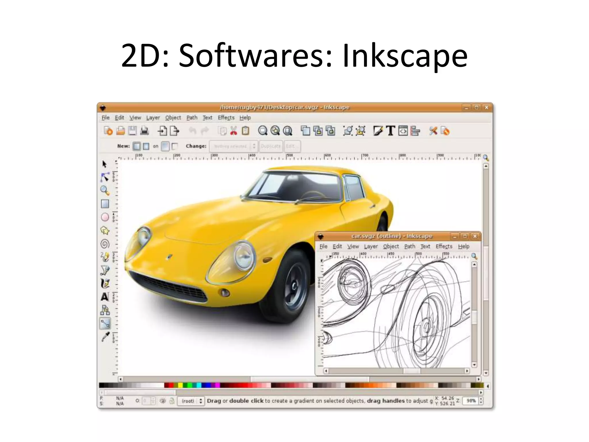
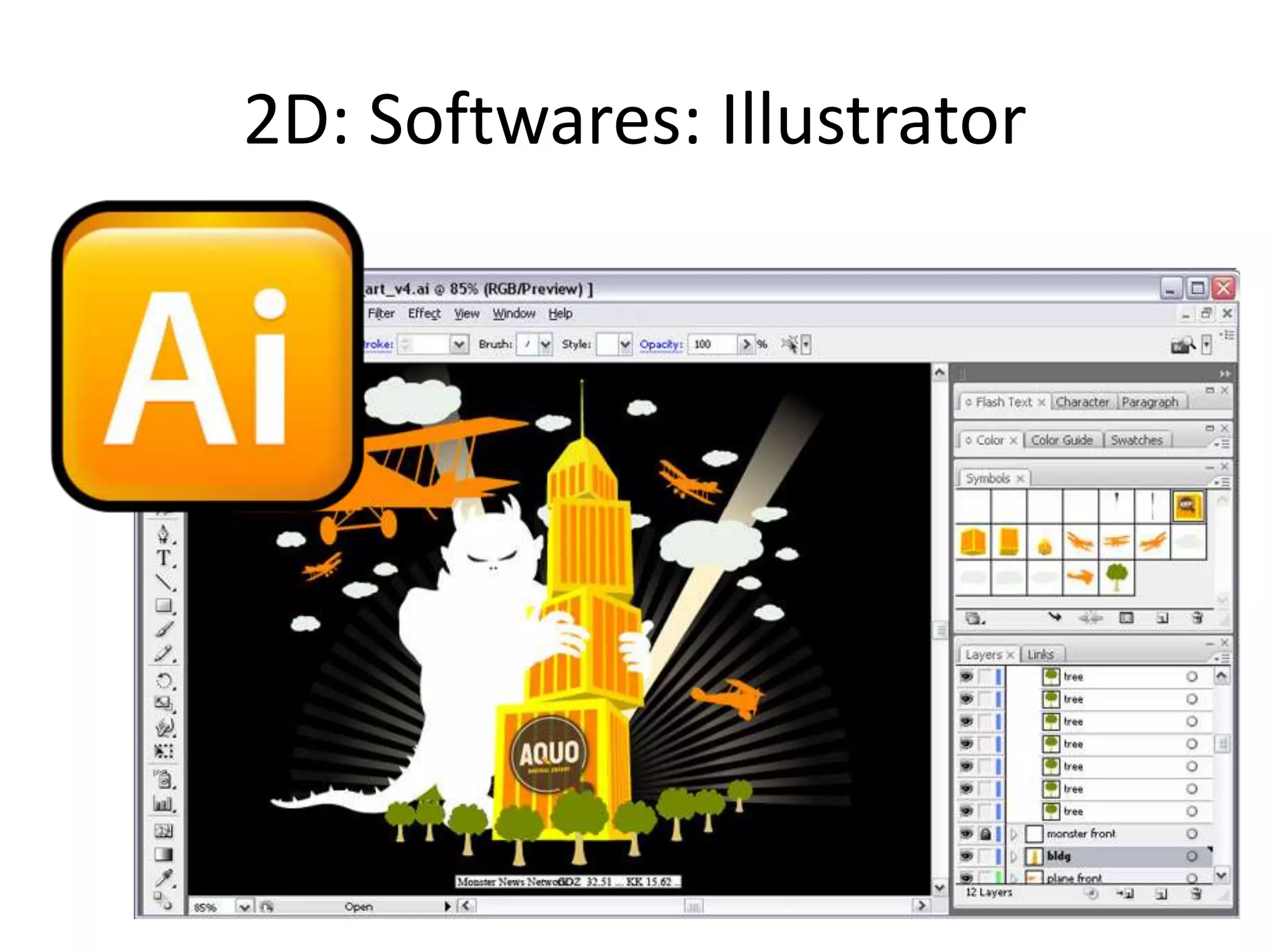
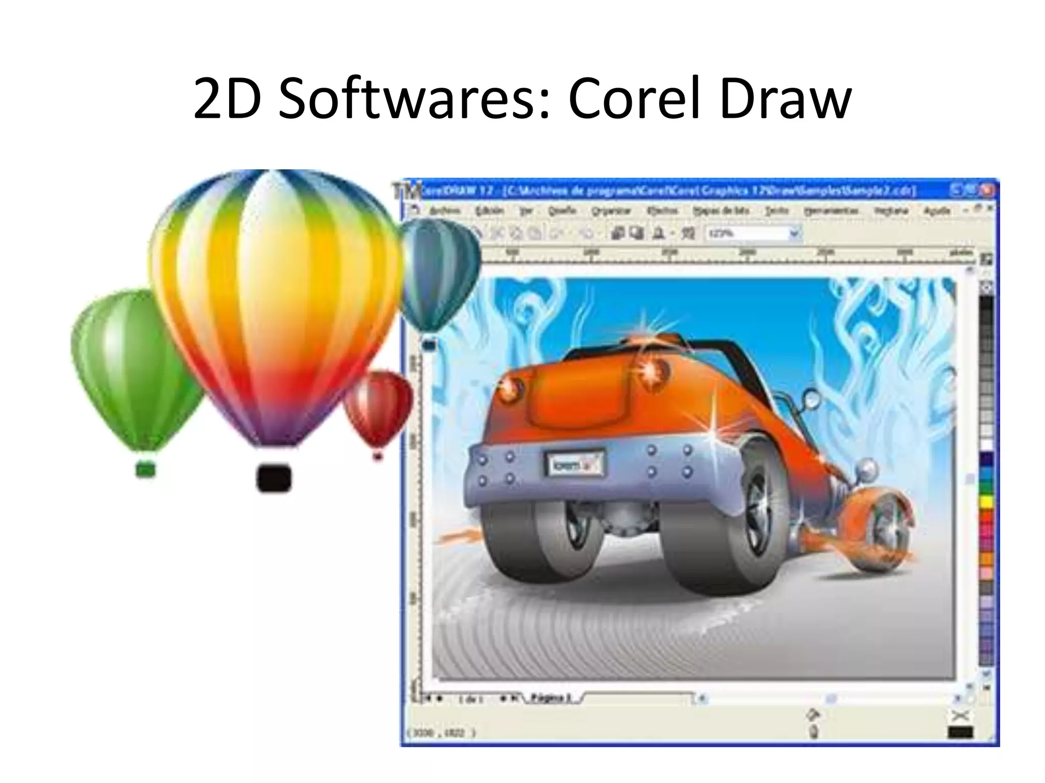
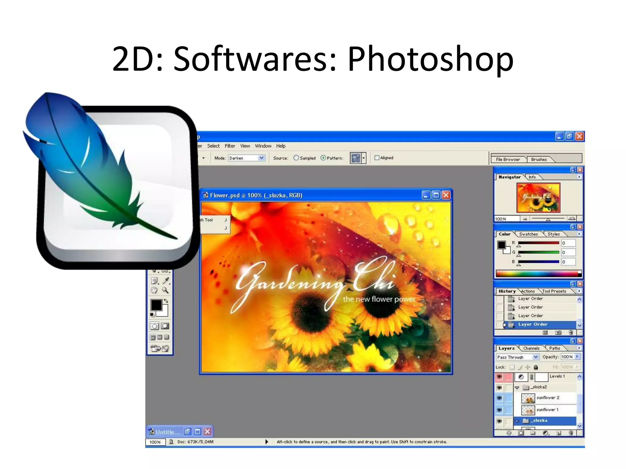
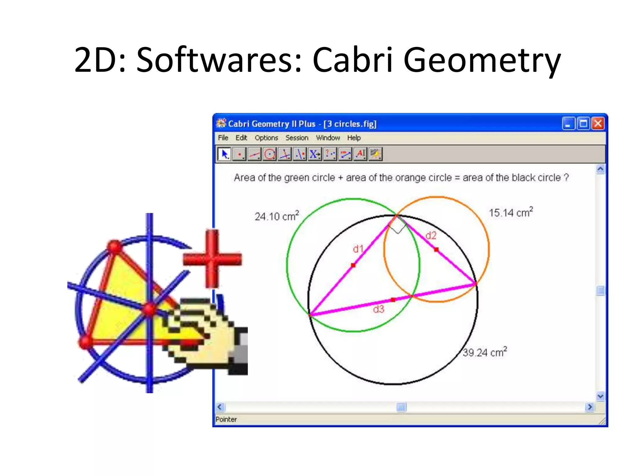
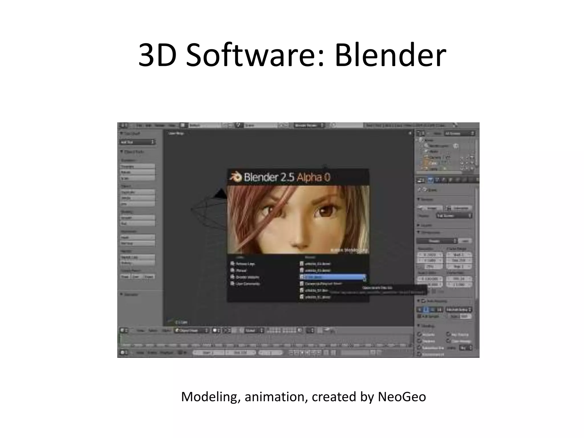
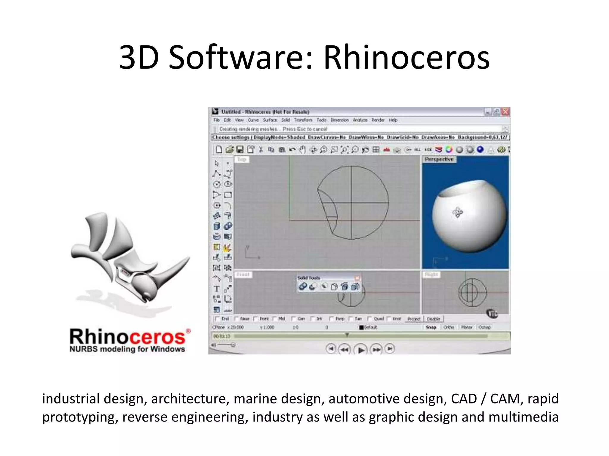
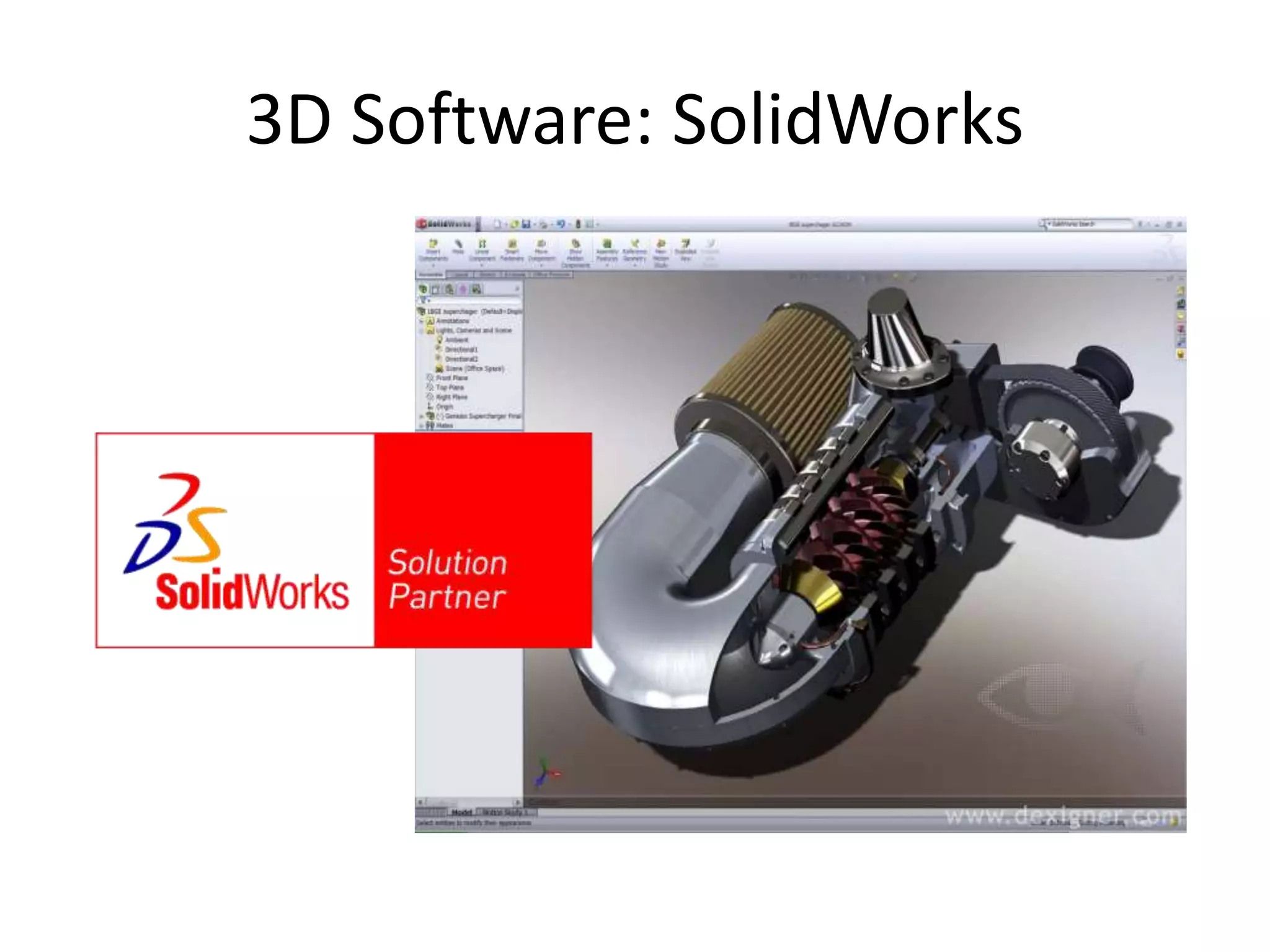
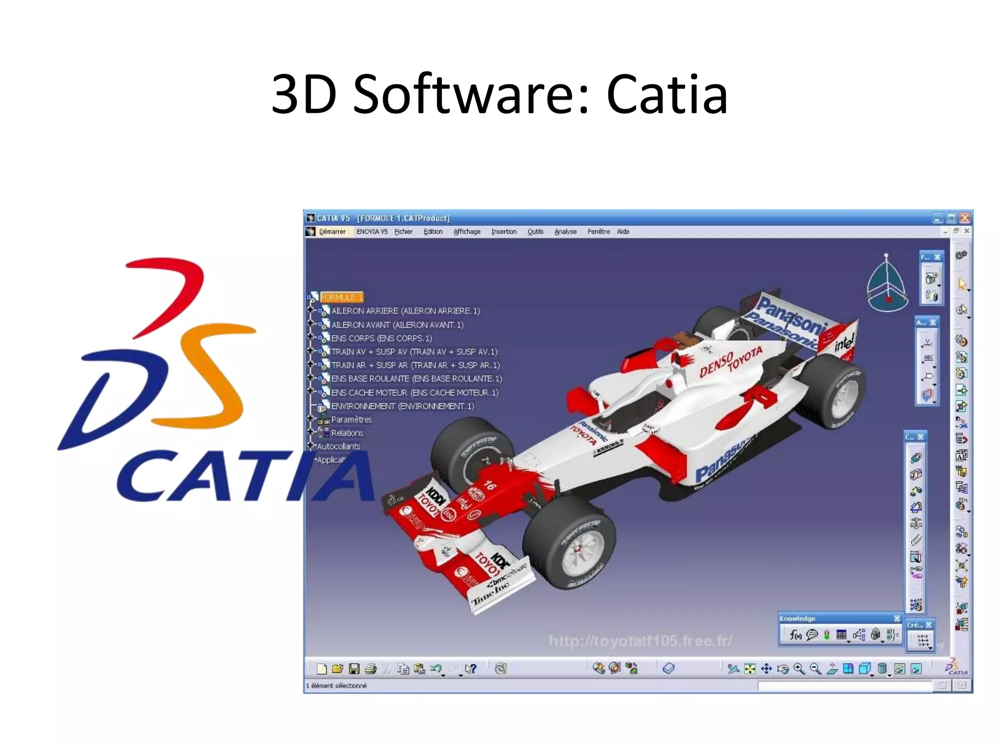
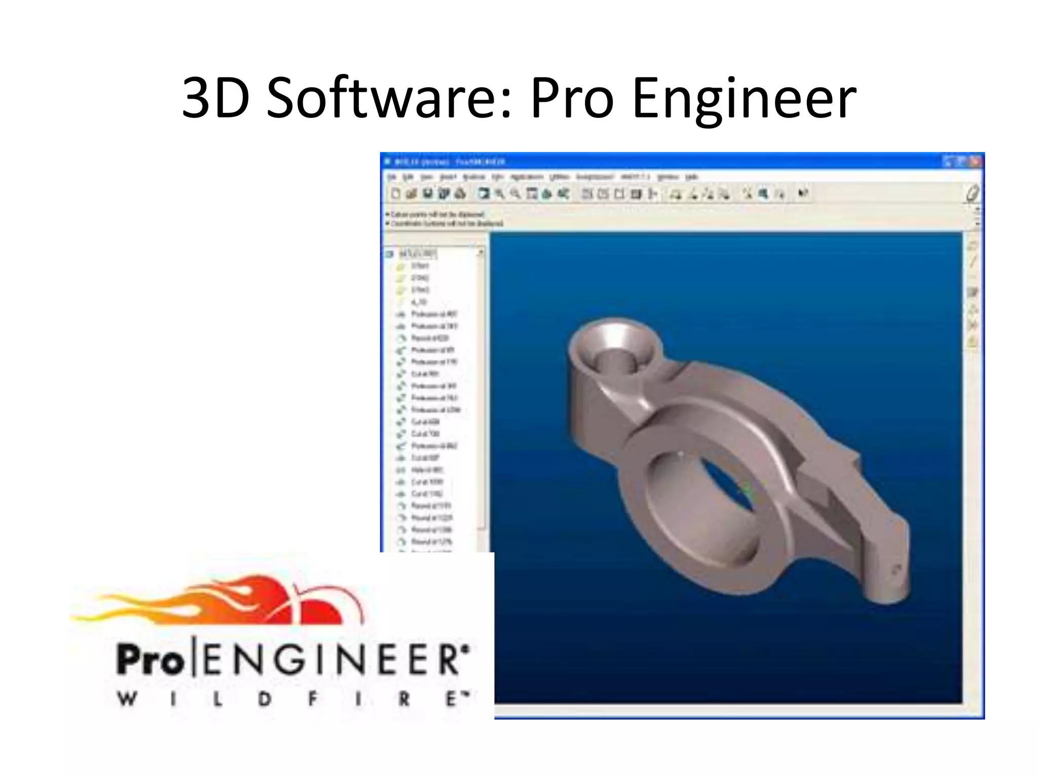
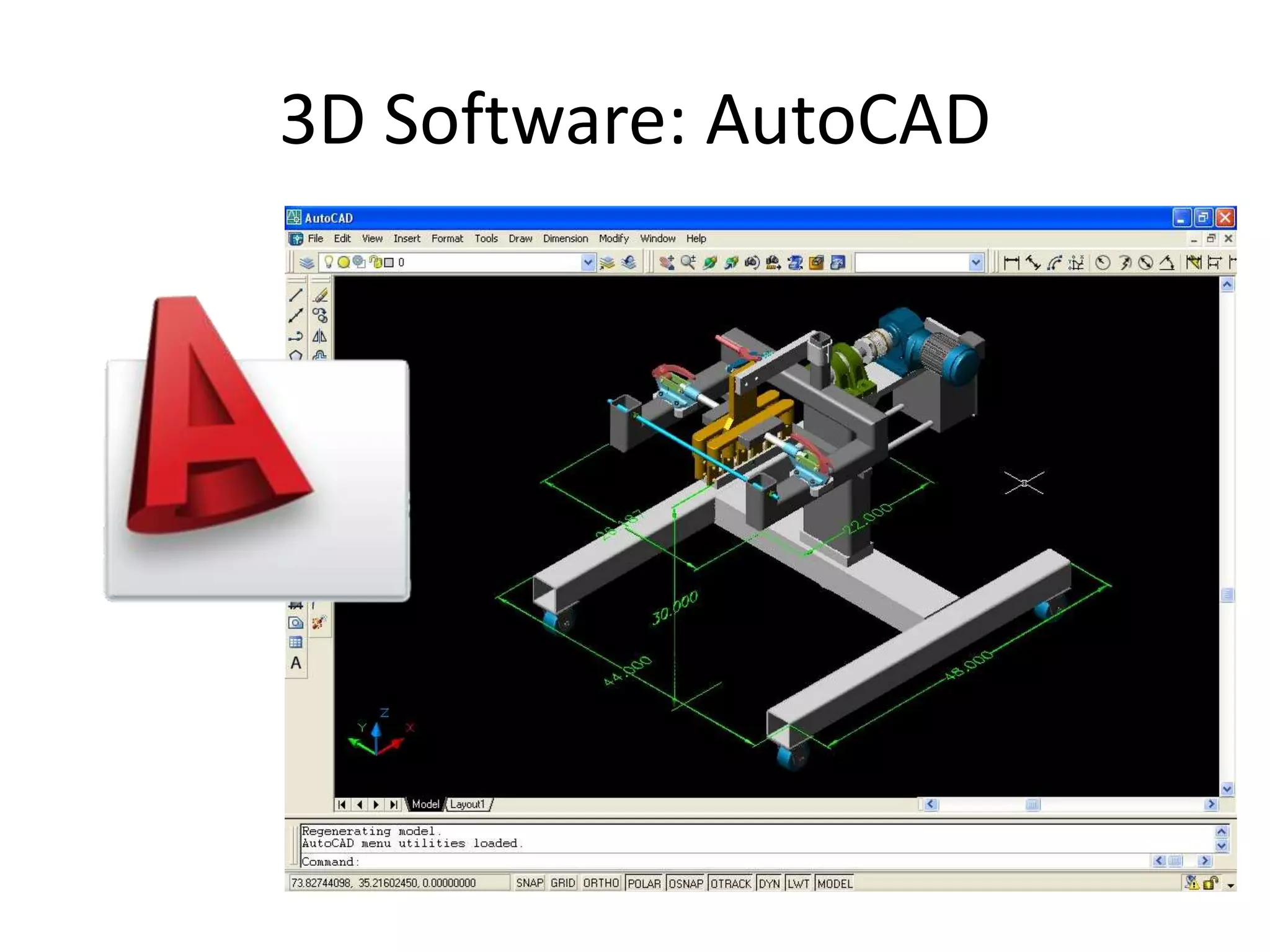
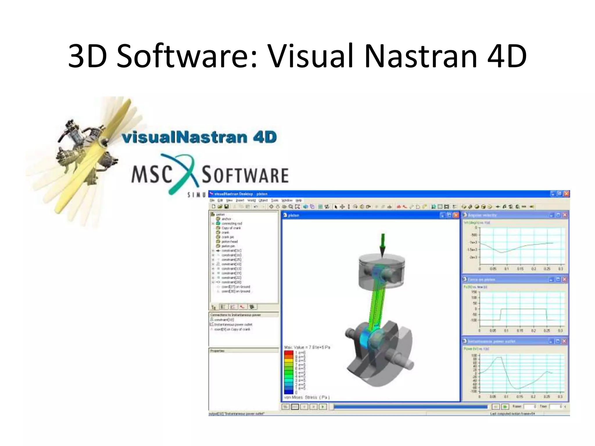
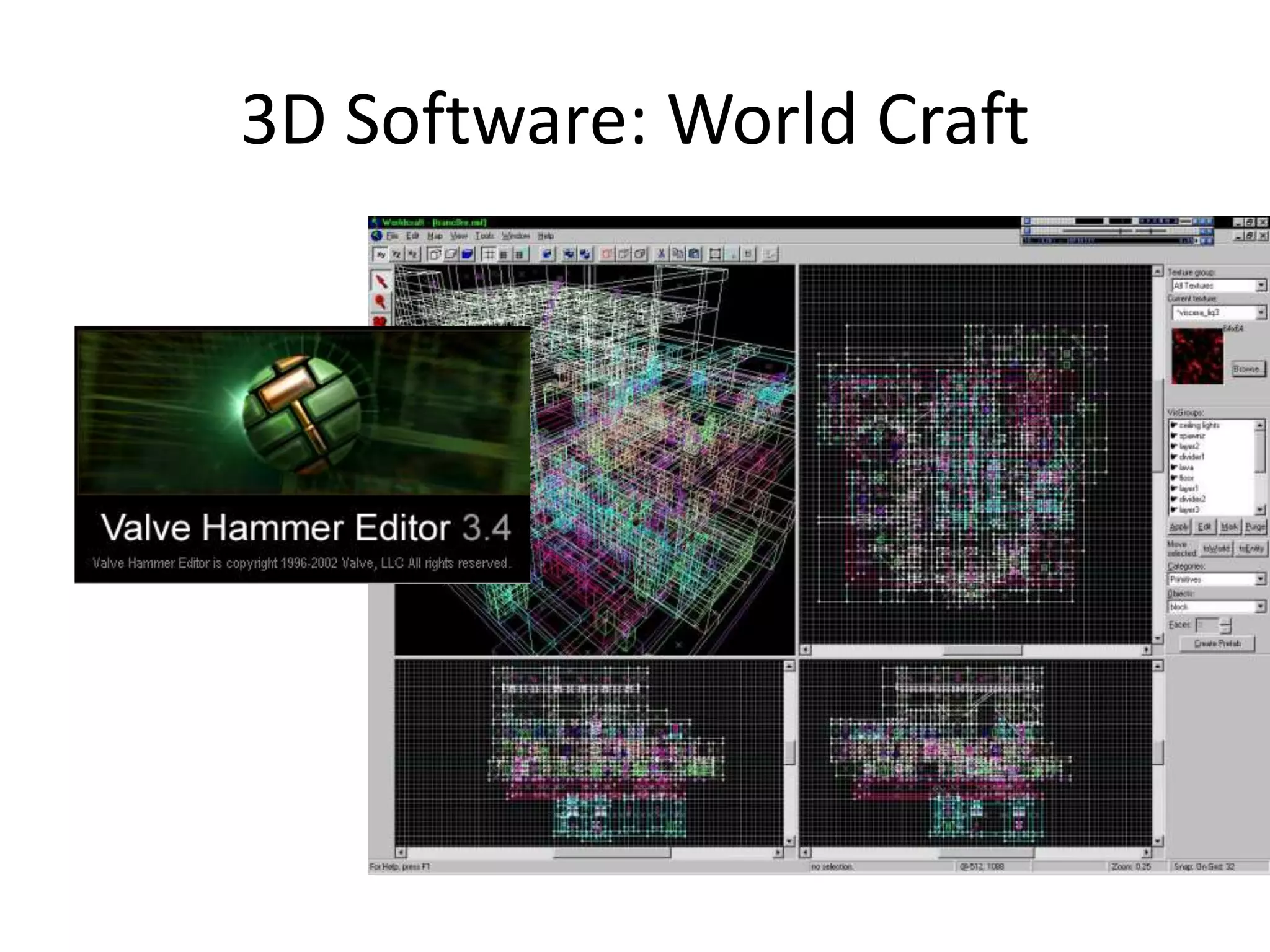
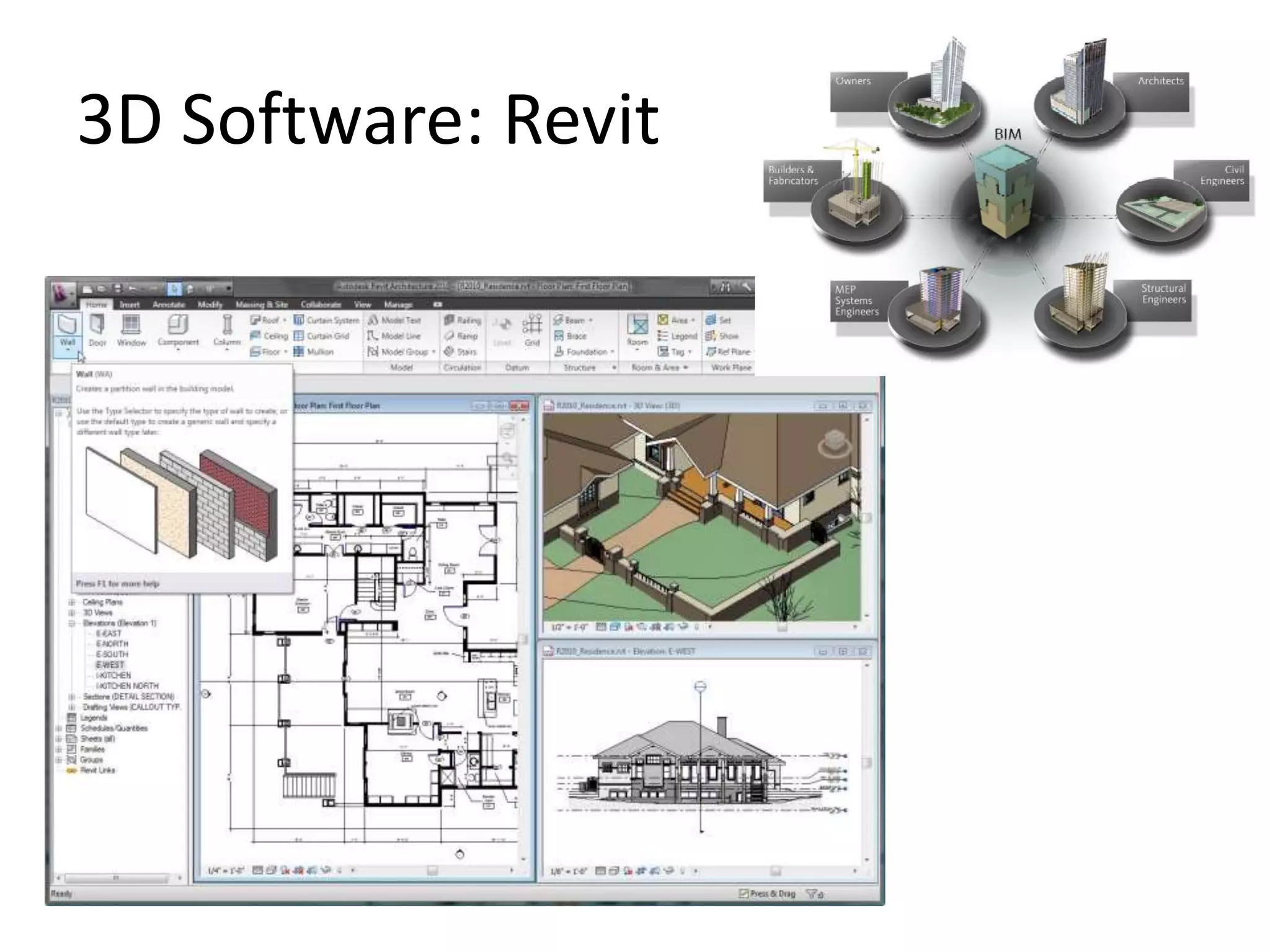
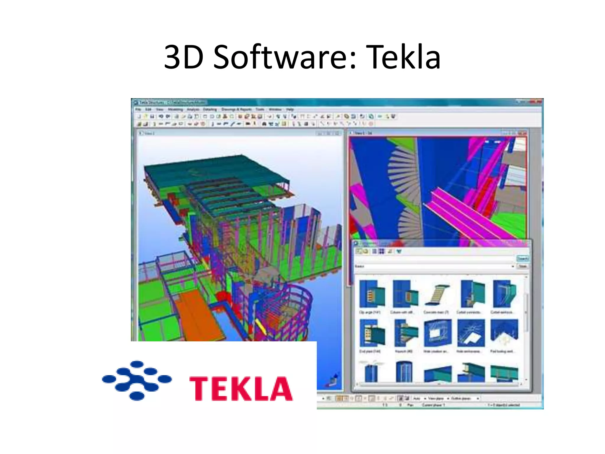

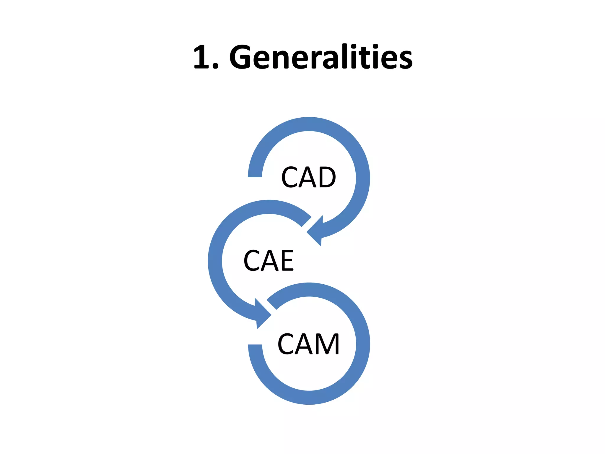
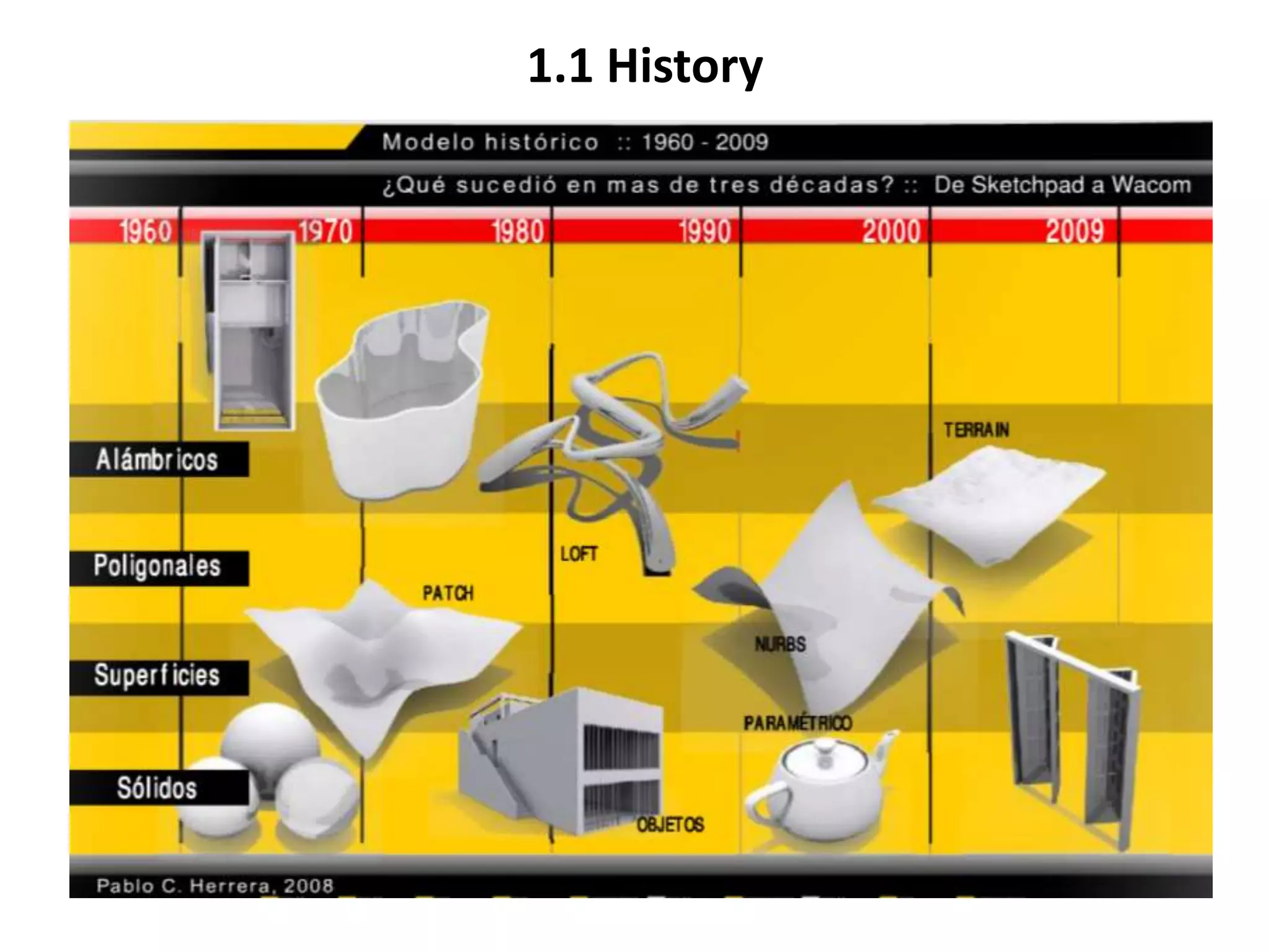
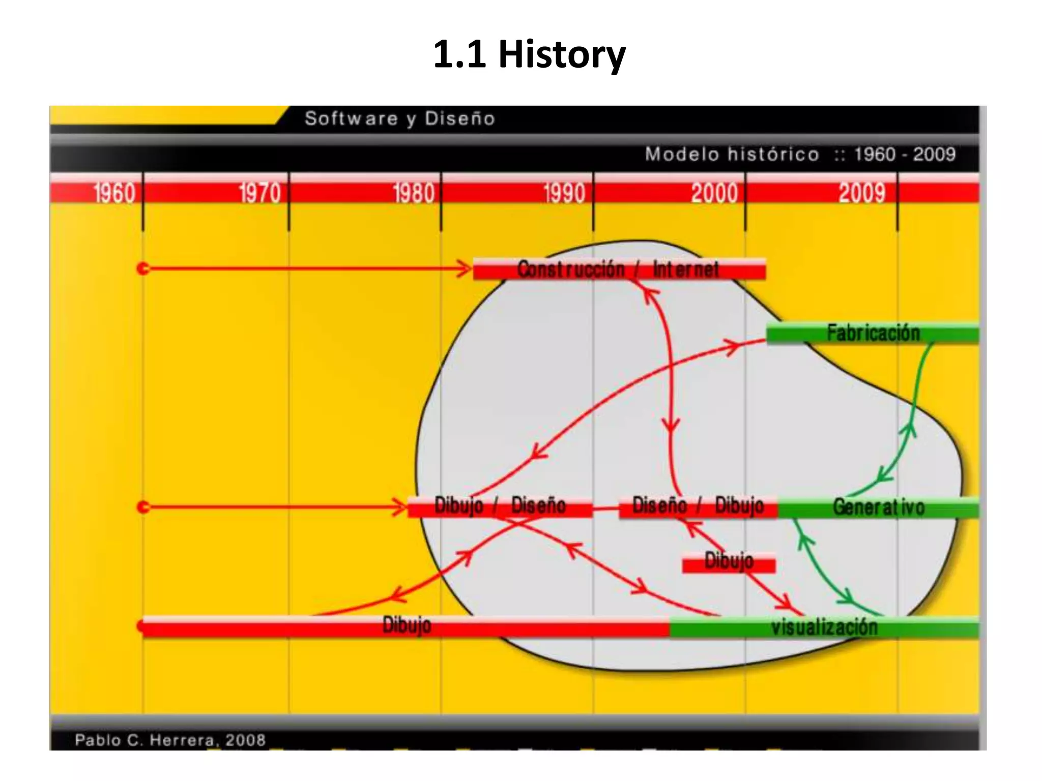
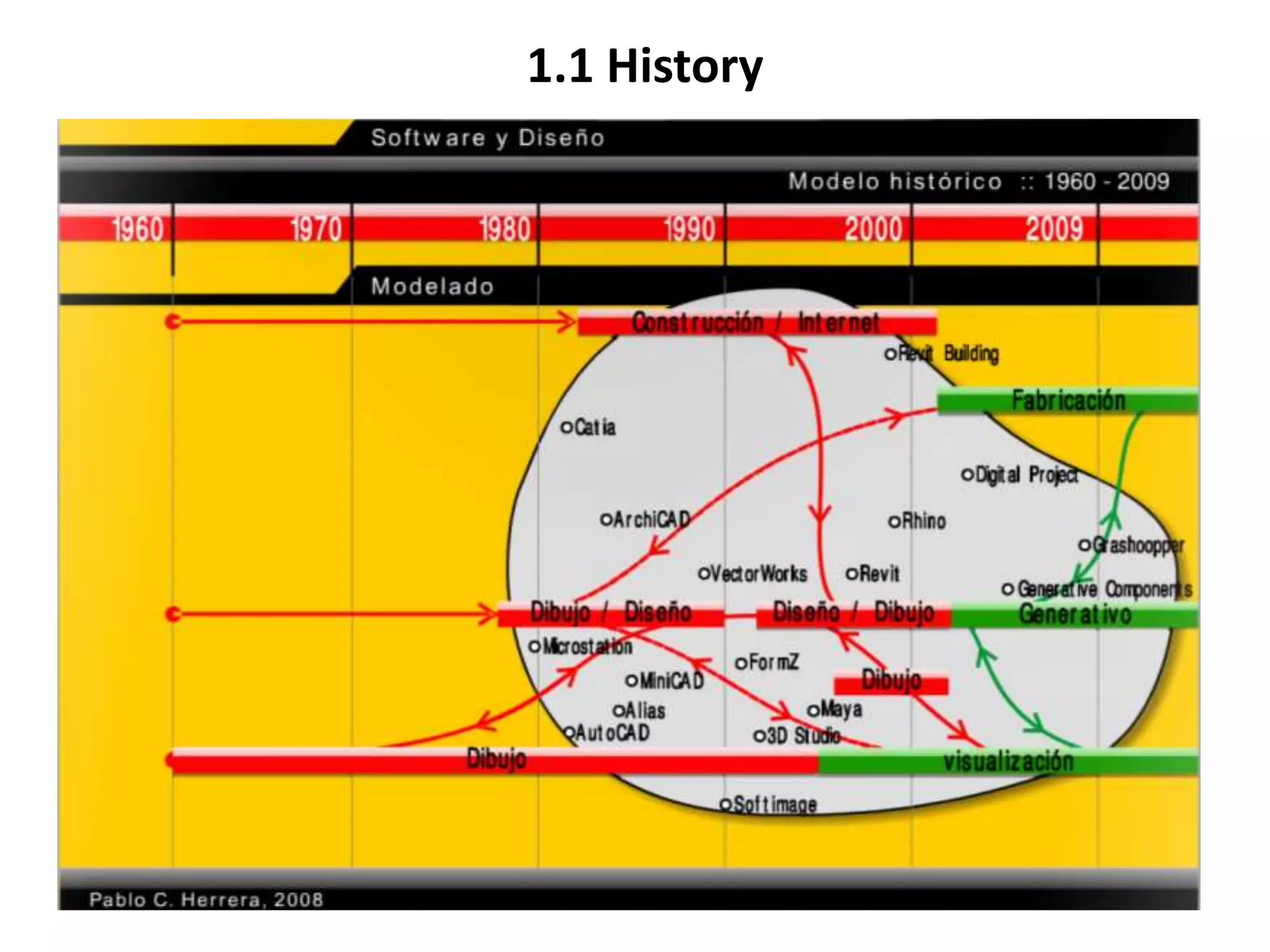
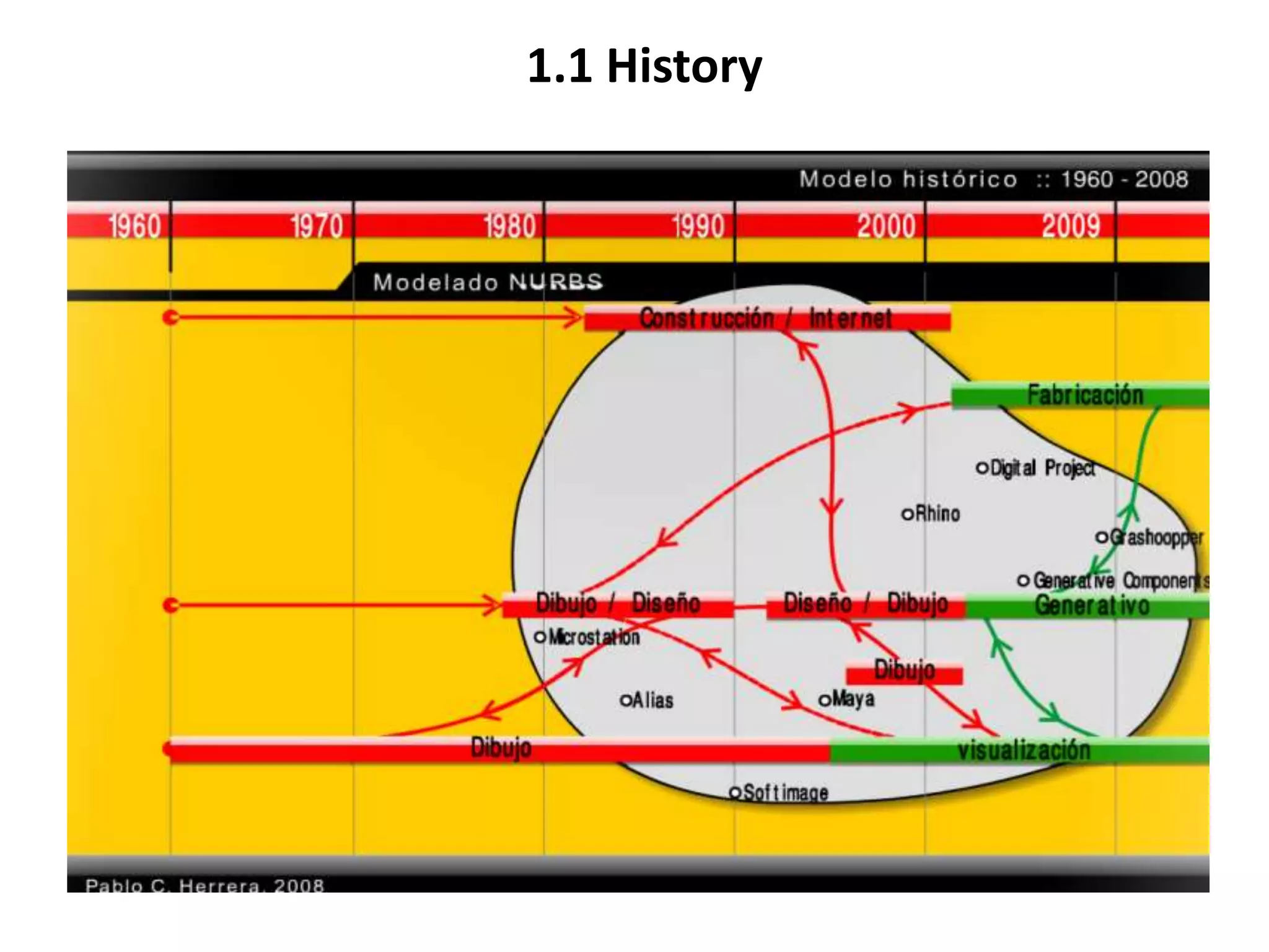
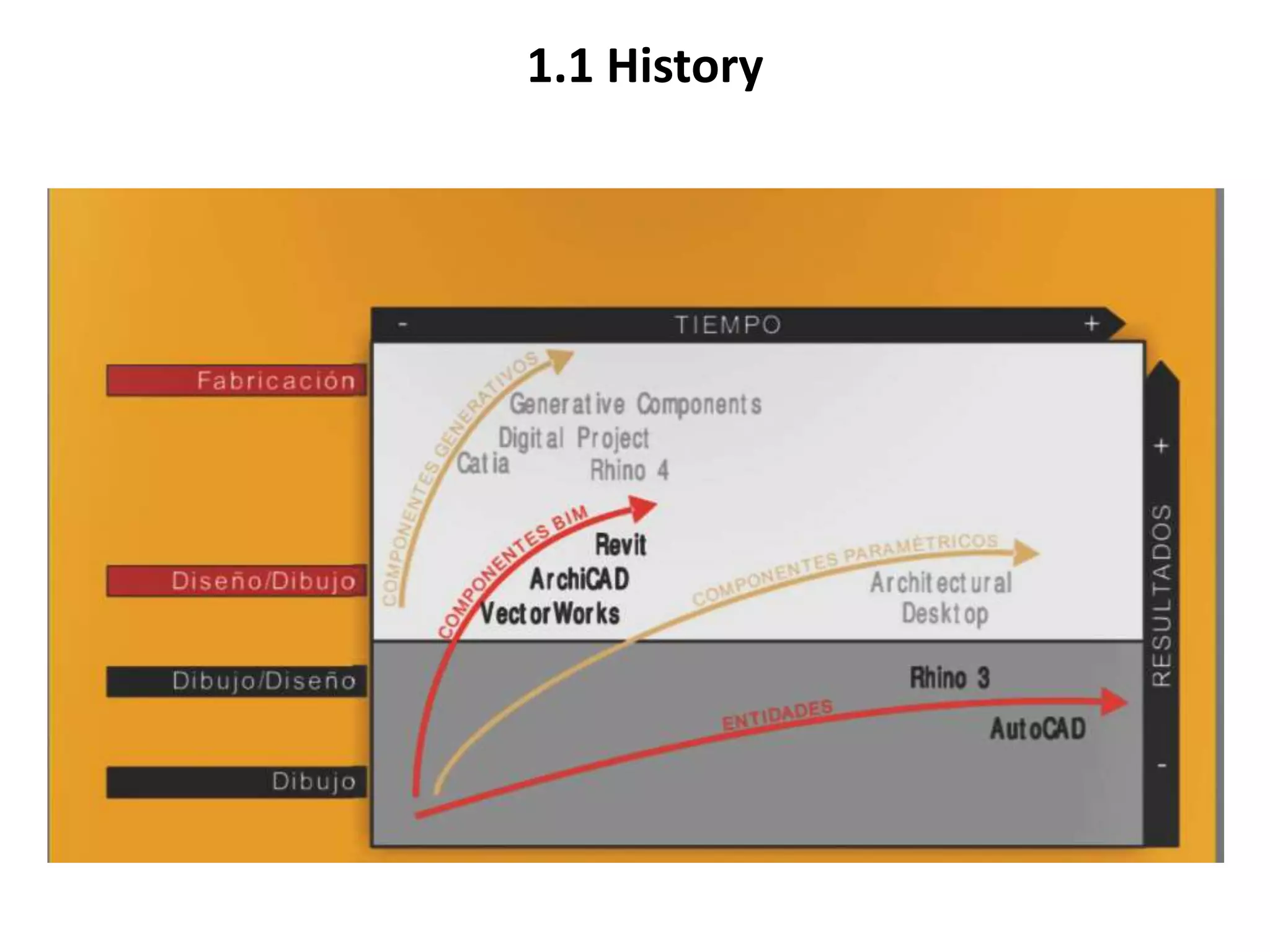
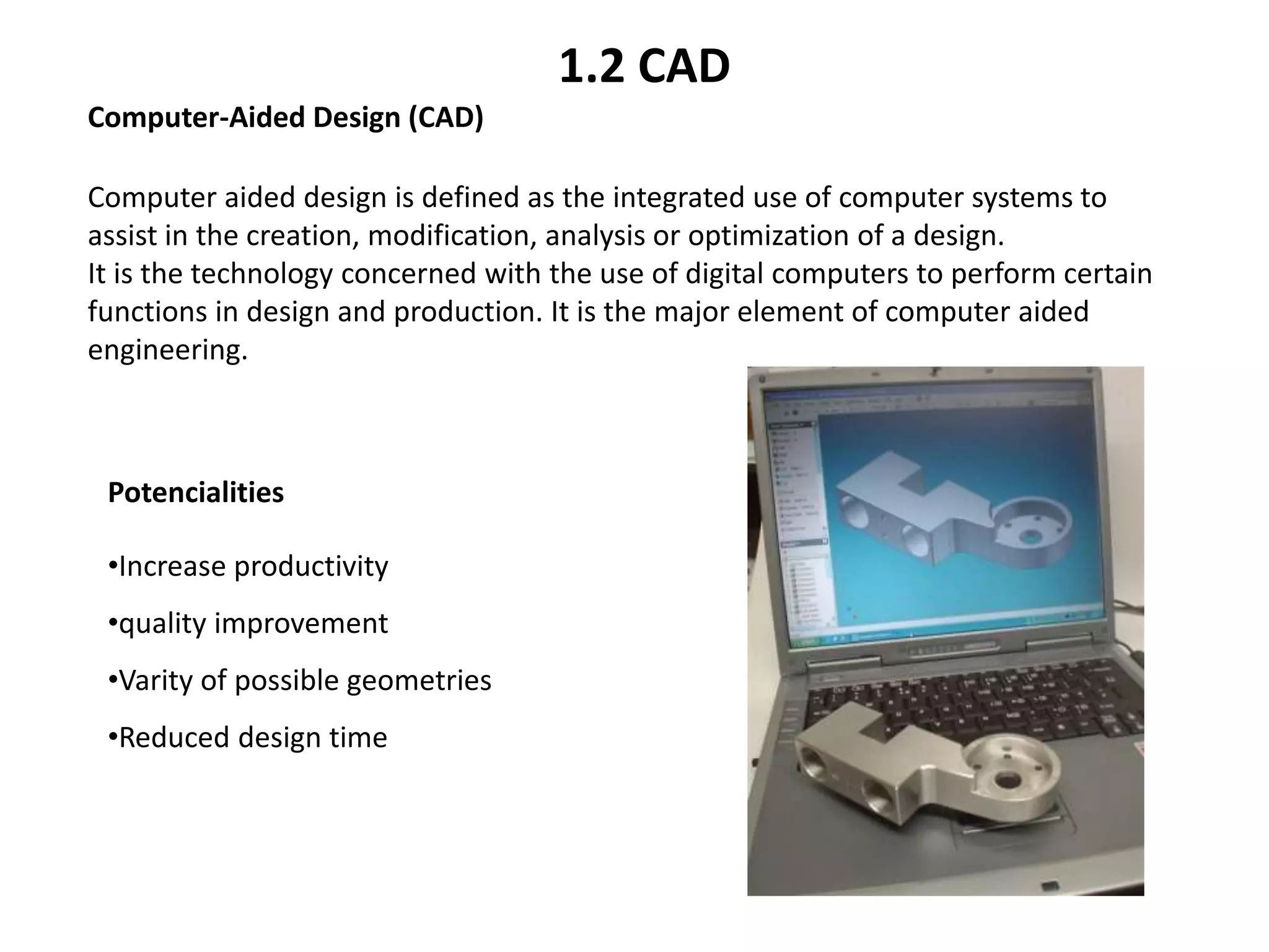
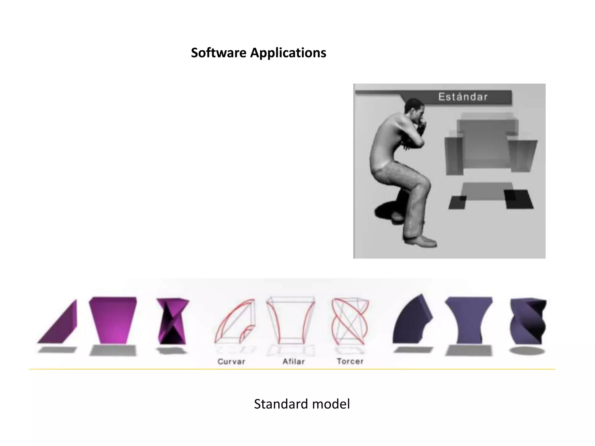
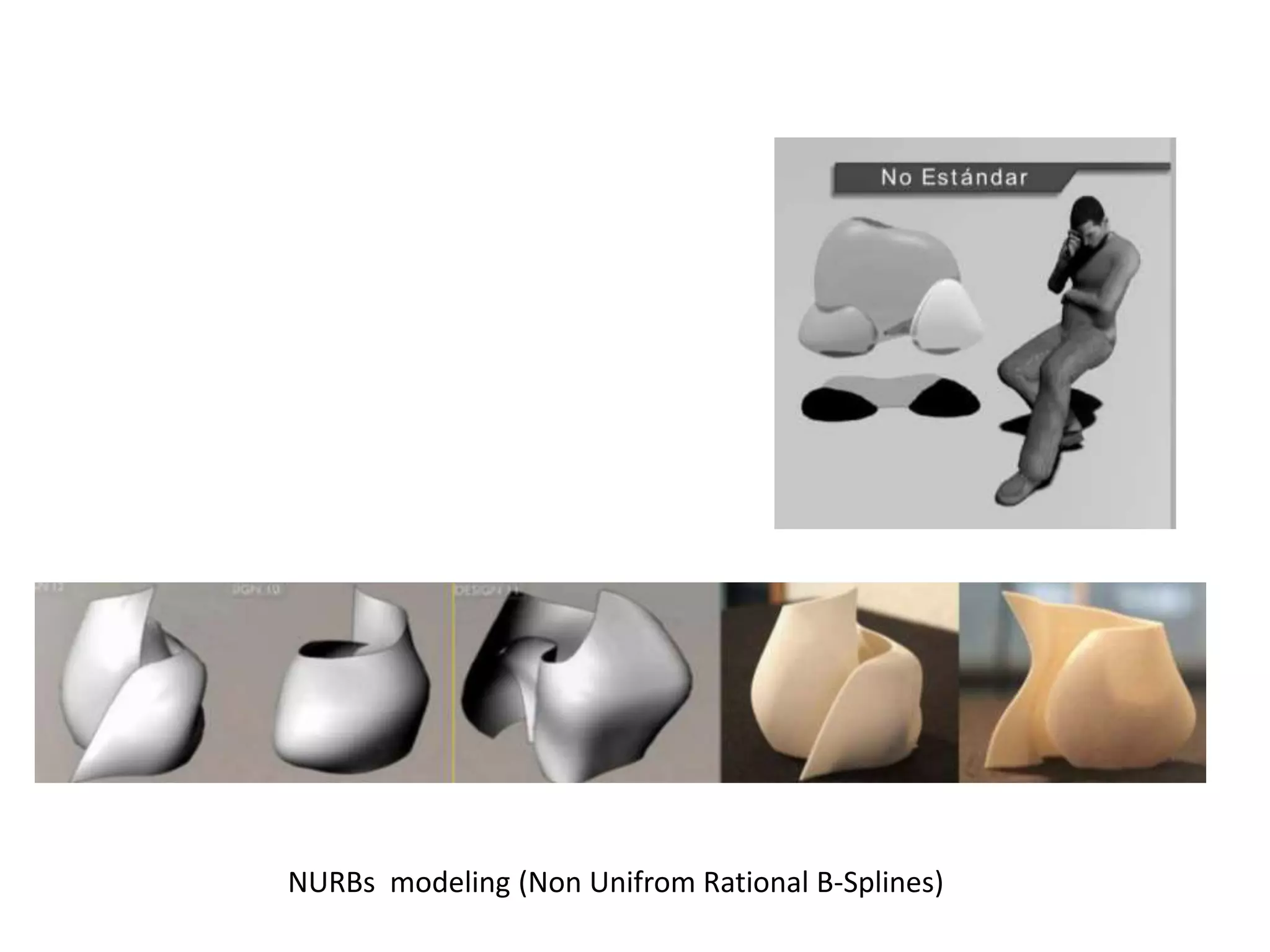
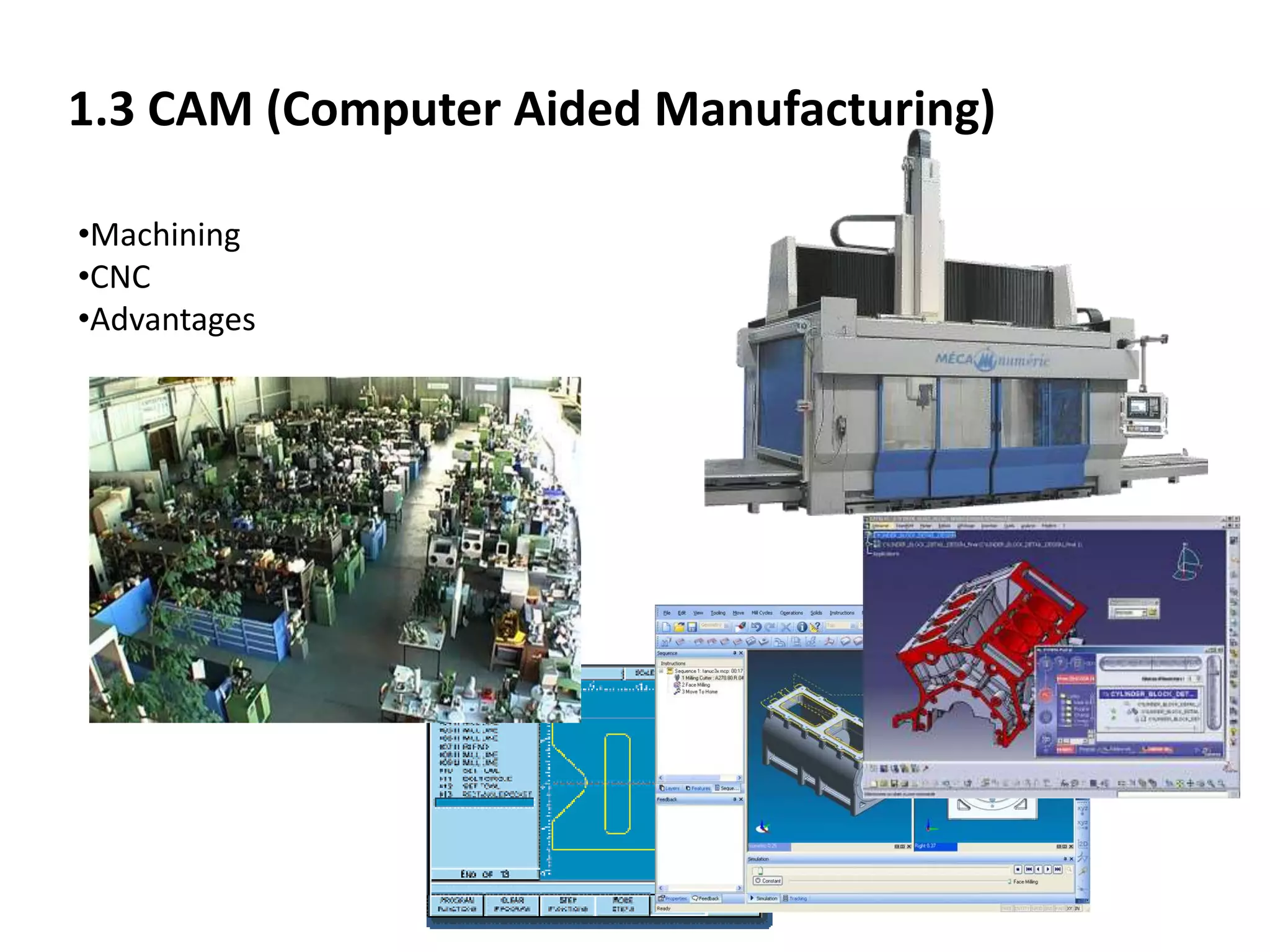
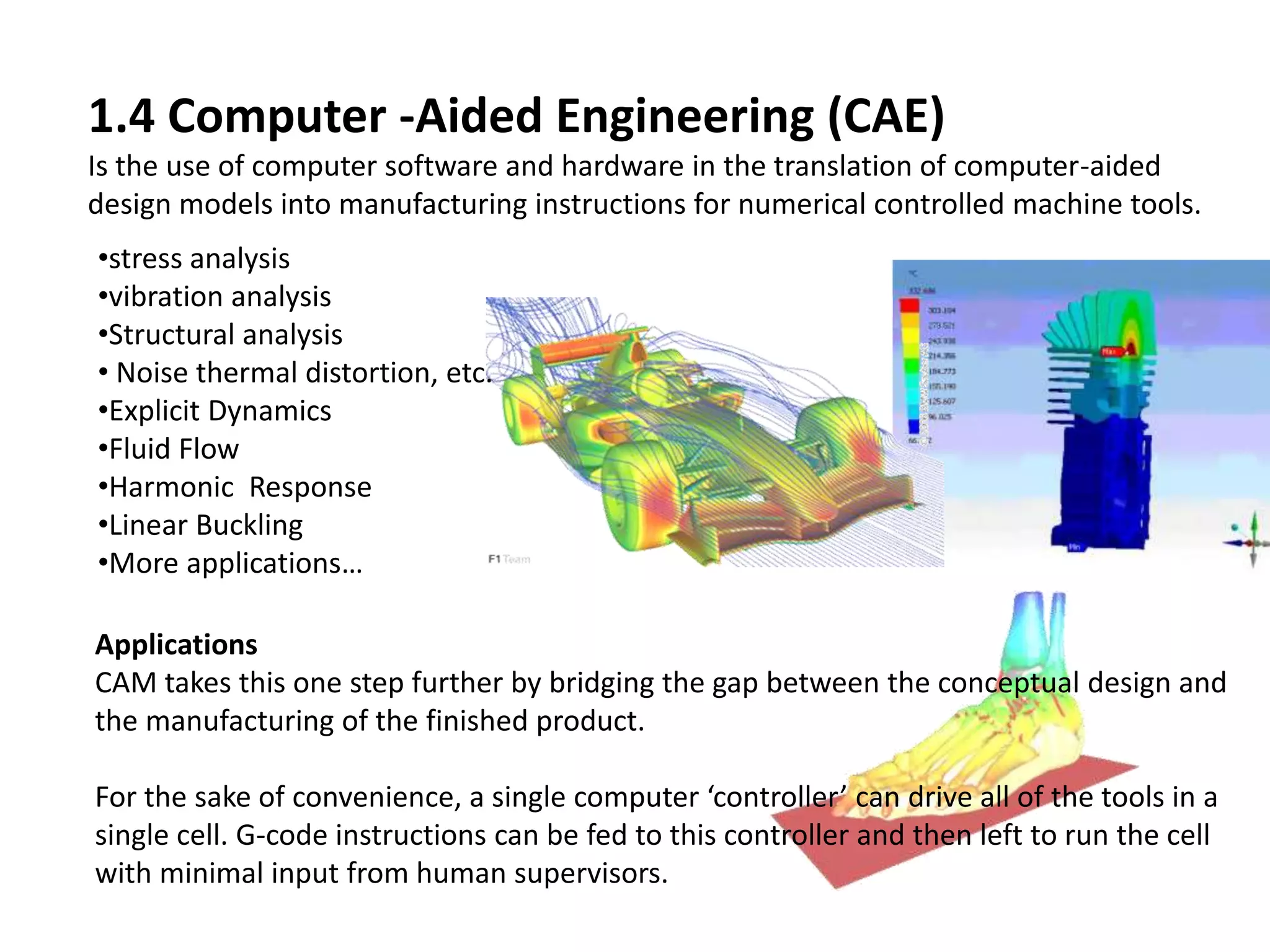
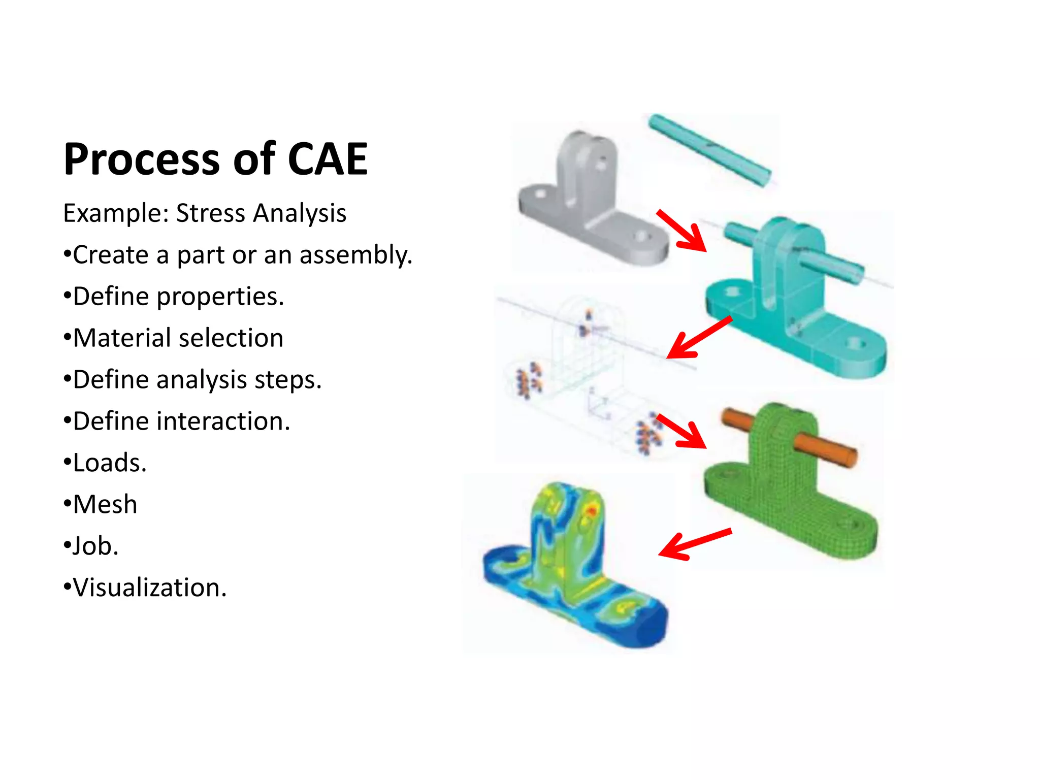
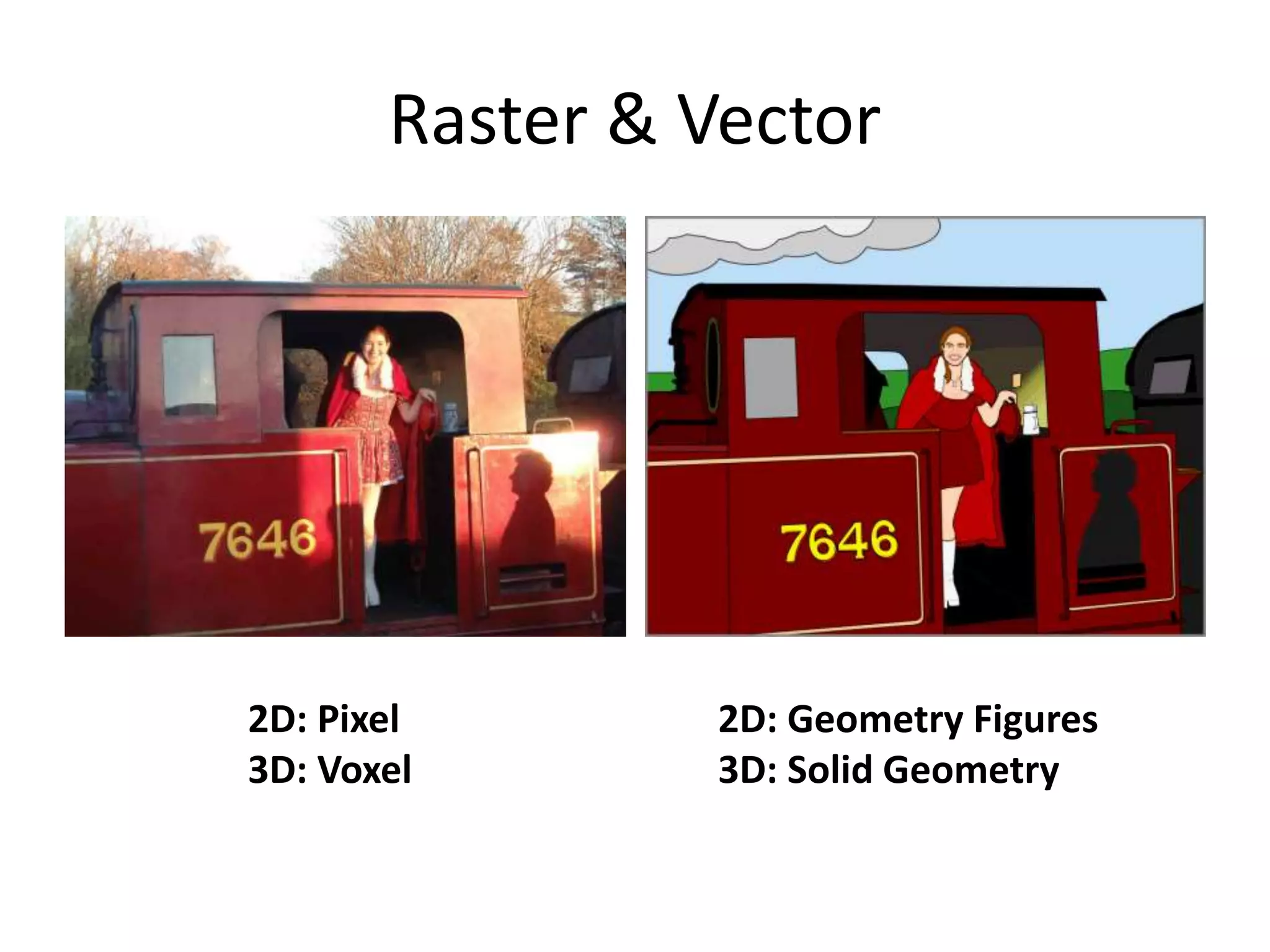
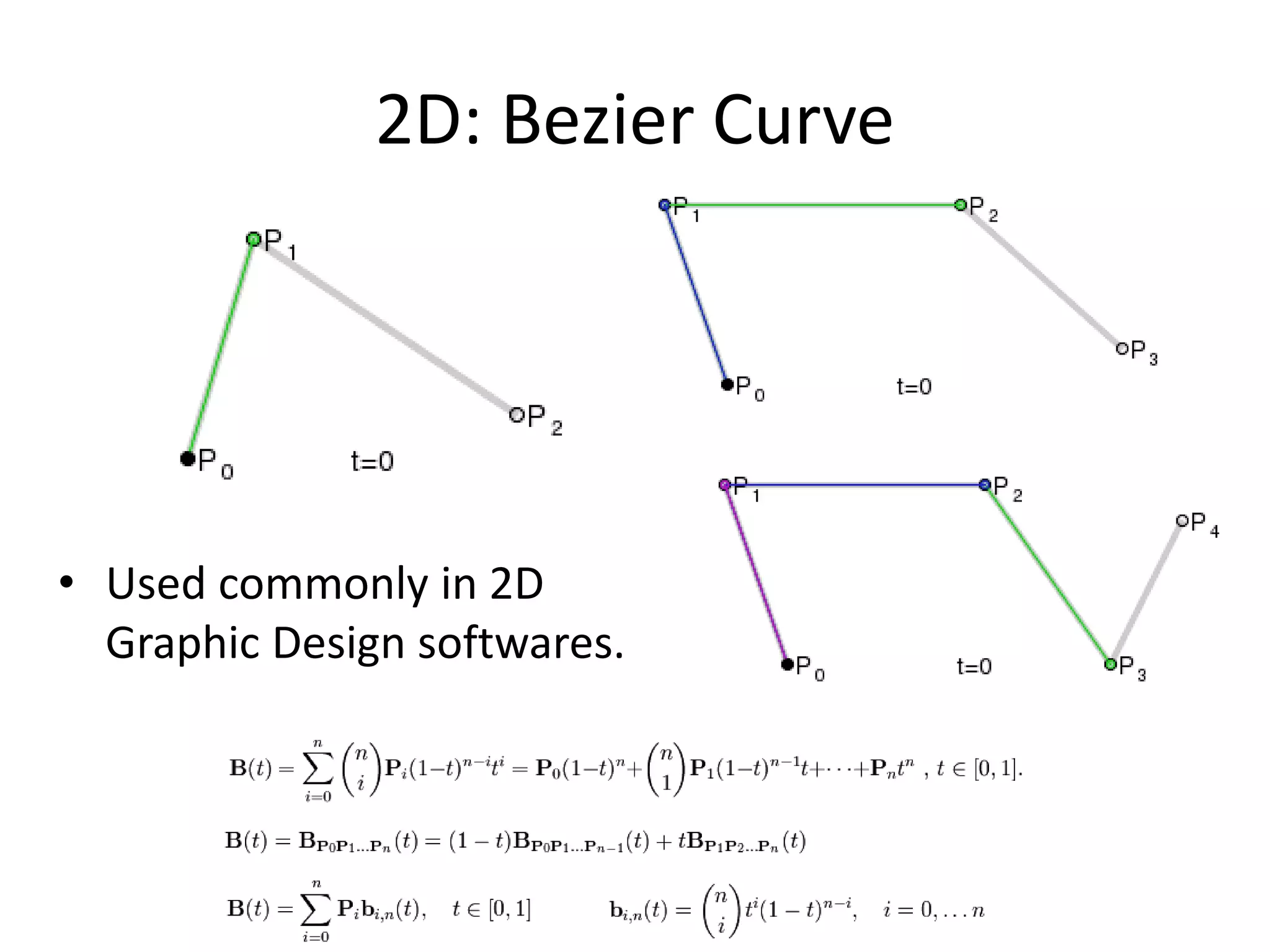
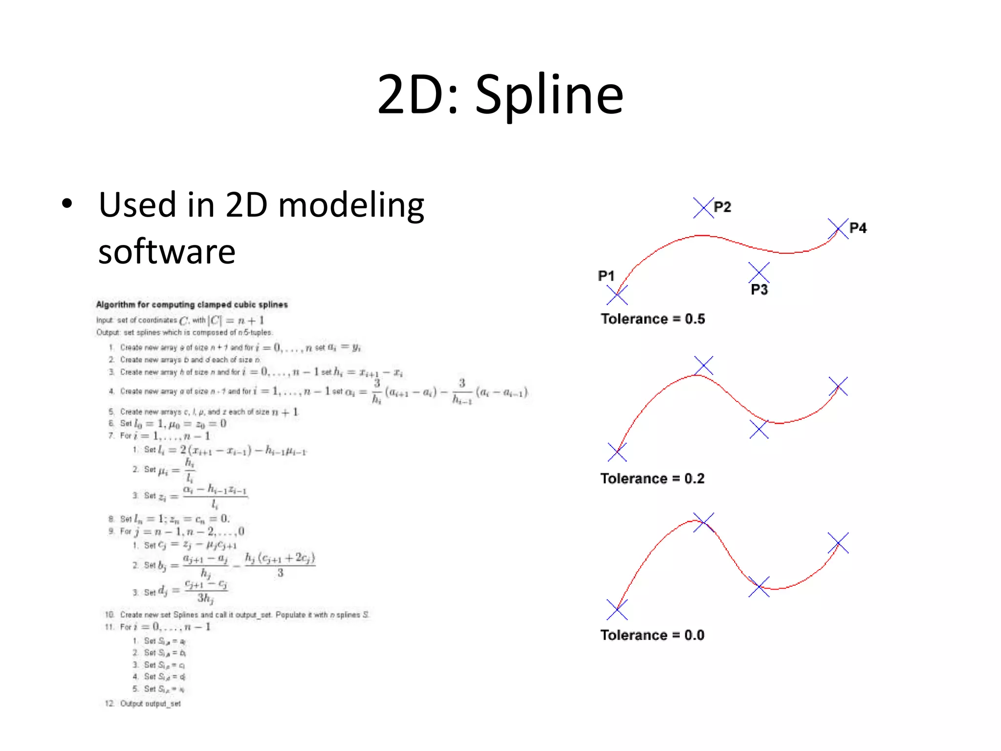
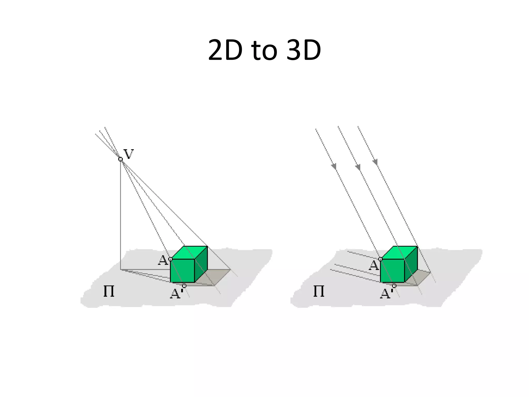
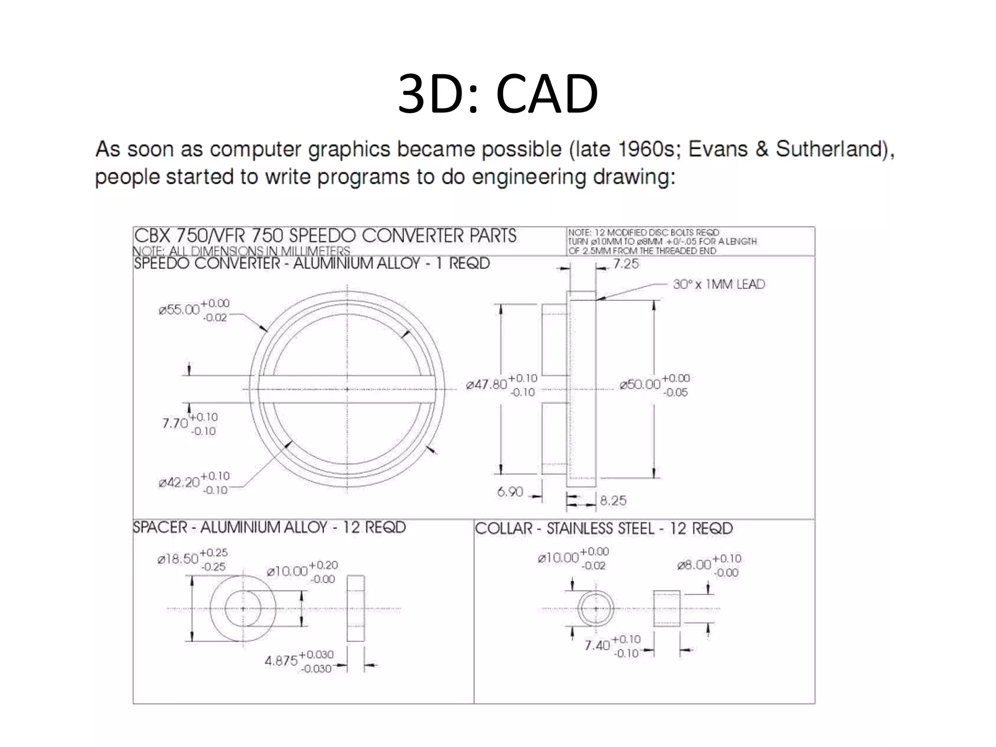
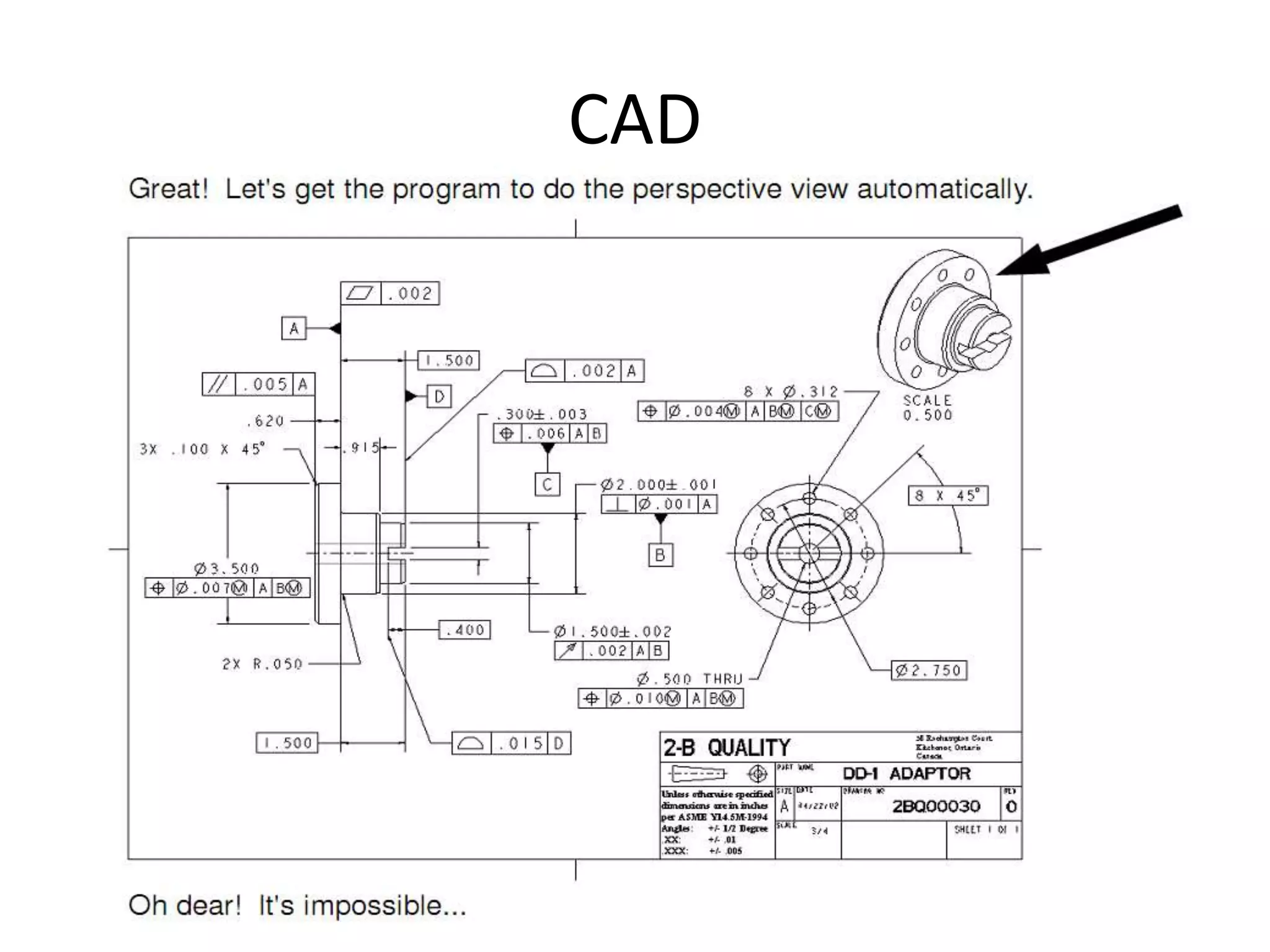
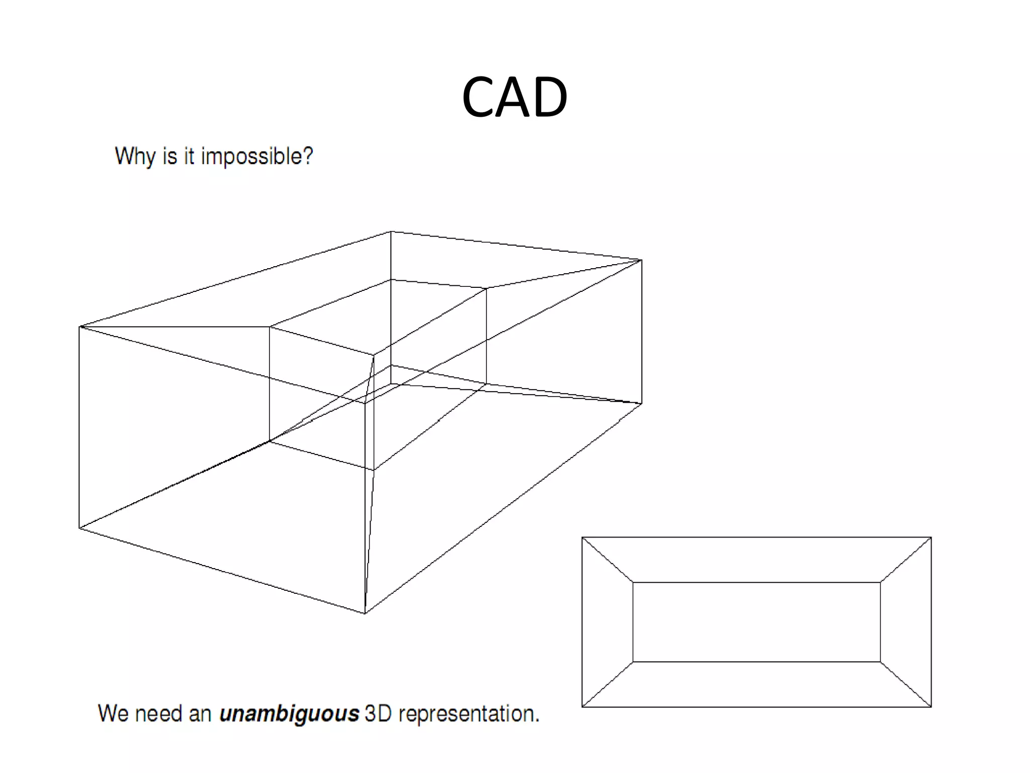
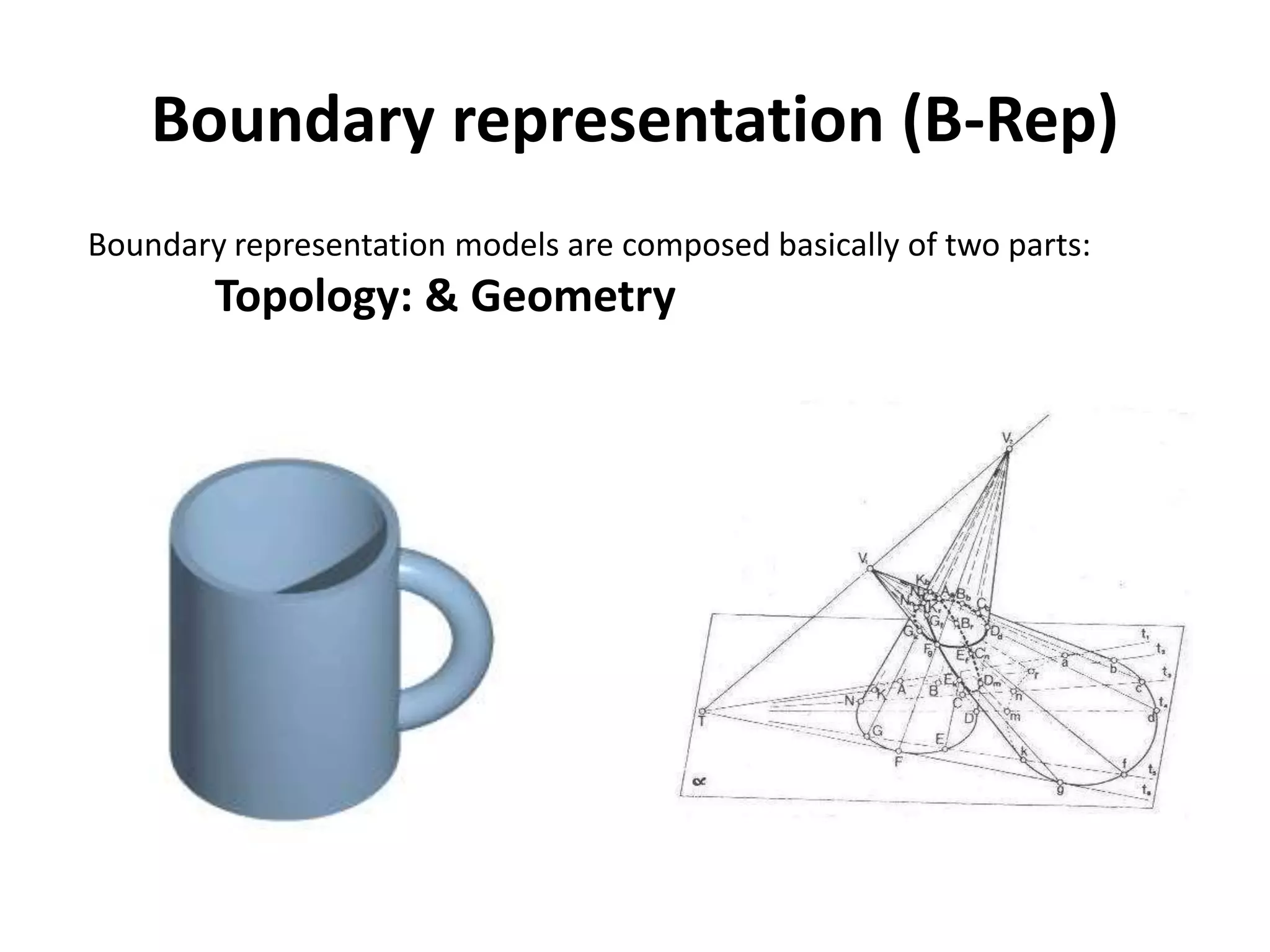
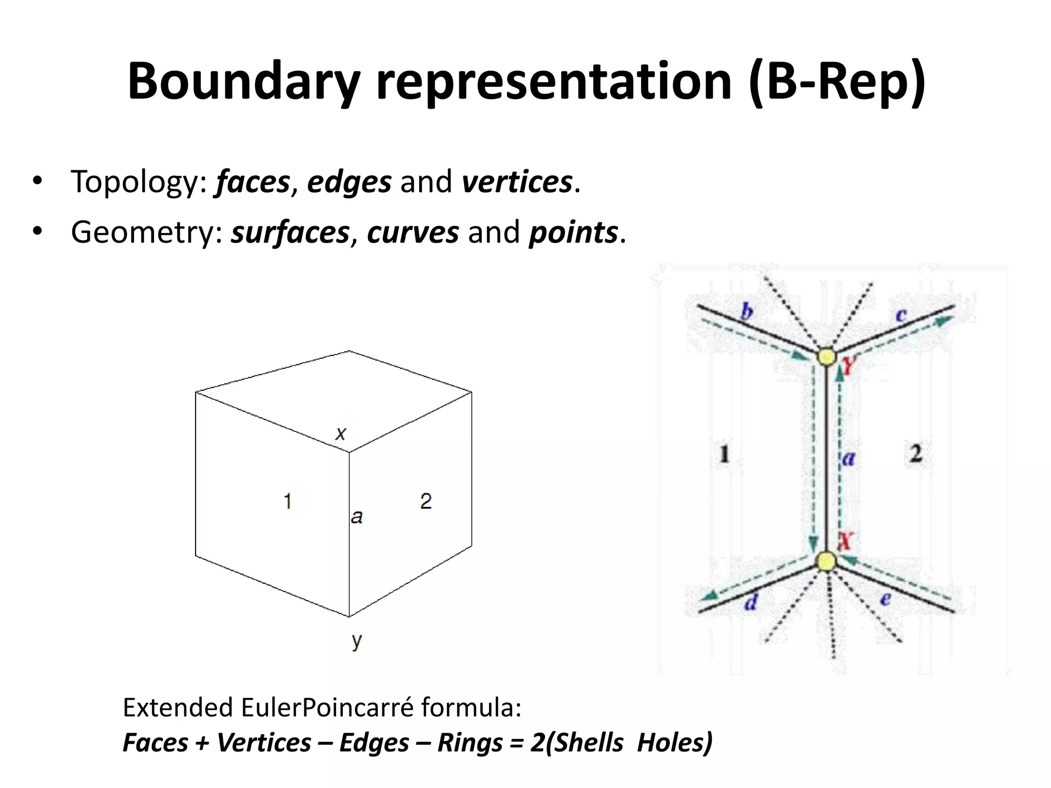
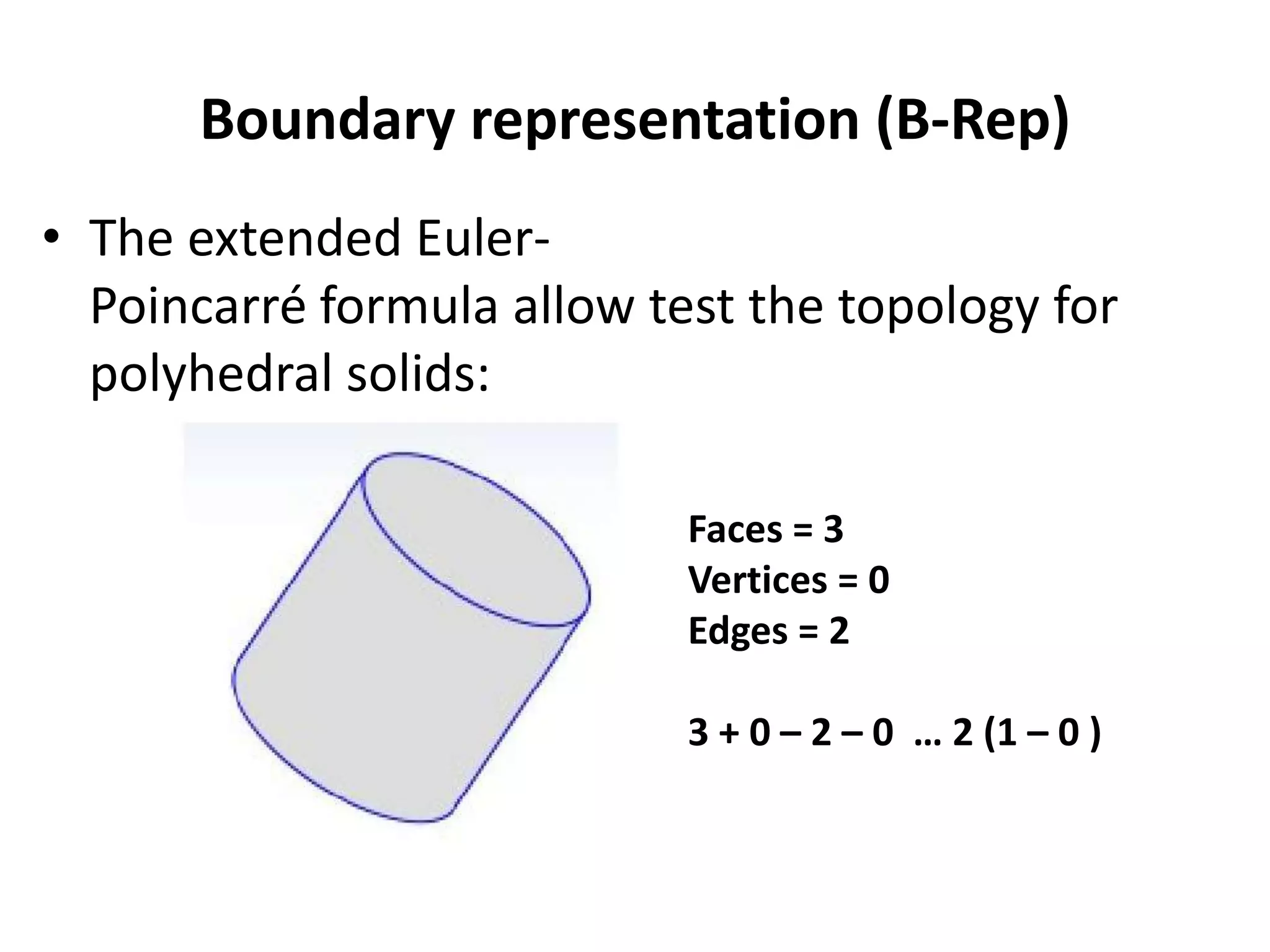
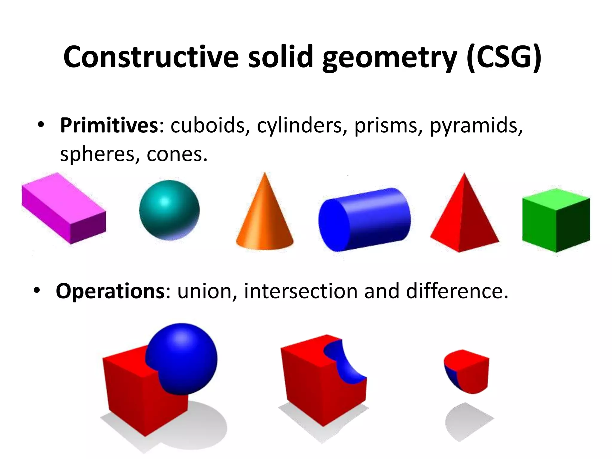
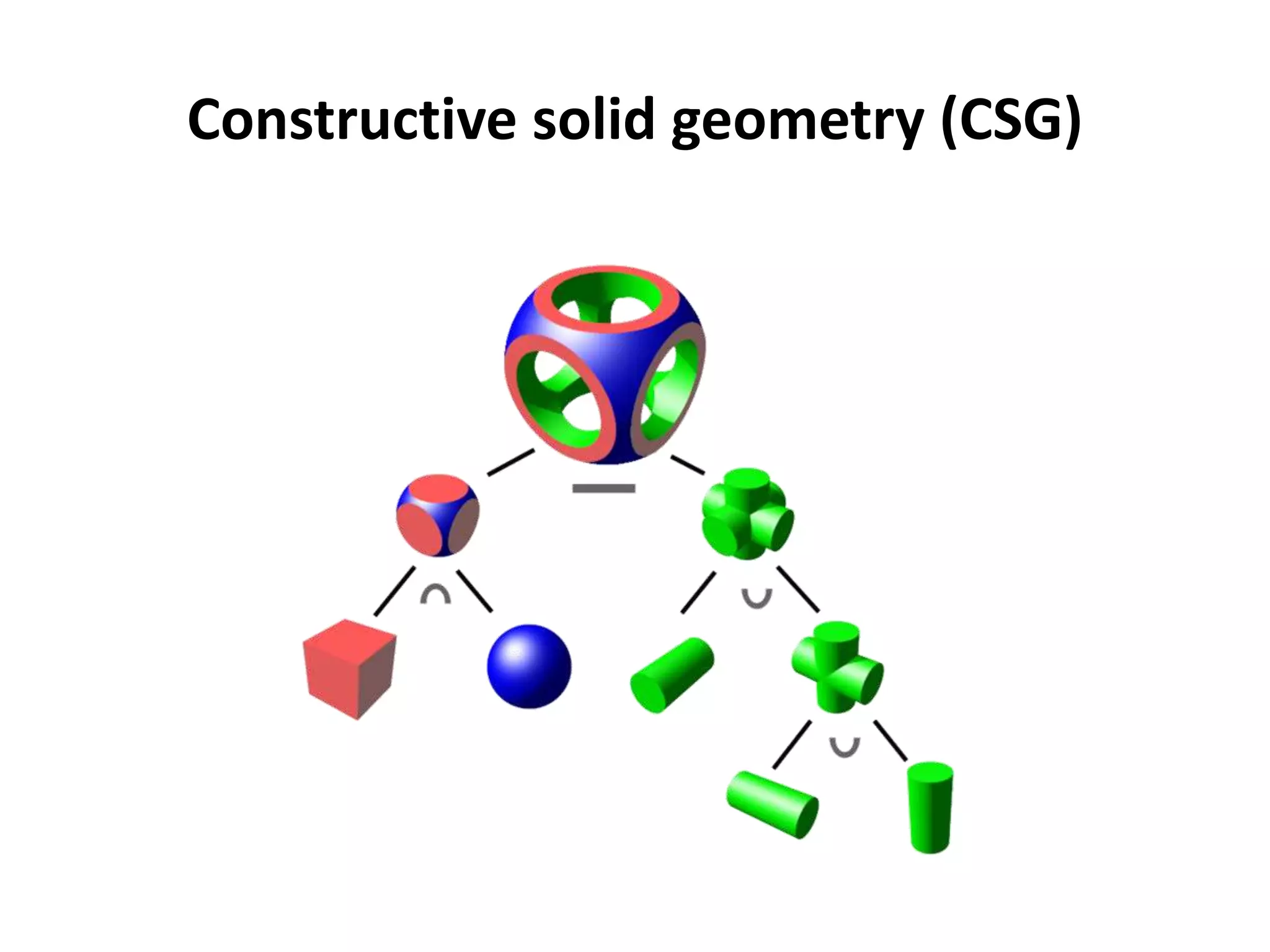
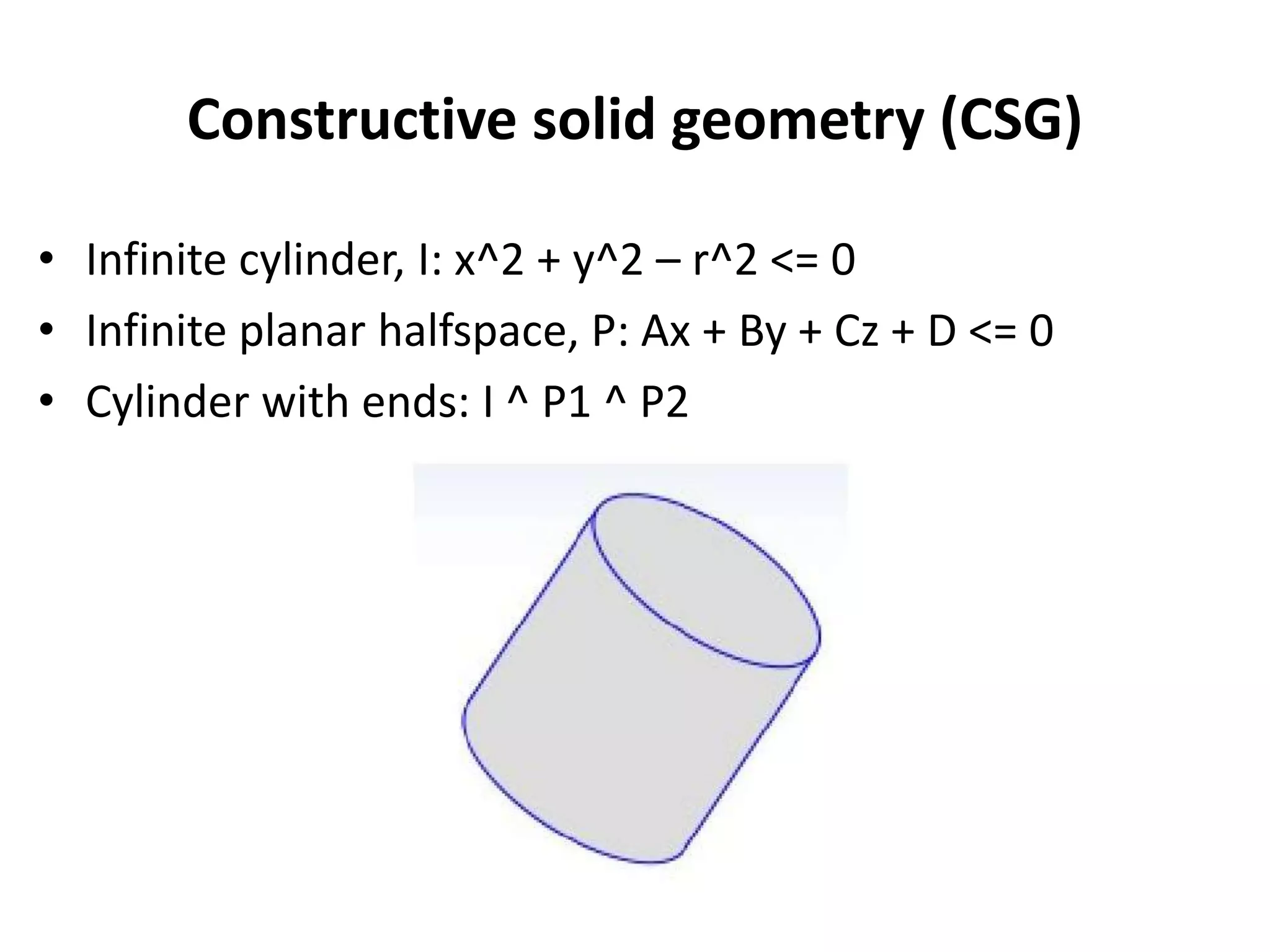
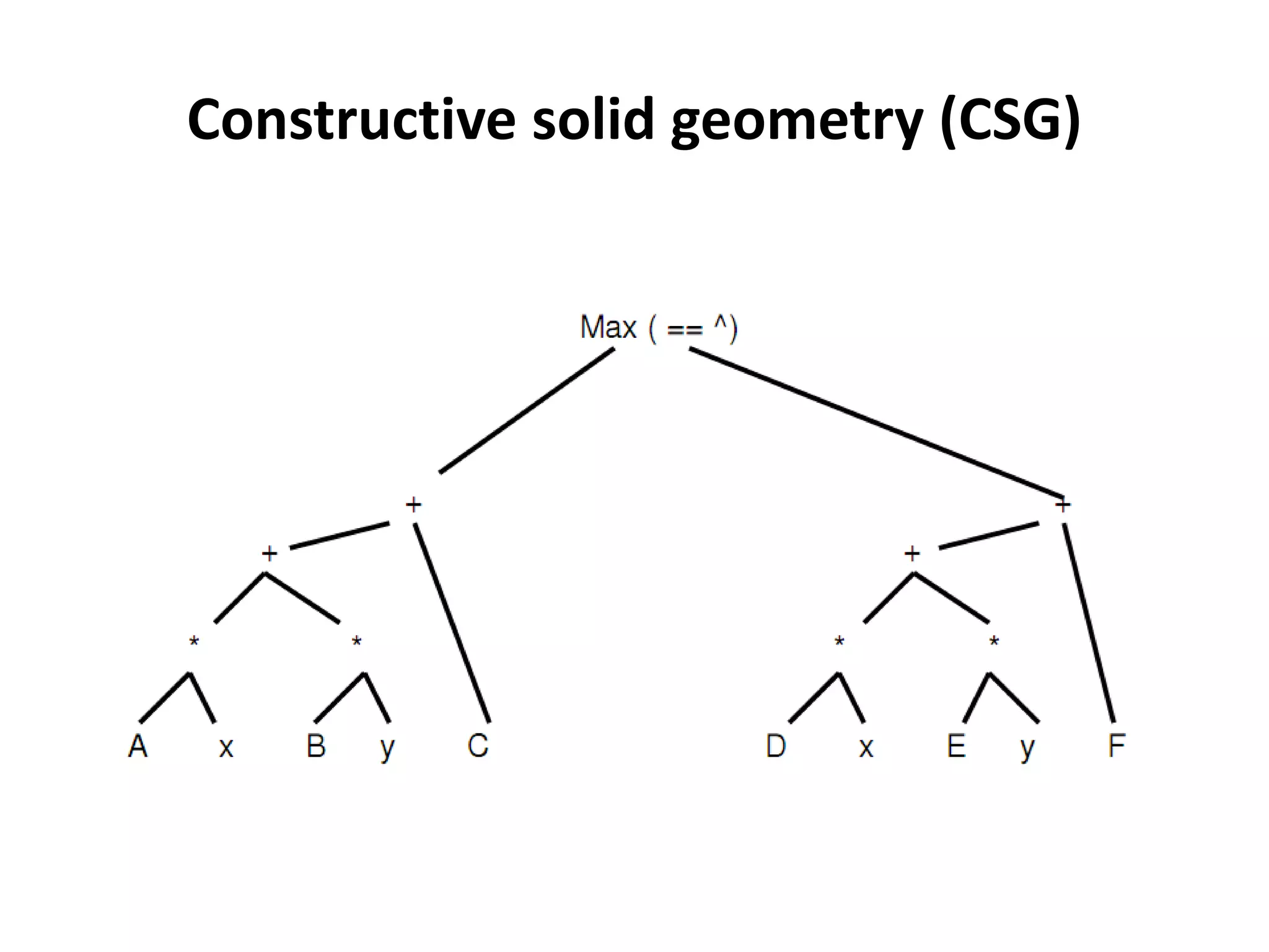
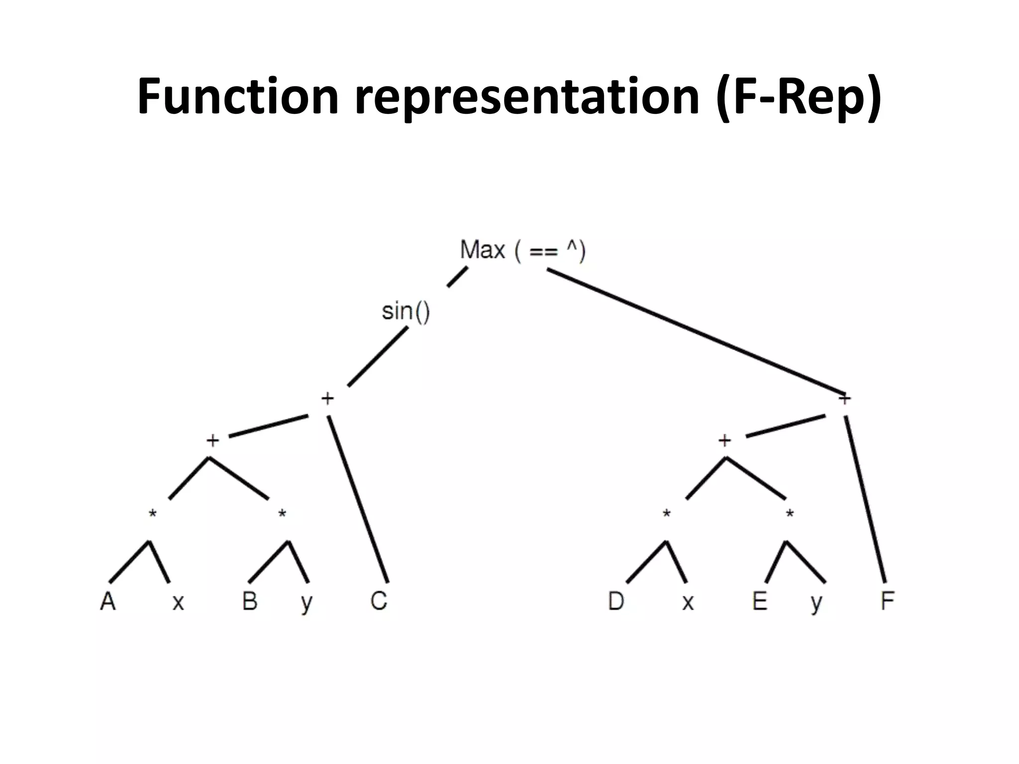
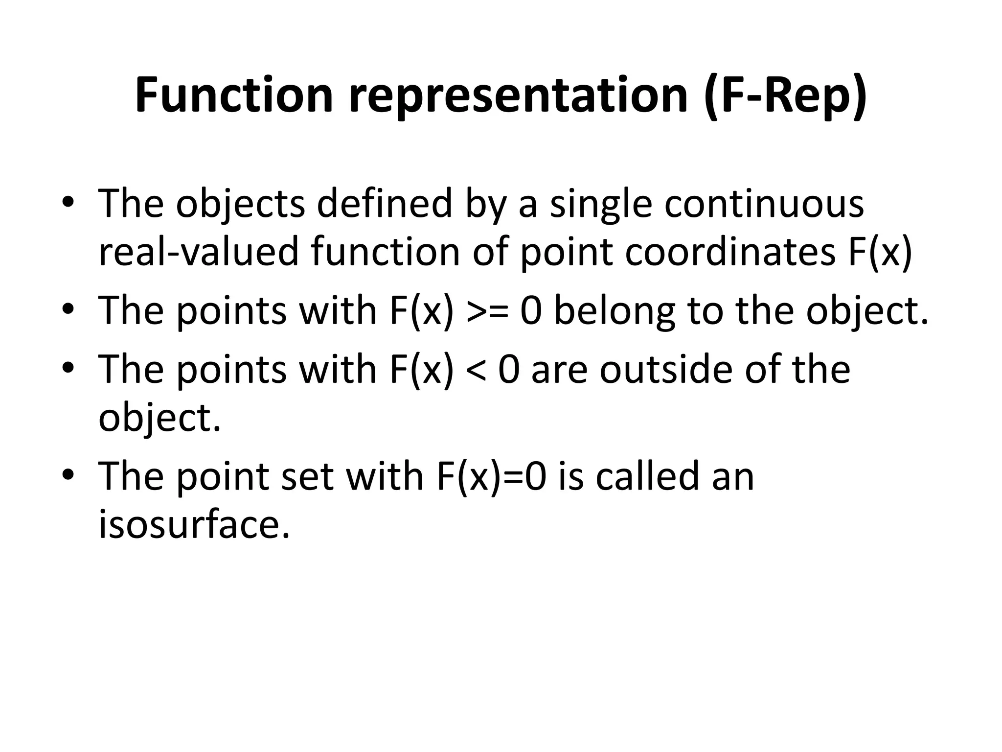
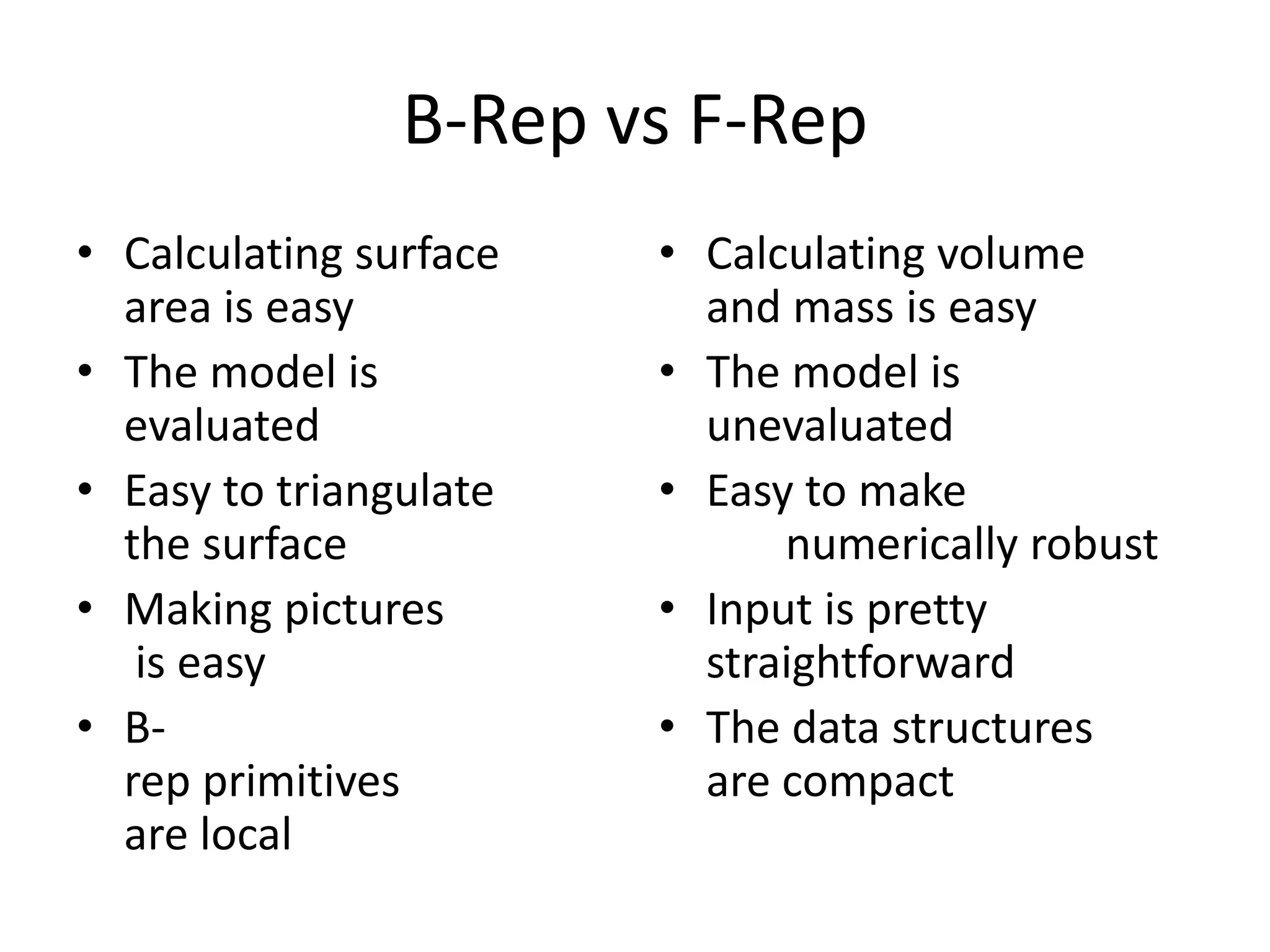
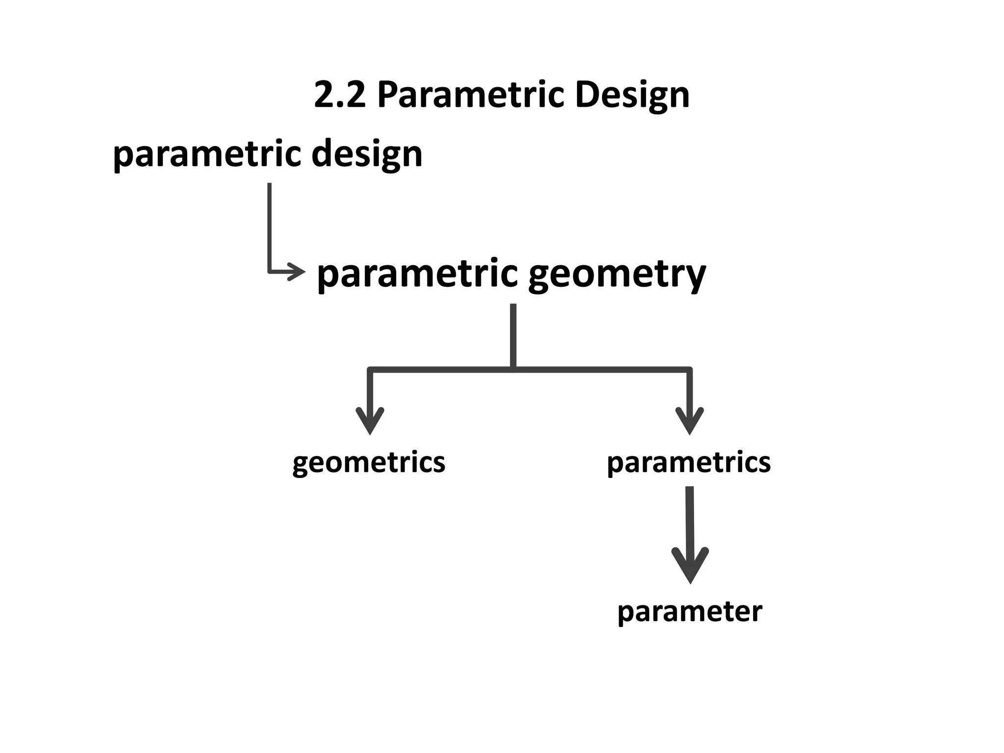
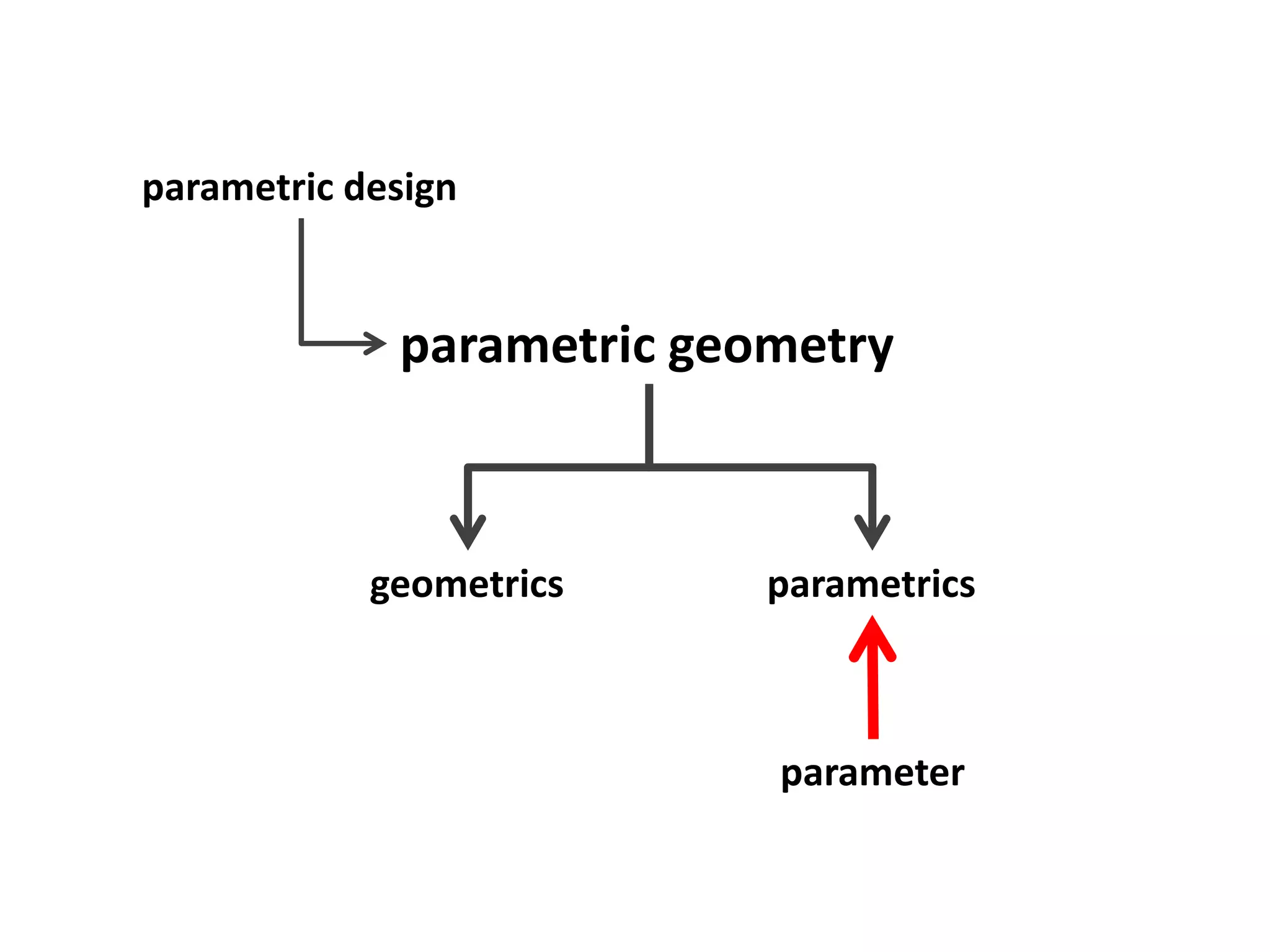
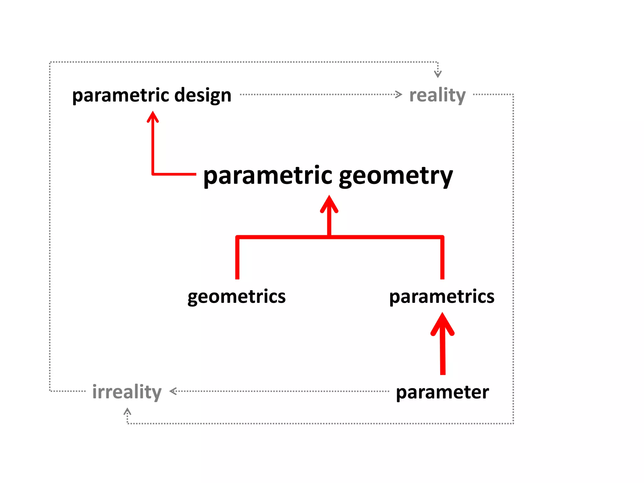
This document provides an overview of CAD (computer-aided design), CAM (computer-aided manufacturing), and CAE (computer-aided engineering). It discusses the history and definitions of these terms. CAD involves using computers to assist in the creation, modification, analysis, or optimization of a design. CAM bridges the gap between conceptual design and manufacturing. CAE uses software to simulate engineering problems like stress analysis. The document then discusses CAD topics like boundary representation, constructive solid geometry, function representation, parametric design, and examples of 2D and 3D CAD software.