Downloaded 297 times
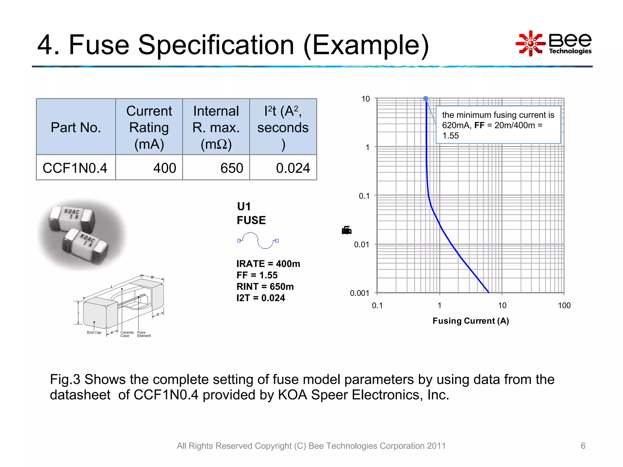
![3. Parameter Settings Irate = the current rating of fuse [A] FF = Fusing Factor, the ratio of the minimum fusing current (the current that fuse start to heat up) to Irate . (e.g. Irate =400mA and the minimum fusing current is 620mA then FF = 620m/400m = 1.55) Rint = internal resistance of fuse I2t = Normal Melting value [A 2 , seconds] From the fuse specification, the model is characterized by setting parameters Irate, FF, Rint and I2t. All Rights Reserved Copyright (C) Bee Technologies Corporation 2011 Model Parameters: Fig.2 Fuse model with default parameters IRATE = 400m FF = 1.55 RINT = 650m I2T = 0.024](https://image.slidesharecdn.com/fusesimplifiedltspice-110802031727-phpapp01/75/Simple-model-of-Fuse-LTspice-5-2048.jpg)
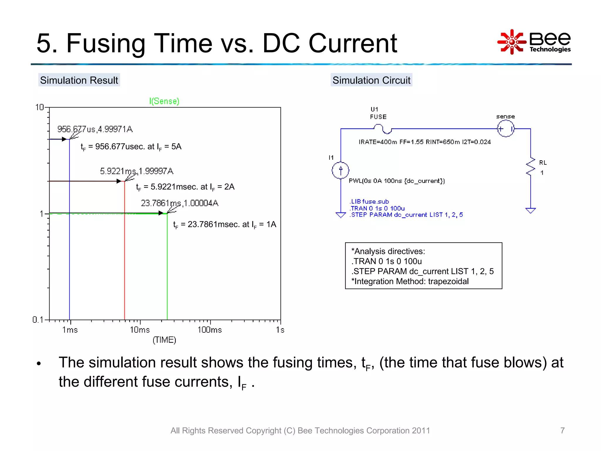
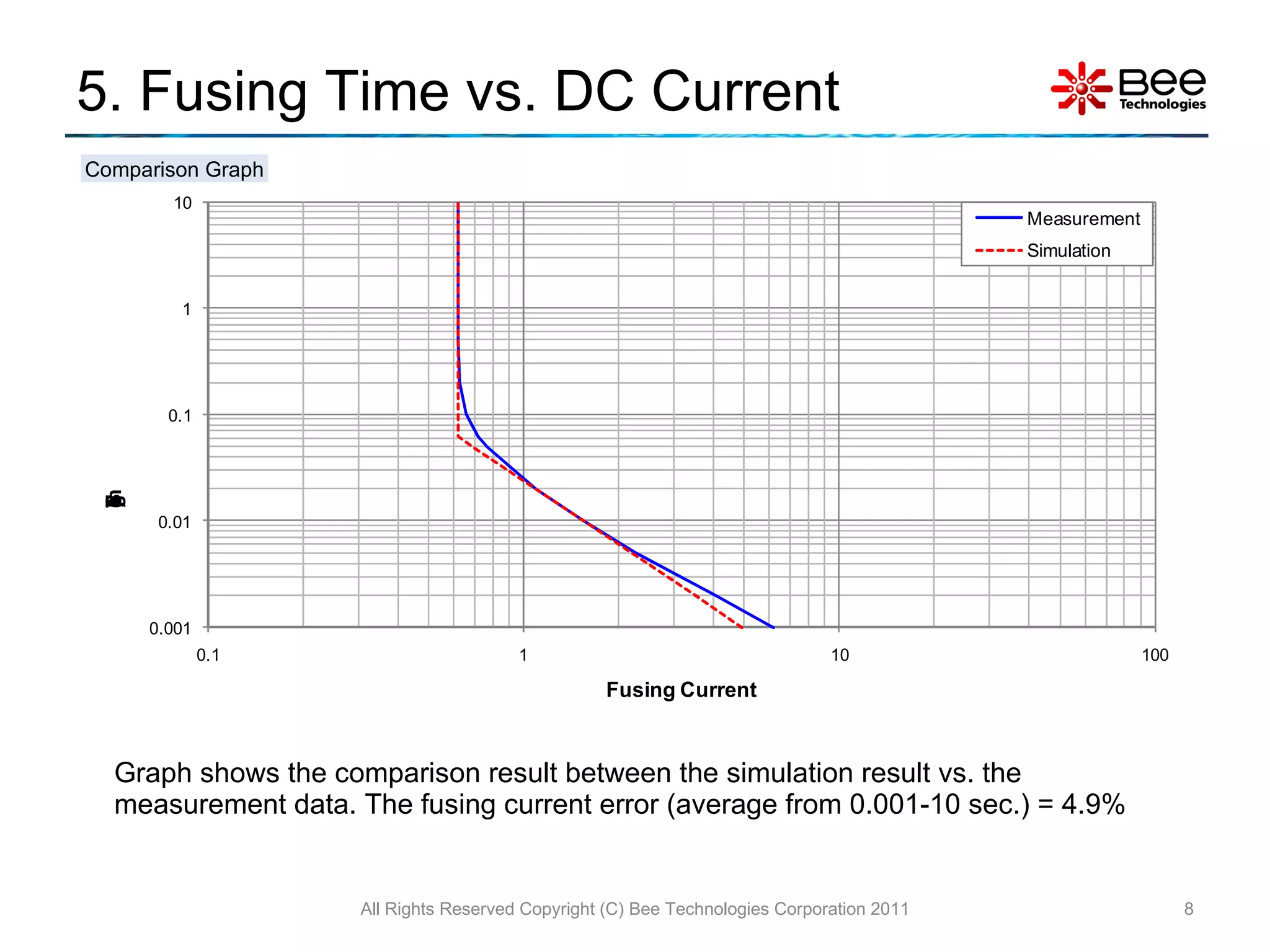
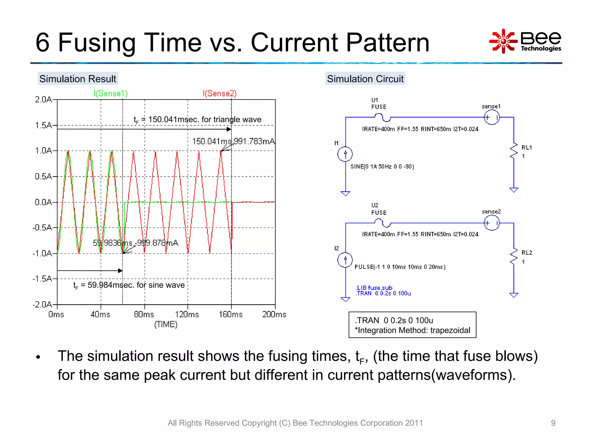
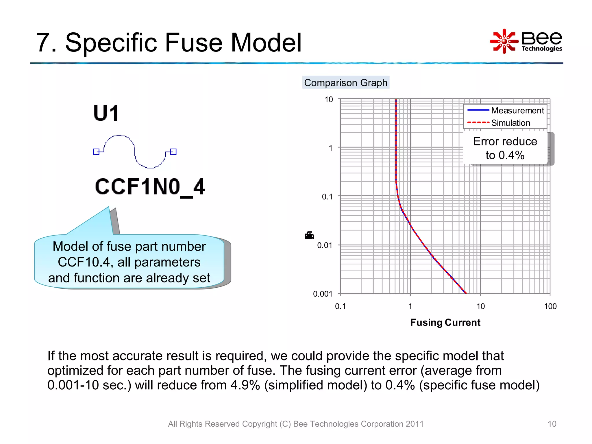
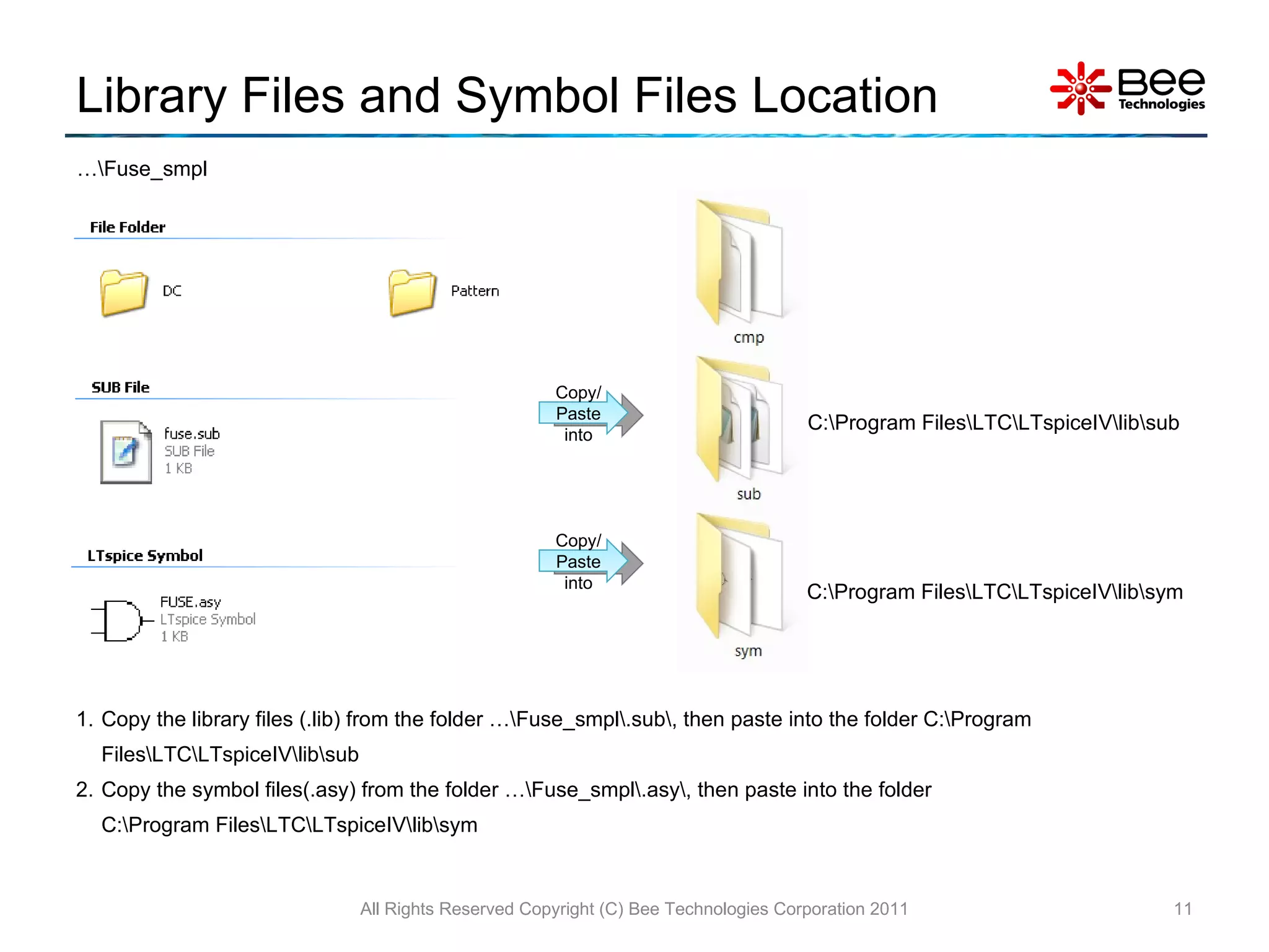
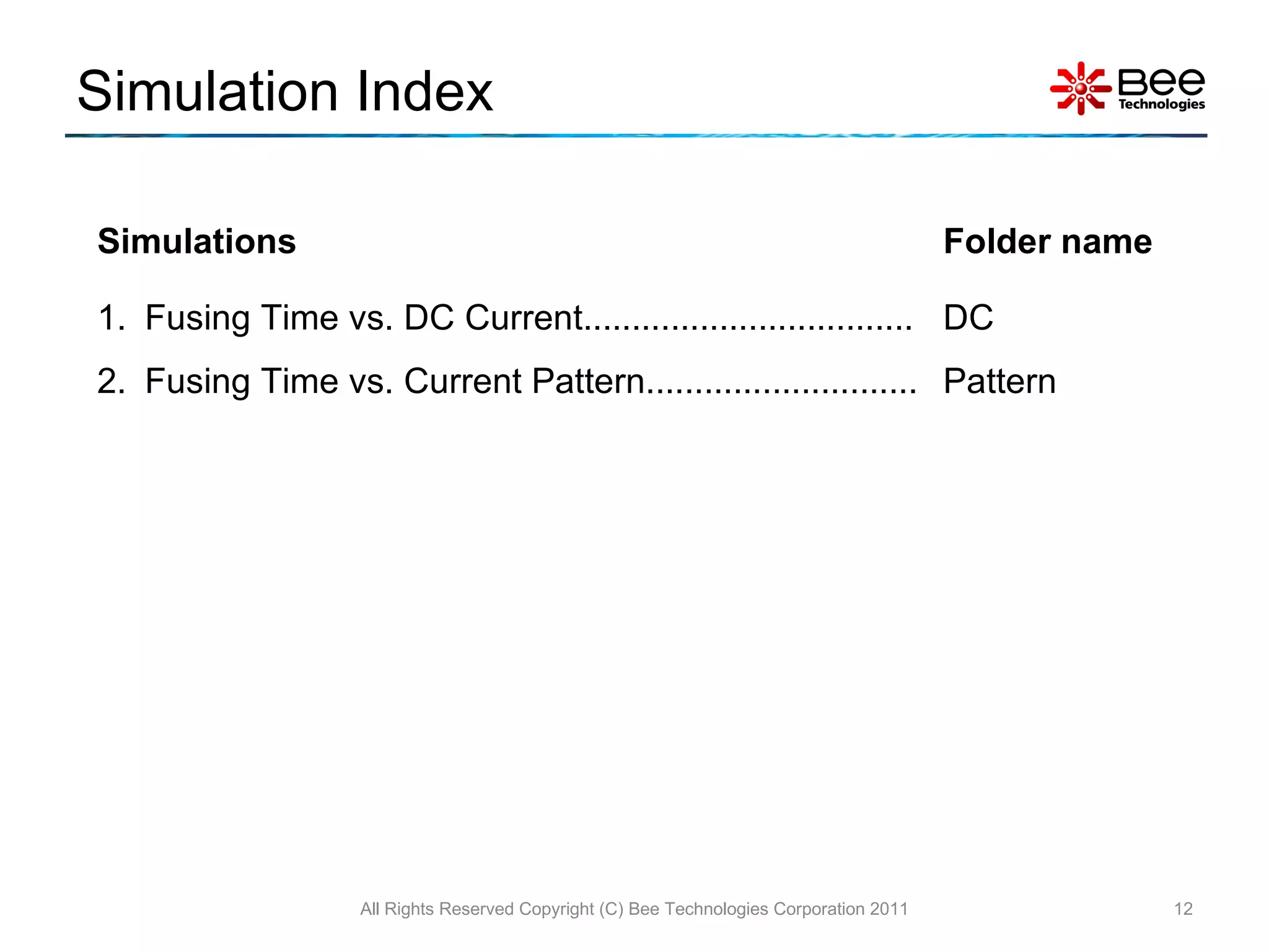

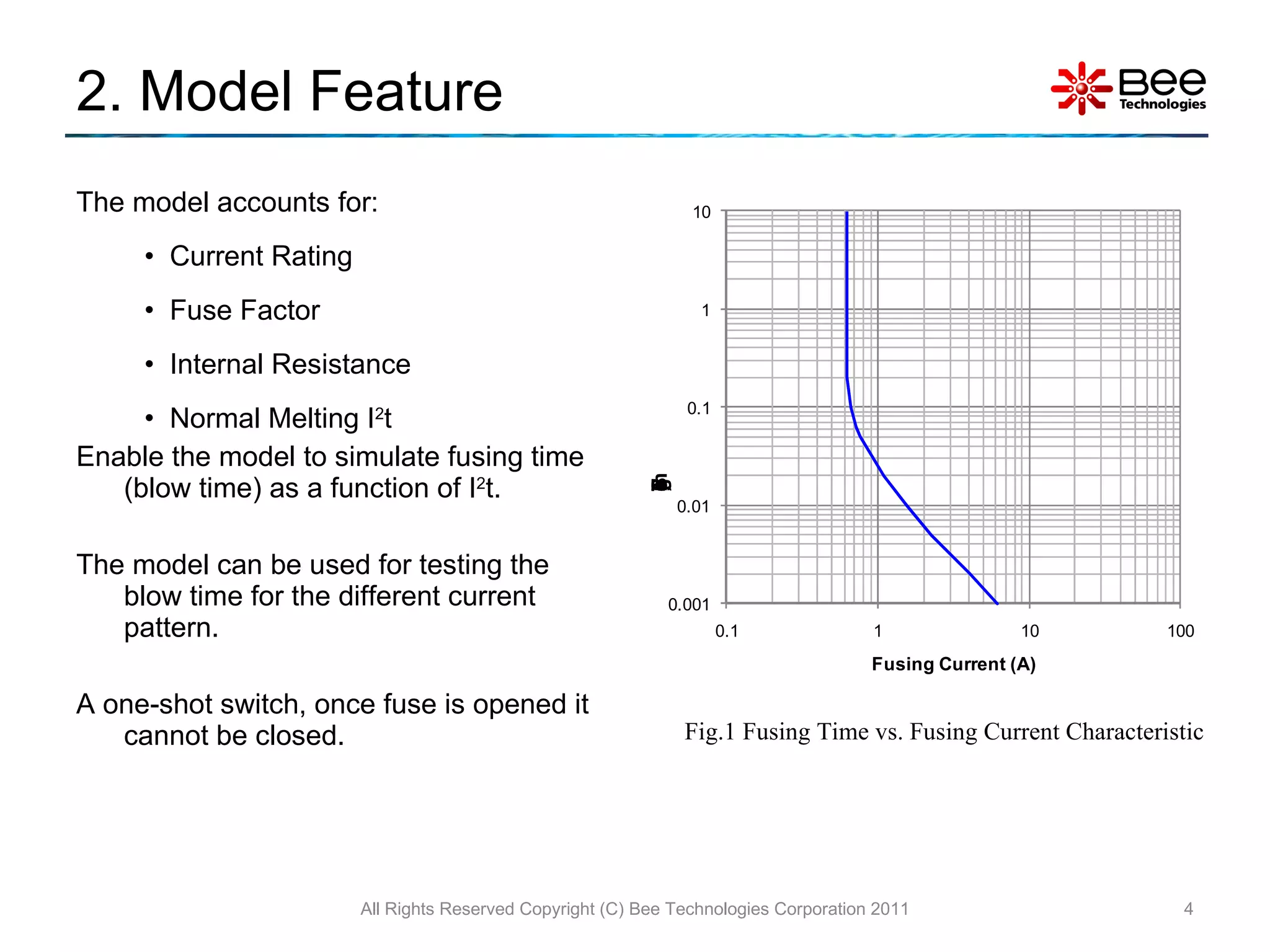
The document describes a simplified SPICE behavioral model for simulating the behavior of fuses in circuits. The model allows users to set parameters like current rating, fuse factor, internal resistance, and normal melting value to simulate how long it takes a fuse to blow under different current conditions. Simulation results are presented demonstrating how fusing time varies based on steady direct current levels and different current waveforms providing the same peak current. Instructions are provided on installing the model libraries and symbols for use in SPICE simulations.


![Vibe Coding vs. Spec-Driven Development [Free Meetup]](https://cdn.slidesharecdn.com/ss_thumbnails/vibecodingvsspecdrivendevelopment-251209105622-43f455e7-thumbnail.jpg?width=640&height=640&fit=bounds)


